
Subscribe to Our Youtube Channel
Related Manuals for Rohde & Schwarz FSVA3000


Summary of Contents for Rohde & Schwarz FSVA3000
- Page 1 ® R&S FSVA3000/ ® R&S FSV3000 Signal and Spectrum Analyzer Getting Started (=NÞ×2) 1330807302...
- Page 2 1330.8073.02 | Version 03 | R&S FSVA3000/R&S FSV3000 ® The following abbreviations are used throughout this manual: R&S FSVA3000 is abbreviated as R&S FSVA3000. R&S ® FSV3000 is abbreviated as R&S FSV3000. R&S ® FSV/A refers to both the R&S FSV3000 and the R&S FSVA3000.
- Page 3 Safety Instructions Instrucciones de seguridad Sicherheitshinweise Consignes de sécurité Risk of injury and instrument damage The instrument must be used in an appropriate manner to prevent electric shock, fire, personal injury or instrument damage. ● Do not open the instrument casing. ●...
- Page 4 Gefahr von Verletzungen und Schäden am Gerät Betreiben Sie das Gerät immer ordnungsgemäß, um elektrischen Schlag, Brand, Verletzungen von Personen oder Geräteschäden zu verhindern. ● Öffnen Sie das Gerätegehäuse nicht. ● Lesen und beachten Sie die "Grundlegenden Sicherheitshinweise", die als gedruckte Broschüre dem Gerät beiliegen. ●...
-
Page 5: Table Of Contents
® ® Contents R&S FSVA3000/R&S FSV3000 Contents 1 Preface..................5 1.1 Key Features..................5 1.2 Conventions Used in the Documentation...........6 2 Safety Information..............8 3 Documentation Overview............9 3.1 Getting Started Manual.................9 3.2 User Manuals and Help................ 9 3.3 Service Manual..................10 3.4 Instrument Security Procedures............10 3.5 Basic Safety Instructions.............. - Page 6 ® ® Contents R&S FSVA3000/R&S FSV3000 6 Trying Out the Instrument...........56 6.1 Measuring a Basic Signal..............56 6.2 Displaying a Spectrogram..............58 6.3 Activating Additional Measurement Channels.........60 6.4 Performing Sequential Measurements..........65 6.5 Setting and Moving a Marker............. 66 6.6 Displaying a Marker Peak List............68 6.7 Zooming into the Display..............
-
Page 7: Preface
For a detailed specification, refer to the data sheet. Due to these features, the R&S FSV3000 and the R&S FSVA3000 are ideal for various measurement tasks, for instance: ● Functional check and repair in service and maintenance due to the excellent usability ●... -
Page 8: Conventions Used In The Documentation
® ® Preface R&S FSVA3000/R&S FSV3000 Conventions Used in the Documentation ● Identifying and analyzing spurious emissions due to the large spurious-free dynamic range and low DANL Conventions Used in the Documentation 1.2.1 Typographical Conventions The following text markers are used throughout this documentation:... - Page 9 ® ® Preface R&S FSVA3000/R&S FSV3000 Conventions Used in the Documentation 1.2.3 Notes on Screenshots When describing the functions of the product, we use sample screenshots. These screenshots are meant to illustrate as many as possible of the provided functions and possible interdependencies between parameters.
-
Page 10: Safety Information
® ® Safety Information R&S FSVA3000/R&S FSV3000 Safety Information The product documentation helps you use the R&S FSV/A safely and efficiently. Follow the instructions provided here and in the printed "Basic Safety Instruc- tions". Keep the product documentation nearby and offer it to other users. -
Page 11: Documentation Overview
® ® Documentation Overview R&S FSVA3000/R&S FSV3000 User Manuals and Help Documentation Overview This section provides an overview of the R&S FSV/A user documentation. Unless specified otherwise, you find the documents on the R&S FSV/A product page at: www.rohde-schwarz.com/product/FSVA3000.html/ www.rohde-schwarz.com/product/FSV3000.html Getting Started Manual Introduces the R&S FSV/A and describes how to set up and start working with the... -
Page 12: Service Manual
® ® Documentation Overview R&S FSVA3000/R&S FSV3000 Data Sheets and Brochures All user manuals are also available for download or for immediate display on the Internet. Service Manual Describes the performance test for checking the rated specifications, module replacement and repair, firmware update, troubleshooting and fault elimination, and contains mechanical drawings and spare part lists. -
Page 13: Release Notes And Open Source Acknowledgment (Osa)
® ® Documentation Overview R&S FSVA3000/R&S FSV3000 Application Notes, Application Cards, White Papers, etc. Release Notes and Open Source Acknowledg- ment (OSA) The release notes list new features, improvements and known issues of the cur- rent firmware version, and describe the firmware installation. -
Page 14: Preparing For Use
® ® Preparing for Use R&S FSVA3000/R&S FSV3000 Putting into Operation Preparing for Use ● Putting into Operation..................12 ● Windows Operating System................20 ● Connecting USB Devices................25 ● Connecting an External Monitor..............27 ● Setting Up a Network (LAN) Connection............28 ●... - Page 15 ® ® Preparing for Use R&S FSVA3000/R&S FSV3000 Putting into Operation Instrument damage caused by electrostatic discharge Electrostatic discharge (ESD) can damage the electronic components of the instrument and the device under test (DUT). Electrostatic discharge is most likely to occur when you connect or disconnect a DUT or test fixture to the instrument's test ports.
- Page 16 ® ® Preparing for Use R&S FSVA3000/R&S FSV3000 Putting into Operation ● Unpacking and Checking the Instrument............14 ● Accessory List....................14 ● Placing or Mounting the Instrument..............15 ● Connecting the AC Power................17 ● Switching the Instrument On and Off..............
- Page 17 ® ® Preparing for Use R&S FSVA3000/R&S FSV3000 Putting into Operation 4.1.3 Placing or Mounting the Instrument The R&S FSV/A is designed for use under laboratory conditions, either on a bench top or in a rack. Bench Top Operation If the R&S FSV/A is operated on a bench top, the surface should be flat. The instrument can be used in horizontal position, standing on its feet, or with the sup- port feet on the bottom extended.
- Page 18 ® ® Preparing for Use R&S FSVA3000/R&S FSV3000 Putting into Operation Risk of injury when stacking instruments A stack of instruments can tilt over and cause injury if not stacked correctly. Furthermore, the instruments at the bottom of the stack can be damaged due to the load imposed by the instruments on top.
- Page 19 ® ® Preparing for Use R&S FSVA3000/R&S FSV3000 Putting into Operation 4.1.4 Connecting the AC Power In the standard version, the R&S FSV/A is equipped with an AC power supply connector. The R&S FSV/A can be used with different AC power voltages and adapts itself automatically to it.
- Page 20 ® ® Preparing for Use R&S FSVA3000/R&S FSV3000 Putting into Operation If the instrument temperature exceeds the limit specified in the data sheet, the R&S FSV/A automatically shuts down to protect the instrument from damage. Risk of losing data If you switch off the running instrument using the rear panel switch or by disconnecting the power cord, the instrument loses its current settings.
- Page 21 ® ® Preparing for Use R&S FSVA3000/R&S FSV3000 Putting into Operation 3. Select the "Start Self-Alignment" button in the "Alignment" dialog box. Once the system correction values have been calculated successfully, a mes- sage is displayed. To display the alignment results again later ●...
-
Page 22: Windows Operating System
® ® Preparing for Use R&S FSVA3000/R&S FSV3000 Windows Operating System Windows Operating System The instrument contains the Windows 10 operating system which has been con- figured according to the instrument's features and needs. Changes in the system setup are only required when peripherals like keyboard or a printer are installed or if the network configuration does not comply with the default settings. - Page 23 ® ® Preparing for Use R&S FSVA3000/R&S FSV3000 Windows Operating System For details and recommendations, see the following Rohde & Schwarz white paper: ● 1EF96: Malware Protection Windows 10 4.2.2 Service Packs and Updates Microsoft regularly creates security updates and other patches to protect Win- dows-based operating systems.
- Page 24 ® ® Preparing for Use R&S FSVA3000/R&S FSV3000 Windows Operating System Secure user mode If the secure user mode option (R&S FSV/A-K33) is installed, an additional account is provided: the "SecureUser". The "SecureUser" is a standard user account with limited functionality. In particular, administrative tasks such as LAN configuration or general instru- ment settings are not available.
- Page 25 ® ® Preparing for Use R&S FSVA3000/R&S FSV3000 Windows Operating System 4.2.3.1 Automatic Login Function When shipped, the instrument automatically logs on the default "Instrument" user to Windows 10 using the default password. Switching users when using the automatic login function Which user account is used is defined during login.
- Page 26 ® ® Preparing for Use R&S FSVA3000/R&S FSV3000 Windows Operating System Adapting the automatic login function to a new password If you change the "Instrument" user's password, which is used during automatic login, this function no longer works. Adapt the settings for the command that acti- vates the auto login function first.
-
Page 27: Connecting Usb Devices
® ® Preparing for Use R&S FSVA3000/R&S FSV3000 Connecting USB Devices All necessary system settings can be defined in the "Start > Settings" menu. (For required settings refer to the Windows 10 documentation and to the hard- ware description). 4.2.5... - Page 28 ® ® Preparing for Use R&S FSVA3000/R&S FSV3000 Connecting USB Devices To disconnect a USB device ► Remove the device from the USB interface of the R&S FSV/A. Windows immediately detects the change in hardware configuration and deac- tivates the corresponding driver.
-
Page 29: Connecting An External Monitor
® ® Preparing for Use R&S FSVA3000/R&S FSV3000 Connecting an External Monitor Connecting an External Monitor You can connect an external monitor (or projector) to the "DVI" or "display port" connector on the rear panel of the R&S FSV/A (see also Chapter 5.2.2, "Display... -
Page 30: Setting Up A Network (Lan) Connection
® ® Preparing for Use R&S FSVA3000/R&S FSV3000 Setting Up a Network (LAN) Connection 5. If necessary, change the screen resolution. Consider the information in the note above. 6. Select the instrument to be used for display: ● "Display 1": internal monitor only ●... - Page 31 ® ® Preparing for Use R&S FSVA3000/R&S FSV3000 Setting Up a Network (LAN) Connection ● To transfer data between a controlling device and the test device, e.g. to run a remote control program. See chapter "Remote Control" in the R&S FSV/A user manual.
- Page 32 ® ® Preparing for Use R&S FSVA3000/R&S FSV3000 Setting Up a Network (LAN) Connection Risk of network failure Consult your network administrator before performing the following tasks: ● Connecting the instrument to the network ● Configuring the network ● Changing IP addresses ●...
- Page 33 ® ® Preparing for Use R&S FSVA3000/R&S FSV3000 Setting Up a Network (LAN) Connection Risk of network errors Connection errors can affect the entire network. If your network does not support DHCP, or if you choose to disable dynamic TCP/IP configuration, you must assign valid address information before connecting the instrument to the LAN.
- Page 34 ® ® Preparing for Use R&S FSVA3000/R&S FSV3000 Setting Up a Network (LAN) Connection If you have entered an invalid IP address or subnet mask, the message "out of range" is displayed in the status line. If the settings are correct, the configura- tion is saved, and you are prompted to restart the instrument.
- Page 35 ® ® Preparing for Use R&S FSVA3000/R&S FSV3000 Setting Up a Network (LAN) Connection 5. Tap the entry named "Internet Protocol Version 4 (TCP/IPv4)" to highlight it. 6. Select the "Properties" button. 7. On the "General" tab, select "Use the following DNS server addresses" and enter your own DNS addresses.
- Page 36 ® ® Preparing for Use R&S FSVA3000/R&S FSV3000 Setting Up a Network (LAN) Connection Each instrument is delivered with an assigned computer name, but this name can be changed. The default instrument name is a non-case-sensitive string with the following syn- tax: <Type><variant>-<serial_number>...
-
Page 37: Configuring The Initial Instrument Settings
® ® Preparing for Use R&S FSVA3000/R&S FSV3000 Protecting Data Using the Secure User Mode Configuring the Initial Instrument Settings This section describes how to set up the R&S FSV/A initially. For further basic instrument settings, see the R&S FSV/A User Manual. - Page 38 ® ® Preparing for Use R&S FSVA3000/R&S FSV3000 Protecting Data Using the Secure User Mode mode the instrument’s solid-state drive is write-protected so that no information can be written to memory permanently. Data that the R&S FSV/A normally stores on the solid-state drive is redirected to volatile memory instead, which remains available only until the instrument is switched off.
- Page 39 ® ® Preparing for Use R&S FSVA3000/R&S FSV3000 Protecting Data Using the Secure User Mode Restricted operation Since permanent storage is not possible, the following functions are not available in secure user mode: ● Firmware update ● Activating a new option key Furthermore, since the "SecureUser"...
- Page 40 ® ® Preparing for Use R&S FSVA3000/R&S FSV3000 Protecting Data Using the Secure User Mode The secure user mode setting and automatic login is automatically deactivated when the "Instrument" user logs on. The "SecureUser" is no longer available. For administrators ("Instrument" user), the secure user mode setting is available in the general system configuration settings ([Setup] key >...
-
Page 41: Instrument Tour
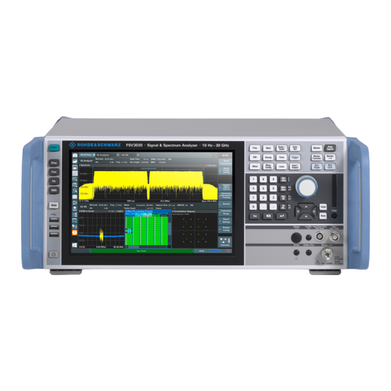
® ® Instrument Tour R&S FSVA3000/R&S FSV3000 Front Panel View Instrument Tour Front Panel View This chapter describes the front panel, including all function keys and connectors. Figure 5-1: Front panel view of R&S FSV/A 1 = POWER key 2 = USB connectors... - Page 42 ® ® Instrument Tour R&S FSVA3000/R&S FSV3000 Front Panel View Instrument damage caused by cleaning agents Cleaning agents contain substances such as solvents (thinners, acetone, etc.), acids, bases, or other substances. Solvents can damage the front panel labeling, plastic parts, or screens, for example.
- Page 43 ® ® Instrument Tour R&S FSVA3000/R&S FSV3000 Front Panel View Table 5-1: System keys System key Assigned functions [Preset] Resets the instrument to the default state. [Setup] Provides basic instrument configuration functions, e.g.: ● Reference frequency (external/internal), noise source ●...
- Page 44 ® ® Instrument Tour R&S FSVA3000/R&S FSV3000 Front Panel View Risk of touchscreen damage Inappropriate tools or excessive force can damage the touchscreen. Observe the following instructions when operating the touchscreen: ● Never touch the screen with ball point pens or other sharp objects, use your fingers instead.
- Page 45 ® ® Instrument Tour R&S FSVA3000/R&S FSV3000 Front Panel View 1 = Toolbar with standard application functions, e.g. print, save/open file etc. 2 = Tabs for individual measurement channels 3 = Channel bar for firmware and measurement settings 4 = Input field for measurement setting...
- Page 46 ® ® Instrument Tour R&S FSVA3000/R&S FSV3000 Front Panel View Table 5-2: Function keys Function key Assigned functions Basic measurement settings [Freq.] Sets the center frequency and the start and stop frequencies for the frequency range under consideration. This key is also used to set the frequency offset and the signal track function.
- Page 47 ® ® Instrument Tour R&S FSVA3000/R&S FSV3000 Front Panel View Function key Assigned functions [Marker ->] Used for search functions of the measurement markers (maxi- mum/minimum of the trace). Assigns the marker frequency to the center frequency, and the marker level to the reference level.
- Page 48 ® ® Instrument Tour R&S FSVA3000/R&S FSV3000 Front Panel View Table 5-3: Keys on the keypad Type of key Description Alphanumeric keys Enter numbers and (special) characters in edit dialog boxes. Decimal point Inserts a decimal point "." at the cursor position.
- Page 49 ® ® Instrument Tour R&S FSVA3000/R&S FSV3000 Front Panel View 5.1.8.1 Rotary Knob The rotary knob has several functions: ● For numeric entries: increments (clockwise direction) or decrements (counter- clockwise direction) the instrument parameter at a defined step width ● In lists: toggles between entries ●...
- Page 50 ® ® Instrument Tour R&S FSVA3000/R&S FSV3000 Front Panel View ● In windows or dialog boxes with horizontal scroll bar, move the scroll bar. 5.1.9 Undo/Redo Keys ● The [Undo] key reverts the previous action, i.e. the status before the previous action is retrieved.
- Page 51 ® ® Instrument Tour R&S FSVA3000/R&S FSV3000 Front Panel View Connect headphones equipped with a miniature jack plug to the AF Out female connector. Set the output voltage using the "Volume" control above the female connector. Risk of hearing damage Before putting on the headphones, make sure that the volume setting is not too high to protect your hearing.
-
Page 52: Rear Panel View
® ® Instrument Tour R&S FSVA3000/R&S FSV3000 Rear Panel View Risk of instrument damage Do not overload the input. For maximum allowed values, see the data sheet. A DC input voltage (for AC coupling) of 50 V must never be excee- ded. - Page 53 ® ® Instrument Tour R&S FSVA3000/R&S FSV3000 Rear Panel View 15 = IEEE 488/ IEC625/ SCPI (GPIB) interface (requires option R&S FSV3-B5) 16 = REF In/Out connectors 17 = Trigger 2 (In/Out) connector 18 = Noise Source Control (requires option R&S FSV3-B28V) 5.2.1...
- Page 54 ® ® Instrument Tour R&S FSVA3000/R&S FSV3000 Rear Panel View For details, see Chapter 4.5, "Setting Up a Network (LAN) Connection", on page 28. 5.2.4 The rear panel provides four additional female USB (USB-A) connectors to con- nect devices like a keyboard, a mouse or a memory stick (see also Chapter 5.1.2,...
- Page 55 ® ® Instrument Tour R&S FSVA3000/R&S FSV3000 Rear Panel View Short-circuit hazard Always observe the designated pin assignment. A short-circuit can damage the port. 5.2.7 Trigger 2/3 In/Out The additional female BNC Trigger 2 In/Out connector and the optional Trigger 3 (output) connector allow the R&S FSV/A to receive additional external signals or...
- Page 56 ® ® Instrument Tour R&S FSVA3000/R&S FSV3000 Rear Panel View 5.2.11 REF Input / REF Output The REF Input connectors are used to provide an external reference signal to the R&S FSV/A. The REF Output connectors can be used to provide an external reference signal (or the optional OCXO reference signal) from the R&S FSV/A to other devices...
- Page 57 ® ® Instrument Tour R&S FSVA3000/R&S FSV3000 Rear Panel View Warm-up time for OCXO When the instrument is switched on, the OCXO requires an extended warm-up time (see data sheet). 5.2.14 External Generator Control Option (R&S FSV3-B10) The external generator control option uses a LAN connection and the "AUX con- trol"...
-
Page 58: Trying Out The Instrument
® ® Trying Out the Instrument R&S FSVA3000/R&S FSV3000 Measuring a Basic Signal Trying Out the Instrument This chapter introduces the most important functions and settings of the R&S FSV/A step by step. The complete description of the functionality and its usage is given in the R&S FSV/A User Manual. - Page 59 ® ® Trying Out the Instrument R&S FSVA3000/R&S FSV3000 Measuring a Basic Signal 5. Tap the "Calibration Frequency RF" option. Leave the frequency at the default 64 MHz, with a narrowband spectrum. The calibration signal is now sent to the RF input of the R&S FSV/A. By...
-
Page 60: Displaying A Spectrogram
® ® Trying Out the Instrument R&S FSVA3000/R&S FSV3000 Displaying a Spectrogram b) Tap the "Frequency" button. c) In the "Center" field, enter 64 on the number pad on the front panel. d) Press the "MHz" key next to the number pad. - Page 61 ® ® Trying Out the Instrument R&S FSVA3000/R&S FSV3000 Displaying a Spectrogram shows the frequency, the y-axis shows the time. A third dimension, the power level, is indicated by different colors. Thus you can see how the strength of the signal varies over time for different frequencies.
-
Page 62: Activating Additional Measurement Channels
® ® Trying Out the Instrument R&S FSVA3000/R&S FSV3000 Activating Additional Measurement Channels You see the spectrogram compared to the standard spectrum display. Since the calibration signal does not change over time, the color of the frequency levels does not change over time, i.e. vertically. The legend at the top of the spectrogram window describes the power levels the colors represent. - Page 63 ® ® Trying Out the Instrument R&S FSVA3000/R&S FSV3000 Activating Additional Measurement Channels 2. On the "New Channel" tab of the "Signal + Spectrum Mode" dialog box, tap the "Spectrum" button. Figure 6-5: Adding a new measurement channel 3. Change the frequency range for this spectrum display: In the "Frequency"...
- Page 64 ® ® Trying Out the Instrument R&S FSVA3000/R&S FSV3000 Activating Additional Measurement Channels Figure 6-6: Frequency spectrum of the calibration signal with a larger span 4. Repeat the previous steps to activate a third Spectrum window. Change the frequency range for this spectrum display: In the "Frequency"...
- Page 65 ® ® Trying Out the Instrument R&S FSVA3000/R&S FSV3000 Activating Additional Measurement Channels Figure 6-7: Time domain display of the calibration signal 5. Create a new channel for I/Q analysis: a) Press the [Mode] key. b) Tap the "IQ Analyzer" button to activate a channel for the I/Q Analyzer application.
- Page 66 ® ® Trying Out the Instrument R&S FSVA3000/R&S FSV3000 Activating Additional Measurement Channels d) Drag the "Real/Imag (I/Q)" icon from the evaluation bar to the SmartGrid. Figure 6-8: Inserting a Real/Imag diagram for I/Q analysis e) Close the SmartGrid mode.
-
Page 67: Performing Sequential Measurements
® ® Trying Out the Instrument R&S FSVA3000/R&S FSV3000 Performing Sequential Measurements Figure 6-9: The "MultiView" tab Performing Sequential Measurements Although only one measurement can be performed at any one time, the measure- ments configured in the active channels can be performed sequentially, that means: one after the other, automatically, either once or continuously. -
Page 68: Setting And Moving A Marker
® ® Trying Out the Instrument R&S FSVA3000/R&S FSV3000 Setting and Moving a Marker Figure 6-10: "MultiView" tab with active Sequencer Figure 6-10, the "Spectrum 2" measurement is currently active (indicated by the "channel active" icon in the tab label). - Page 69 ® ® Trying Out the Instrument R&S FSVA3000/R&S FSV3000 Setting and Moving a Marker Press the "Split/Maximize" key on the front panel to maximize the spectrum window, as we currently do not need the spectrogram display. 4. Press the "RUN SINGLE" key on the front panel to perform a single sweep so we have a fixed trace to set a marker on.
-
Page 70: Displaying A Marker Peak List
® ® Trying Out the Instrument R&S FSVA3000/R&S FSV3000 Displaying a Marker Peak List Displaying a Marker Peak List The marker peak list determines the frequencies and levels of peaks in the spec- trum automatically. We will display a marker peak list for the Spectrum 2 channel. -
Page 71: Zooming Into The Display
® ® Trying Out the Instrument R&S FSVA3000/R&S FSV3000 Zooming into the Display b) Tap the "Marker Config" softkey in the "Marker" menu. c) Tap the "Search" tab in the "Marker" dialog box. d) In the "Threshold" field, enter -68 dBm. - Page 72 ® ® Trying Out the Instrument R&S FSVA3000/R&S FSV3000 Zooming into the Display 2. Tap the diagram near the first peak and drag your finger to the opposite corner of the zoom area. A white rectangle is displayed from the point where you tap- ped to the current position.
- Page 73 ® ® Trying Out the Instrument R&S FSVA3000/R&S FSV3000 Zooming into the Display Figure 6-14: Zoomed peak with increased number of sweep points Note that the trace becomes much more precise. Tap the "Multiple Zoom" icon in the toolbar again and define a zoom area around markers M4, M5 and M6.
- Page 74 ® ® Trying Out the Instrument R&S FSVA3000/R&S FSV3000 Zooming into the Display Figure 6-15: Multiple zoom windows 5. Tap the "Multiple Zoom" icon in the toolbar again and define a zoom area around marker M8. 6. To increase the size of the third zoom window, drag the "splitter" between the windows to the left or right or up or down.
-
Page 75: Zooming Into The Display Permanently
® ® Trying Out the Instrument R&S FSVA3000/R&S FSV3000 Zooming into the Display Permanently Figure 6-16: Enlarged zoom window Zooming into the Display Permanently The zoomed results from Chapter 6.7, "Zooming into the Display", on page 69 were only graphical changes to the display. Now we would like to change the measurement settings such that the zoomed result is maintained permanently. - Page 76 ® ® Trying Out the Instrument R&S FSVA3000/R&S FSV3000 Zooming into the Display Permanently 3. Select the (graphical) zoom icon on the toolbar. Any subsequent touch gestures define the zoom area for the zoom display. 4. Place two fingers on the diagram, to the left and right of the marker, and stretch them apart.
- Page 77 ® ® Trying Out the Instrument R&S FSVA3000/R&S FSV3000 Zooming into the Display Permanently The displayed span and the number of displayed sweep points is smaller than before, all other measurement settings remain unchanged. 6. Tap the "Measurement Zoom" icon on the toolbar for a second or so.
-
Page 78: Saving Settings
® ® Trying Out the Instrument R&S FSVA3000/R&S FSV3000 Saving Settings Saving Settings To restore the results of our measurements later, we will store the instrument set- tings to a file. To save the instrument settings to a file Tap the "Save" icon in the toolbar. - Page 79 ® ® Trying Out the Instrument R&S FSVA3000/R&S FSV3000 Saving Settings Figure 6-17: Saving the instrument settings to a file 4. Tap the "Save" button. The file MyMultiViewSetup.dfl is stored in the default directory C:/R_S/ instr/user. To load stored instrument settings You can restore the settings to the instrument at any time using the settings file.
-
Page 80: Printing And Saving Results
® ® Trying Out the Instrument R&S FSVA3000/R&S FSV3000 Printing and Saving Results 3. In the "Load" dialog box, select the MyMultiViewSetup.dfl file in the default directory C:/R_S/instr/user. 4. Tap the "Load" button. All instrument settings are restored and the display should resemble... - Page 81 ® ® Trying Out the Instrument R&S FSVA3000/R&S FSV3000 Printing and Saving Results Figure 6-18: Screenshot of the current display Getting Started 1330.8073.02 ─ 03...
-
Page 82: Operating The Instrument
® ® Operating the Instrument R&S FSVA3000/R&S FSV3000 Operating the Instrument This chapter provides an overview on how to work with the R&S FSV/A. It describes: ● What kind of information is displayed in the diagram area ● How to operate the R&S FSV/A via the front panel keys and other interaction methods ●... -
Page 83: Understanding The Display Information
® ® Operating the Instrument R&S FSVA3000/R&S FSV3000 Understanding the Display Information Understanding the Display Information The following figure shows a measurement diagram in Spectrum mode. All differ- ent information areas are labeled. They are explained in more detail in the follow- ing sections. -
Page 84: Channel Bar
® ® Operating the Instrument R&S FSVA3000/R&S FSV3000 Understanding the Display Information ● Channel Bar....................82 ● Window Title Bar..................... 86 ● Marker Information..................87 ● Frequency and Span Information in Diagram Footer........88 ● Instrument and Status Information..............88 ●... - Page 85 ® ® Operating the Instrument R&S FSVA3000/R&S FSV3000 Understanding the Display Information Icons in the channel bar yellow star icon on the tab label (sometimes referred to as a "dirty flag") indicates that invalid or inconsistent data is displayed, that is: the trace no longer matches the displayed instrument settings.
- Page 86 ® ® Operating the Instrument R&S FSVA3000/R&S FSV3000 Understanding the Display Information Resolution bandwidth that has been set. If the bandwidth does not correspond to the value for automatic coupling, a green bullet appears in front of the field. Video bandwidth that has been set.
- Page 87 ® ® Operating the Instrument R&S FSVA3000/R&S FSV3000 Understanding the Display Information Table 7-2: Common settings displayed in the channel bar "SGL" The sweep is set to single sweep mode. "Sweep The current signal count for measurement tasks that involve a specific number Count"...
-
Page 88: Window Title Bar
® ® Operating the Instrument R&S FSVA3000/R&S FSV3000 Understanding the Display Information Changing the Channel Name The measurement channels are labeled with their default name. If that name already exists, a sequential number is added. You can change the name of the measurement channel by double-tapping the name in the channel bar and enter- ing a new name. -
Page 89: Marker Information
® ® Operating the Instrument R&S FSVA3000/R&S FSV3000 Understanding the Display Information AVERAGE detector RMS detector QUASIPEAK detector (4) Trace Mode Sweep mode: Clrw CLEAR/WRITE MAX HOLD MIN HOLD AVERAGE (Lin/Log/Pwr) View VIEW (5) Smoothing factor Smth Smoothing factor, if enabled. -
Page 90: Frequency And Span Information In Diagram Footer
® ® Operating the Instrument R&S FSVA3000/R&S FSV3000 Understanding the Display Information X-value X-value of the marker Y-value Y-value of the marker Func Activated marker or measurement function Func .Result Result of the active marker or measurement function The functions are indicated with the following abbreviations:... -
Page 91: Error Information
® ® Operating the Instrument R&S FSVA3000/R&S FSV3000 Understanding the Display Information In the MultiView tab, the status bar always displays the information for the cur- rently selected measurement. The following information is displayed: Instrument status The instrument is configured for operation with an external reference. -
Page 92: Accessing The Functionality
® ® Operating the Instrument R&S FSVA3000/R&S FSV3000 Accessing the Functionality Table 7-3: Status bar information - color coding Color Type Description Error An error occurred at the start or during a measurement, e.g. due to missing data or wrong settings, so that the measurement cannot be started or completed correctly. - Page 93 ® ® Operating the Instrument R&S FSVA3000/R&S FSV3000 Accessing the Functionality ● Icons on the tool bar in the touchscreen ● Displayed setting on the touchscreen 7.2.1 Toolbar Standard functions can be performed via the icons in the toolbar at theleft side of the screen.
- Page 94 ® ® Operating the Instrument R&S FSVA3000/R&S FSV3000 Accessing the Functionality Icon Description Measurement zoom: applies to the next display you select; Displays a dotted rectangle in the diagram that can be expanded to define the zoom area; the selected diagram is replaced by a new diagram with adapted measurement settings which displays the selected extract of the trace.
- Page 95 Event based actions manager: opens a dialog to configure actions based on specific events For details see General Instrument Setup in the R&S FSV3000/ FSVA3000 base unit user manual. Application starter: opens a dialog to start an external application directly from the R&S FSV/A firmware.
- Page 96 ® ® Operating the Instrument R&S FSVA3000/R&S FSV3000 Accessing the Functionality The "More" softkey indicates that the menu contains more softkeys than can be displayed at once on the screen. When pressed, it displays the next set of soft- keys.
- Page 97 ® ® Operating the Instrument R&S FSVA3000/R&S FSV3000 Accessing the Functionality Figure 7-1: Context menu for a result display with SCPI Recorder functions If SCPI Recorder functions are not available, for example for channel bar settings or in some applications, the context menu contains functions for the selected item.
-
Page 98: Entering Data
® ® Operating the Instrument R&S FSVA3000/R&S FSV3000 Entering Data The on-screen keyboard display can be switched on and off as desired using the "On-Screen Keyboard" function key beneath the screen. When you press this key, the display switches between the following options: ●... - Page 99 ® ® Operating the Instrument R&S FSVA3000/R&S FSV3000 Entering Data Transparent dialog boxes You can change the transparency of the dialog boxes to see the results in the windows behind the dialog box. Thus, you can see the effects that the changes you make to the settings have on the results immediately.
- Page 100 ® ® Operating the Instrument R&S FSVA3000/R&S FSV3000 Entering Data 1. In the input field for a numeric value, select the pencil icon to switch to exten- ded data entry mode. 2. Use the left and right arrow keys to scroll through the individual digits of the indicated value.
- Page 101 For details, see "System Configuration Setttings" in the R&S FSV3000/ FSVA3000 base unit user manual. To enter numbers and (special) characters via the keypad 1. Press the key once to enter the first possible value.
-
Page 102: Touchscreen Gestures
® ® Operating the Instrument R&S FSVA3000/R&S FSV3000 Touchscreen Gestures To abort the entry ► Press the [ESC] key. The dialog box is closed without changing the settings. Table 7-5: Keys for alphanumeric parameters Key name Series of (special) characters and number provided (upper inscription) 7 µ... - Page 103 ® ® Operating the Instrument R&S FSVA3000/R&S FSV3000 Touchscreen Gestures Figure 7-3: Tapping Double-tapping Tap the screen twice, in quick succession. Double-tap a diagram or the window title bar to maximize a window in the display, or to restore the original size.
- Page 104 ® ® Operating the Instrument R&S FSVA3000/R&S FSV3000 Touchscreen Gestures You can pinch or spread your fingers vertically, horizontally, or diagonally. The direction in which you move your fingers determines which dimension of the dis- play is changed. Figure 7-5: Pinching Figure 7-6: Spreading Getting Started 1330.8073.02 ─...
- Page 105 ® ® Operating the Instrument R&S FSVA3000/R&S FSV3000 Touchscreen Gestures Touch gestures in diagrams change measurement settings When you change the display using touch gestures, the corresponding measurement settings are adapted. This is different to selecting an area on the screen in zoom mode, where merely the resolution of the displayed trace points is changed temporarily (graphical zoom).
-
Page 106: Displaying Results
® ® Operating the Instrument R&S FSVA3000/R&S FSV3000 Displaying Results Mouse vs. touch actions Any user interface elements that react to actions by a mouse pointer also react to finger gestures on the screen, and vice versa. The following touch actions corre-... - Page 107 ® ® Operating the Instrument R&S FSVA3000/R&S FSV3000 Displaying Results The R&S FSV/A allows you to configure the display to suit your specific require- ments and optimize analysis. 7.5.1 Activating and Deactivating Channels When you activate an application, a new measurement channel is created which determines the measurement settings for that application.
- Page 108 ® ® Operating the Instrument R&S FSVA3000/R&S FSV3000 Displaying Results 2. In the "Mode" dialog box, select the required application on the "New Chan- nel" tab. A new tab is displayed for the new channel. To change the application in an active channel 1.
- Page 109 ® ® Operating the Instrument R&S FSVA3000/R&S FSV3000 Displaying Results ● All evaluation methods available for the currently selected measurement are displayed as icons in the evaluation bar. If the evaluation bar contains more icons than can be displayed at once on the screen, it can be scrolled vertically.
- Page 110 ® ® Operating the Instrument R&S FSVA3000/R&S FSV3000 Displaying Results Figure 7-7: Moving a window in SmartGrid mode The brown area indicates the possible "drop area" for the window, i.e. the area in which the window can be placed. A blue area indicates the (approximate) layout of the window as it would be if the icon were dropped at the current position.
- Page 111 ® ® Operating the Instrument R&S FSVA3000/R&S FSV3000 Displaying Results Figure 7-8: SmartGrid window positions 1 = Insert row above or below the existing row 2 = Create a new column in the existing row 3 = Replace a window in the existing row...
- Page 112 ® ® Operating the Instrument R&S FSVA3000/R&S FSV3000 Displaying Results To close the SmartGrid mode and restore the previous softkey menu select the "Close" icon in the right-hand corner of the toolbar, or press any key. 7.5.2.3 How to Add a New Result Window Each type of evaluation is displayed in a separate window.
- Page 113 ® ® Operating the Instrument R&S FSVA3000/R&S FSV3000 Displaying Results 2. Drag the evaluation over the SmartGrid. A blue area shows where the window will be placed. 3. Move the window until a suitable area is indicated in blue. 4. Drop the window in the target area.
- Page 114 ® ® Operating the Instrument R&S FSVA3000/R&S FSV3000 Displaying Results ► To change the size of two neighboring windows, drag the splitter between the windows in either direction. 7.5.4 Switching Between a Split and Maximized Window Dis- play To get an overview of the results, displaying several windows at the same time may be helpful.
-
Page 115: Getting Help
® ® Operating the Instrument R&S FSVA3000/R&S FSV3000 Getting Help Getting Help If any questions or problems concerning the R&S FSV/A arise, an extensive online help system is provided on the instrument and can be consulted at any time. The help system is context-sensitive and provides information specifically for the current operation or setting to be performed. -
Page 116: Remote Control
® ® Operating the Instrument R&S FSVA3000/R&S FSV3000 Remote Control Remote Control In addition to working with the R&S FSV/A interactively, located directly at the instrument, it is also possible to operate and control it from a remote PC. Various methods for remote control are supported: ●... - Page 117 ® ® Operating the Instrument R&S FSVA3000/R&S FSV3000 Remote Control remote PC is also available. Using this feature, several users can access and operate the R&S FSV/A simultaneously. This is useful for troubleshooting or train- ing purposes. If necessary, this feature can be deactivated.
- Page 118 ® ® Operating the Instrument R&S FSVA3000/R&S FSV3000 Remote Control The Remote Desktop Client is part of the installed Windows operating system. For other versions of Windows, Microsoft offers the Remote Desktop Client as an add-on. 7.7.3 Connecting a PC via the GPIB Interface You can connect a PC to the R&S FSV/A via the GPIB interface to send remote...
-
Page 119: Contacting Customer Support
® ® Contacting Customer Support R&S FSVA3000/R&S FSV3000 Contacting Customer Support Technical support – where and when you need it For quick, expert help with any Rohde & Schwarz equipment, contact one of our Customer Support Centers. A team of highly qualified engineers provides tele- phone support and works with you to find a solution to your query on any aspect of the operation, programming or applications of Rohde &... -
Page 120: Index
® ® Index R&S FSVA3000/R&S FSV3000 Index Symbols Connector AC power supply .........51 75 Ω (channel bar) ........85 Aux. Port ..........52 Display Port ........51 DVI ............51 AC (channel bar) ........85 External mixer ........48 Alphanumeric parameters ....... 98 GPIB interface ........ - Page 121 ® ® Index R&S FSVA3000/R&S FSV3000 Information .......... 81 SmartGrid ......... 106 GAT (channel bar) ........85 Display colors Getting started ........... 9 Changing - see User Manual .... 112 GPIB interface Display Port Configuring - see user manual ....53 Connector ...........
- Page 122 ® ® Index R&S FSVA3000/R&S FSV3000 Keypad ............ 99 Key layout ......... 100 Navigation Overview ..........45 Controls ..........46 in tables ..........46 Navigation keys ........47 NCor (enhancement label) ...... 86 Configuration ........28 NOI (marker functions) ......88 Configuration - see user Manual ..12...
- Page 123 ® ® Index R&S FSVA3000/R&S FSV3000 Power supply Saving Connector ........... 51 Classified data ........35 Power-save mode Trying out ........76, 78 Activating - see User Manual .... 112 Screen colors Print colors see User Manual .........35 Changing - see User Manual .... 112...
- Page 124 ® ® Index R&S FSVA3000/R&S FSV3000 Switching Focus area .......... 41 VBW (channel setting) ......84 Keyboard display ........ 41 Virus protection ........20 Maximized/split display ....... 41 Volatile memory SWT (channel setting) ......83 Secure user mode ......35 System Volume Keys ............
Need help?
Do you have a question about the FSVA3000 and is the answer not in the manual?
Questions and answers