Table of Contents
Advertisement
Quick Links
Advertisement
Chapters
Table of Contents

Related Manuals for Rohde & Schwarz FSV3-K6


Summary of Contents for Rohde & Schwarz FSV3-K6
- Page 1 ® R&S FSV3-K6 Pulse Measurement Option User Manual (;ÜìJ2) 1178942602...
- Page 2 Rohde & Schwarz GmbH & Co. KG. Trade names are trademarks of the owners. ® 1178.9426.02 | Version 01 | R&S FSV3-K6 The following abbreviations are used throughout this manual: R&S ® FSV3 is abbreviated as R&S FSV3.
-
Page 3: Table Of Contents
® Contents R&S FSV3-K6 Contents 1 Preface....................7 Documentation Overview..................... 7 About this Manual......................9 Conventions Used in the Documentation..............9 2 Welcome to the Pulse Measurements Application......11 Starting the Pulse Application................... 11 Understanding the Display Information..............12 3 Measurements and Result Displays...........15 Pulse Parameters...................... - Page 4 ® Contents R&S FSV3-K6 Markers........................108 Trace Configuration....................115 Trace / Data Export Configuration................120 Export Functions.......................121 7 Export Functions................126 8 How to Perform Measurements in the Pulse Application....130 How to Perform a Standard Pulse Measurement........... 130 How to Configure a Limit Check for a Pulse Measurement........131 How to Export Table Data..................
- Page 5 ® Contents R&S FSV3-K6 B Effects of Large Gauss Filters............343 C I/Q Data File Format (iq-tar)...............344 I/Q Parameter XML File Specification..............345 I/Q Data Binary File....................348 List of Commands (Pulse)..............350 Index....................367 User Manual 1178.9426.02 ─ 01...
- Page 6 ® Contents R&S FSV3-K6 User Manual 1178.9426.02 ─ 01...
-
Page 7: Preface
® Preface R&S FSV3-K6 Documentation Overview 1 Preface This chapter provides safety-related information, an overview of the user documenta- tion and the conventions used in the documentation. 1.1 Documentation Overview This section provides an overview of the R&S FSV/A user documentation. Unless specified otherwise, you find the documents on the R&S FSV/A product page at:... -
Page 8: Service Manual
® Preface R&S FSV3-K6 Documentation Overview 1.1.3 Service Manual Describes the performance test for checking the rated specifications, module replace- ment and repair, firmware update, troubleshooting and fault elimination, and contains mechanical drawings and spare part lists. The service manual is available for registered users on the global Rohde & Schwarz information system (GLORIS): https://gloris.rohde-schwarz.com... -
Page 9: About This Manual
® Preface R&S FSV3-K6 Conventions Used in the Documentation 1.2 About this Manual This Pulse Measurements User Manual provides all the information specific to the application. All general instrument functions and settings common to all applications and operating modes are described in the main R&S FSV/A User Manual. - Page 10 ® Preface R&S FSV3-K6 Conventions Used in the Documentation Convention Description Filenames, commands, Filenames, commands, coding samples and screen output are distin- program code guished by their font. Input Input to be entered by the user is displayed in italics.
-
Page 11: Welcome To The Pulse Measurements Application
® Welcome to the Pulse Measurements Application R&S FSV3-K6 Starting the Pulse Application 2 Welcome to the Pulse Measurements Appli- cation The R&S FSV3 Pulse application is a firmware application that adds functionality to perform measurements on pulsed signals to the R&S FSV/A. -
Page 12: Understanding The Display Information
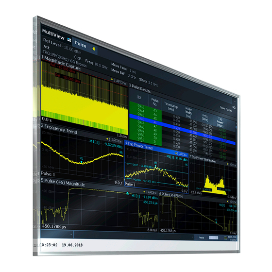
® Welcome to the Pulse Measurements Application R&S FSV3-K6 Understanding the Display Information The R&S FSV/A opens a new measurement channel for the R&S FSV3 Pulse application. The measurement is started immediately with the default settings. It can be configured in the Pulse "Overview"... - Page 13 ® Welcome to the Pulse Measurements Application R&S FSV3-K6 Understanding the Display Information = Channel bar for firmware and measurement settings 2+3 = Window title bar with diagram-specific (trace) information = Diagram area = Diagram footer with diagram-specific information, depending on measurement...
- Page 14 ® Welcome to the Pulse Measurements Application R&S FSV3-K6 Understanding the Display Information Window title bar information For each diagram, the header provides the following information: Figure 2-1: Window title bar information in the R&S FSV3 Pulse application 1 = Window number...
-
Page 15: Measurements And Result Displays
® Measurements and Result Displays R&S FSV3-K6 Pulse Parameters 3 Measurements and Result Displays During a pulse measurement, I/Q data from the input signal is captured for a specified time or for a specified record length. Pulses are detected from the signal according to specified thresholds and user-defined criteria. - Page 16 ® Measurements and Result Displays R&S FSV3-K6 Pulse Parameters Figure 3-1: Definition of the main pulse parameters and characteristic values In order to obtain these results, select the corresponding parameter in the result config- uration (see Chapter 6.1, "Result Configuration",...
- Page 17 ® Measurements and Result Displays R&S FSV3-K6 Pulse Parameters Pulse Width (ON Time)....................18 Time.........................18 Duty Ratio........................18 Duty Cycle (%)......................18 Pulse Repetition Interval....................18 Pulse Repetition Frequency (Hz).................. 19 Timestamp The time stamp uniquely identifies each pulse in the capture buffer. It is defined as the time from the capture start point to the beginning of the pulse period of the current pulse.
- Page 18 ® Measurements and Result Displays R&S FSV3-K6 Pulse Parameters Figure 3-1 Remote command: on page 295 [SENSe:]PULSe:TIMing:FALL? on page 236 CALCulate<n>:TABLe:TIMing:FALL on page 326 [SENSe:]PULSe:TIMing:FALL:LIMit? Pulse Width (ON Time) The time that the pulse remains at the top level ("ON"). This is the time between the first positive edge and the subsequent negative edge of the pulse in seconds, where the edges occur at crossings of the mid threshold.
- Page 19 ® Measurements and Result Displays R&S FSV3-K6 Pulse Parameters Remote command: on page 298 [SENSe:]PULSe:TIMing:PRI? on page 237 CALCulate<n>:TABLe:TIMing:PRI on page 326 [SENSe:]PULSe:TIMing:PRI:LIMit? Pulse Repetition Frequency (Hz) The frequency of occurrence of pulses, i.e. inverse of the "Pulse Repetition Interval"...
- Page 20 ® Measurements and Result Displays R&S FSV3-K6 Pulse Parameters Remote command: on page 282 [SENSe:]PULSe:POWer:BASE? on page 232 CALCulate<n>:TABLe:POWer:BASE on page 326 [SENSe:]PULSe:POWer:BASE:LIMit? Pulse Amplitude The difference between the "Top Power" and the "Base Power", calculated in linear power units (W). This value determines the 100% power range (amplitude). This value is converted to dBm for the Pulse Results table.
- Page 21 ® Measurements and Result Displays R&S FSV3-K6 Pulse Parameters Remote command: on page 284 [SENSe:]PULSe:POWer:MIN? on page 232 CALCulate<n>:TABLe:POWer:MIN on page 326 [SENSe:]PULSe:POWer:MIN:LIMit? Peak Power The maximum power over the entire pulse ON + OFF time Remote command: on page 283...
- Page 22 ® Measurements and Result Displays R&S FSV3-K6 Pulse Parameters on page 230 CALCulate<n>:TABLe:POWer:ADRoop[:PERCent] on page 326 [SENSe:]PULSe:POWer:ADRoop:DB:LIMit? on page 326 [SENSe:]PULSe:POWer:ADRoop[:PERCent]:LIMit? Ripple The ripple is calculated as the difference between the maximum and minimum devia- tion from the pulse top reference, within a user specified interval.
- Page 23 ® Measurements and Result Displays R&S FSV3-K6 Pulse Parameters 3.1.3 Frequency Parameters The following frequency parameters can be determined by the R&S FSV3 Pulse appli- cation. Frequency........................23 Pulse-Pulse Frequency Difference................23 Frequency Error (RMS)....................23 Frequency Error (Peak)....................23 Frequency Deviation..................... 24 Chirp Rate........................
- Page 24 ® Measurements and Result Displays R&S FSV3-K6 Pulse Parameters Frequency Deviation The frequency deviation of the currently measured pulse. The deviation is calculated as the absolute difference between the maximum and minimum frequency values within the Measurement Range. Remote command:...
- Page 25 ® Measurements and Result Displays R&S FSV3-K6 Pulse Parameters Phase Error (RMS) The RMS phase error of the currently measured pulse. The error is calculated relative to the given pulse modulation. It is not calculated at all for the Pulse Modulation type "Arbitrary".
- Page 26 ® Measurements and Result Displays R&S FSV3-K6 Pulse Parameters Figure 3-2: Envelope model parameters Each of these parameters has a time and an amplitude value. The time values are rel- ative to the pulse timestamp and displayed in seconds. The amplitude values are dis- played as power in dBm units.
- Page 27 ® Measurements and Result Displays R&S FSV3-K6 Pulse Parameters Remote command: on page 319 [SENSe:]PULSe:EMODel:RBPTime? on page 224 CALCulate<n>:TABLe:EMODel:RBPTime on page 325 [SENSe:]PULSe:EMODel:RBPTime:LIMit? Rise Low Point Time The time the amplitude reaches the Low (Proximal) Threshold in the rising edge.
- Page 28 ® Measurements and Result Displays R&S FSV3-K6 Pulse Parameters Rise High Point Level The amplitude of the High (Distal) Threshold in the rising edge. Remote command: on page 320 [SENSe:]PULSe:EMODel:RHPLevel? on page 225 CALCulate<n>:TABLe:EMODel:RHPLevel on page 325 [SENSe:]PULSe:EMODel:RHPLevel:LIMit? Rise Top Point Level The amplitude at 100 % in the rising edge.
-
Page 29: Evaluation Methods For Pulse Measurements
® Measurements and Result Displays R&S FSV3-K6 Evaluation Methods for Pulse Measurements Remote command: on page 318 [SENSe:]PULSe:EMODel:FTPTime? on page 224 CALCulate<n>:TABLe:EMODel:FTPTime on page 325 [SENSe:]PULSe:EMODel:FTPTime:LIMit? Fall Low Point Level The amplitude of the Low (Proximal) Threshold in the falling edge. - Page 30 ® Measurements and Result Displays R&S FSV3-K6 Evaluation Methods for Pulse Measurements ● Pulse Results ● Pulse Frequency ● Pulse Magnitude ● Pulse Phase The following evaluation methods are available for Pulse measurements: Magnitude Capture......................30 Marker Table ........................ 31 Parameter Distribution....................
- Page 31 ® Measurements and Result Displays R&S FSV3-K6 Evaluation Methods for Pulse Measurements Remote command: LAY:ADD:WIND '2',RIGH,MCAP see on page 247 LAYout:ADD[:WINDow]? Results: on page 270 TRACe<n>[:DATA]? Marker Table Displays a table with the current marker values for the active markers.
- Page 32 ® Measurements and Result Displays R&S FSV3-K6 Evaluation Methods for Pulse Measurements Note: Limit lines. Optionally, limit lines can be displayed in the Parameter Distribution diagram. You can drag these lines to a new position in the window. The new position is maintained, the limit check is repeated, and the results of the limit check in any active table displays are adapted.
- Page 33 ® Measurements and Result Displays R&S FSV3-K6 Evaluation Methods for Pulse Measurements Remote command: LAY:ADD:WIND '2',RIGH,PSP see on page 247 LAYout:ADD[:WINDow]? Chapter 9.12.4, "Configuring a Parameter Spectrum", on page 191 Results: on page 270 TRACe<n>[:DATA]? Parameter Trend Plots all measured parameter values from the current capture buffer (or detection range, if enabled) vs pulse number or pulse timestamp.
- Page 34 ® Measurements and Result Displays R&S FSV3-K6 Evaluation Methods for Pulse Measurements Figure 3-3: Pulse width trend display (over pulse numbers) Figure 3-4: Peak power vs pulse width scatter plot Note: Limit lines. Optionally, limit lines can be displayed in the Parameter Trend dia- gram.
- Page 35 ® Measurements and Result Displays R&S FSV3-K6 Evaluation Methods for Pulse Measurements trend displays, regardless of the displayed x-axis parameter. The "Marker" edit field is displayed when you select one of the "Marker" softkeys. However, the position displayed in the marker information area or the marker table is shown in the defined x-axis unit.
- Page 36 ® Measurements and Result Displays R&S FSV3-K6 Evaluation Methods for Pulse Measurements Remote command: LAY:ADD:WIND '2',RIGH,PIAQ see on page 247 LAYout:ADD[:WINDow]? Results: on page 280 [SENSe:]PULSe:POWer:AMPLitude:I? on page 281 [SENSe:]PULSe:POWer:AMPLitude:Q? Pulse Magnitude Displays the magnitude vs. time trace of the selected pulse. The length and alignment of the trace can be configured in the "Result Range"...
- Page 37 ® Measurements and Result Displays R&S FSV3-K6 Evaluation Methods for Pulse Measurements Pulse Phase Displays the phase vs. time trace of the selected pulse. The length and alignment of the trace can be configured in the "Result Range" dialog box (see Chapter 6.1.2,...
- Page 38 ® Measurements and Result Displays R&S FSV3-K6 Evaluation Methods for Pulse Measurements Pulse Results Displays the measured pulse parameters in a table of results. Which parameters are displayed can be configured in the "Result Configuration" (see Chapter 6.1, "Result Configuration", on page 91).
- Page 39 ® Measurements and Result Displays R&S FSV3-K6 Evaluation Methods for Pulse Measurements Note: The results of the limit check are for informational purposes only; special events such as stopping the measurement are not available. Note: Optionally, limit lines can be displayed in the...
- Page 40 ® Measurements and Result Displays R&S FSV3-K6 Evaluation Methods for Pulse Measurements The pulse-to-pulse spectrum is useful to analyze small frequency shifts which cannot be detected within an individual pulse, for example Doppler effects. Remote command: LAY:ADD? '1',RIGH,PPSP, see on page 247...
- Page 41 ® Measurements and Result Displays R&S FSV3-K6 Evaluation Methods for Pulse Measurements Result Range Spectrum Calculates a power spectrum from the captured I/Q data, within the time interval defined by the result range (see Chapter 6.1.2, "Result Range", on page 92.
-
Page 42: Measurement Basics
® Measurement Basics R&S FSV3-K6 Parameter Definitions 4 Measurement Basics Some background knowledge on basic terms and principles used in pulse measure- ments is provided here for a better understanding of the required configuration set- tings. ● Parameter Definitions....................42 ●... - Page 43 ® Measurement Basics R&S FSV3-K6 Parameter Definitions 4.1.1 Amplitude Droop The amplitude droop is calculated as the difference between the power at the begin- ning of the pulse ON time and the power at the end of the pulse ON time, divided by the pulse amplitude: ...
- Page 44 ® Measurement Basics R&S FSV3-K6 Parameter Definitions Ripple (%V) Ripple (%W) ...
-
Page 45: Pulse Detection
® Measurement Basics R&S FSV3-K6 Pulse Detection 4.1.3 Overshoot The overshoot is defined as the height of the local maximum after a rising edge, divi- ded by the pulse amplitude: Overshoot (%V) Overshoot (%W) ... - Page 46 ® Measurement Basics R&S FSV3-K6 Pulse Detection referred to as the top or 100% level, whereas the "OFF" level is referred to as the base or 0% level. Base Base Positive Negative pulse pulse A hysteresis can refine the detection process and avoid falsely interpreting unstable signals as additional pulses.
-
Page 47: Parameter Spectrum Calculation
® Measurement Basics R&S FSV3-K6 Parameter Spectrum Calculation Detection range If the capture buffer contains a large number of pulses, it can be tedious to find a par- ticular pulse for analysis. In this case, you can enable the use of a detection range instead of the entire capture buffer for analysis. - Page 48 ® Measurement Basics R&S FSV3-K6 Parameter Spectrum Calculation span for the resulting spectrum is determined automatically. However, to improve the accuracy (and performance) of the interpolation, the maximum required frequency span can be restricted further manually. Non-contiguous pulses - sections vs gaps For the non-contiguous pulse measurements described above, interpolation in the long intervals where no pulses occur distort the result.
- Page 49 ® Measurement Basics R&S FSV3-K6 Parameter Spectrum Calculation Table 4-1: FFT window functions Window type Function Rectangular The rectangular window function is in effect not a function at all, it maintains the original sampled data. This can be useful to minimize the required bandwidth; however, heavy sidelobes can occur, which do not exist in the original signal.
-
Page 50: Basics On Input From I/Q Data Files
® Measurement Basics R&S FSV3-K6 Basics on Input from I/Q Data Files Figure 4-4: Calculating a parameter spectrum for non-contiguous pulses 4.4 Basics on Input from I/Q Data Files The I/Q data to be evaluated in a particular R&S FSV/A application can not only be captured by the application itself, it can also be loaded from a file, provided it has the correct format. -
Page 51: Trace Evaluation
® Measurement Basics R&S FSV3-K6 Trace Evaluation An application note on converting Rohde & Schwarz I/Q data files is available from the Rohde & Schwarz website: 1EF85: Converting R&S I/Q data files For I/Q file input, the stored I/Q data remains available as input for any number of sub- sequent measurements. - Page 52 ® Measurement Basics R&S FSV3-K6 Trace Evaluation 4.5.1 Trace Statistics Each trace represents an analysis of the data measured in one result range. Statistical evaluations can be performed over several traces, that is, result ranges. Which ranges and how many are evaluated depends on the configuration settings.
- Page 53 ® Measurement Basics R&S FSV3-K6 Trace Evaluation The measurement point used for normalization is the same point used to determine the pulse parameter results, see Chapter 5.9.2, "Measurement Point", on page 86. Figure 4-6: Normalization of the Pulse Phase trace based on the measured pulse By default, the measurement point is the center of the pulse.
- Page 54 ® Measurement Basics R&S FSV3-K6 Trace Evaluation Normalization + averaging window Together with an Averaging Window for the measurement point, normalization based on the measured pulse can provide for a very stable pulse trace. However, the calcula- ted average value does not always coincide with the measured trace point value. So in this case, the maxhold, minhold or average traces do not necessarily pass 0 at the measurement point.
- Page 55 ® Measurement Basics R&S FSV3-K6 Trace Evaluation Figure 4-9: Normalization based on a reference pulse Note that in this case, the value at the measurement point used to determine pulse parameter results is also normalized. Thus, normalization based on a reference pulse...
-
Page 56: Configuration
® Configuration R&S FSV3-K6 Configuration Overview 5 Configuration Access: [MODE] > "Pulse" Pulse measurements require a special application on the R&S FSV/A. When you activate the Pulse application the first time, a set of parameters is passed on from the currently active application. After initial setup, the parameters for the mea- surement channel are stored upon exiting and restored upon re-entering the channel. - Page 57 ® Configuration R&S FSV3-K6 Configuration Overview In addition to the main measurement settings, the "Overview" provides quick access to the main settings dialog boxes. Thus, you can easily configure an entire measurement channel from input over processing to output and evaluation by stepping through the dialog boxes as indicated in the "Overview".
-
Page 58: Signal Description
® Configuration R&S FSV3-K6 Signal Description Select a setting in the channel bar (at the top of the measurement channel tab) to change a specific setting. Preset Channel......................58 Specific Settings for ..................... 58 Preset Channel Select the "Preset Channel" button in the lower left-hand corner of the "Overview" to restore all measurement settings in the current channel to their default values. - Page 59 ® Configuration R&S FSV3-K6 Signal Description Pulse Period........................59 Pulse Has Droop......................59 Pulse Modulation......................59 Timing Auto Mode......................60 Minimum Pulse Width, Maximum Pulse Width..............60 Min Pulse Off Time......................60 Frequency Offset Auto Mode..................60 Frequency Offset Value....................60 Chirp Rate Auto Mode....................60 Chirp Rate........................
- Page 60 ® Configuration R&S FSV3-K6 Signal Description "Arbitrary" Modulation not considered (no phase error/frequency error results available) "CW" Continuous wave modulation, i.e. only the carrier power is modulated (On/Off) For CW modulation, additional parameters are available to define the frequency offset.
-
Page 61: Input And Output Settings
® Configuration R&S FSV3-K6 Input and Output Settings Remote command: on page 145 SENSe:TRACe:MEASurement:DEFine:FREQuency:RATE:AUTO Chirp Rate Defines a known frequency chirp rate (in Hz/μs) to be used to generate an ideal pulse waveform for computing frequency and phase error parameters. This value is assumed constant for all measured pulses. - Page 62 ® Configuration R&S FSV3-K6 Input and Output Settings RF Input Protection The RF input connector of the R&S FSV/A must be protected against signal levels that exceed the ranges specified in the data sheet. Therefore, the R&S FSV/A is equipped with an overload protection mechanism for DC and signal frequencies up to 30 MHz.
- Page 63 ® Configuration R&S FSV3-K6 Input and Output Settings Impedance For some measurements, the reference impedance for the measured levels of the R&S FSV/A can be set to 50 Ω or 75 Ω. Select 75 Ω if the 50 Ω input impedance is transformed to a higher impedance using a 75 Ω...
-
Page 64: Output Settings
® Configuration R&S FSV3-K6 Input and Output Settings For details, see the R&S FSV/A I/Q Analyzer and I/Q Input User Manual. I/Q Input File State......................64 Select I/Q data file ......................64 I/Q Input File State Enables input from the selected I/Q input file. -
Page 65: Frontend Settings
® Configuration R&S FSV3-K6 Frontend Settings Noise Source Control....................65 Noise Source Control The R&S FSV/A provides a connector ("NOISE SOURCE CONTROL") with a 28 V voltage supply for an external noise source. By switching the supply voltage for an external noise source on or off in the firmware, you can enable or disable the device as required. - Page 66 ® Configuration R&S FSV3-K6 Frontend Settings 5.4.1 Frequency Settings Access: "Overview" > "Input/Frontend" > "Frequency" Or: [FREQ] Center Frequency ......................66 Center Frequency Stepsize ..................66 Frequency Offset ......................67 Center Frequency Defines the center frequency of the signal in Hertz. The allowed range of values for the center frequency depends on the frequency span.
- Page 67 ® Configuration R&S FSV3-K6 Frontend Settings Frequency Offset Shifts the displayed frequency range along the x-axis by the defined offset. This parameter has no effect on the instrument's hardware, or on the captured data or on data processing. It is simply a manipulation of the final results in which absolute fre- quency values are displayed.
- Page 68 ® Configuration R&S FSV3-K6 Frontend Settings └ Preamplifier ....................69 └ Input Coupling ....................70 └ Ext. PA Correction...................70 └ Impedance ..................... 71 Reference Level Defines the expected maximum input signal level. Signal levels above this value may not be measured correctly, which is indicated by the "IF Overload" status display.
- Page 69 ® Configuration R&S FSV3-K6 Frontend Settings NOTICE! Risk of hardware damage due to high power levels. When decreasing the attenuation manually, ensure that the power level does not exceed the maximum level allowed at the RF input, as an overload may lead to hardware damage.
- Page 70 ® Configuration R&S FSV3-K6 Frontend Settings "30 dB" The RF input signal is amplified by about 30 dB. For R&S FSV/A44 or higher models, the input signal is amplified by 30 dB if the pream- plifier is activated. In this case, the preamplifier is only available under the following conditions: ●...
-
Page 71: Trigger Settings
® Configuration R&S FSV3-K6 Trigger Settings Impedance ← Input Settings For some measurements, the reference impedance for the measured levels of the R&S FSV/A can be set to 50 Ω or 75 Ω. Select 75 Ω if the 50 Ω input impedance is transformed to a higher impedance using a 75 Ω... -
Page 72: Trigger Source
® Configuration R&S FSV3-K6 Trigger Settings Trigger 1/2........................75 └ Output Type ....................75 └ Level ....................76 └ Pulse Length ..................76 └ Send Trigger ..................76 Trigger Source Defines the trigger source. If a trigger source other than "Free Run" is set, "TRG" is displayed in the channel bar and the trigger source is indicated. -
Page 73: If Power
® Configuration R&S FSV3-K6 Trigger Settings IF Power ← Trigger Source The R&S FSV/A starts capturing data as soon as the trigger level is exceeded around the third intermediate frequency. For frequency sweeps, the third IF represents the start frequency. The trigger band- width at the third IF depends on the RBW and sweep type. -
Page 74: Trigger Offset
® Configuration R&S FSV3-K6 Trigger Settings Trigger Offset Defines the time offset between the trigger event and the start of the measurement. Offset > 0: Start of the measurement is delayed Offset < 0: Measurement starts earlier (pretrigger) Only possible for zero span (e.g. I/Q Analyzer application) and gated trigger switched off... - Page 75 ® Configuration R&S FSV3-K6 Trigger Settings Trigger 1/2 Defines the usage of the variable Trigger Input/Output connectors, where: "Trigger 2" : Trigger Input/Output connector on the front panel "Trigger 3" : Trigger 3 Input/Output connector on the rear panel Defines the usage of the variable Trigger Aux connector on the rear panel.
-
Page 76: Data Acquisition
® Configuration R&S FSV3-K6 Data Acquisition Remote command: on page 165 OUTPut<up>:TRIGger<tp>:OTYPe Level ← Output Type ← Trigger 1/2 Defines whether a high (1) or low (0) constant signal is sent to the trigger output con- nector. The trigger pulse level is always opposite to the constant signal level defined here. For example, for "Level = High", a constant high signal is output to the connector until you... - Page 77 ® Configuration R&S FSV3-K6 Data Acquisition Input from I/Q data files If the input source is an I/Q data file, most measurement settings related to data acqui- sition (attenuation, center frequency, measurement bandwidth, sample rate) cannot be changed. The measurement time can only be decreased, in order to perform measure- ments on an extract of the available data (from the beginning of the file) only.
- Page 78 ® Configuration R&S FSV3-K6 Data Acquisition "Gauss" Filter with optimized settling behavior (default) Note: For Gaussian filters whose -3dB bandwidth is large compared to the maximum I/Q bandwidth, the ideal Gaussian filter shape would exceed the maximum I/Q bandwidth at its outer edges. Thus, the actual filter only follows the ideal Gaussian filter shape in the inner range of the set I/Q bandwidth.
-
Page 79: Sweep Settings
® Configuration R&S FSV3-K6 Sweep Settings 5.7 Sweep Settings Access: [SWEEP] The sweep settings define how often data from the input signal is acquired and then evaluated. Continuous Sweep / Run Cont ..................79 Single Sweep / Run Single ...................79 Continue Single Sweep ....................80... -
Page 80: Pulse Detection
® Configuration R&S FSV3-K6 Pulse Detection If the Sequencer is off, only the evaluation for the currently displayed channel is upda- ted. Remote command: on page 179 INITiate<n>[:IMMediate] Continue Single Sweep After triggering, repeats the number of sweeps set in "Sweep Count", without deleting the trace of the last measurement. - Page 81 ® Configuration R&S FSV3-K6 Pulse Detection Or: [MEAS CONFIG] > "Data Acquisition" > "Detection" tab The pulse detection settings define the conditions under which a pulse is detected within the input signal. Reference Source......................81 Threshold........................82 Hysteresis........................82 Detection Limit......................
- Page 82 ® Configuration R&S FSV3-K6 Pulse Detection Threshold The threshold determines whether a pulse is detected or not. The top of a pulse must exceed the threshold in order to be detected. The threshold is defined in dB in relation to the defined reference, or as an absolute threshold in dBm.
-
Page 83: Pulse Measurement Settings
® Configuration R&S FSV3-K6 Pulse Measurement Settings Detection Length Defines the length of the detection range as a time in seconds. You can also change the detection length graphically by dragging one of the vertical lines ("DR") in the Mag- nitude Capture Buffer. - Page 84 ® Configuration R&S FSV3-K6 Pulse Measurement Settings Position......................... 84 Measurement Algorithm....................85 Fixed Value........................85 Ripple Portion........................85 Reference Level Unit.....................85 High (Distal) Threshold....................85 Mid (Mesial) Threshold....................85 Low (Proximal) Threshold..................... 86 Boundary........................86 Position Determines where the 100% value (from base to top) for the rise and fall time mea- surements is calculated.
- Page 85 ® Configuration R&S FSV3-K6 Pulse Measurement Settings Measurement Algorithm Defines the algorithm used to detect the pulse top level. "Mean" The arithmetic average of the measured values "Median" The level for which half the values lie above, the other half below in the histogram "Fixed"...
- Page 86 ® Configuration R&S FSV3-K6 Pulse Measurement Settings Low (Proximal) Threshold The lower threshold in percent of the pulse amplitude used to signify the end of a fall- ing or beginning of a rising signal level. Remote command: on page 173...
- Page 87 ® Configuration R&S FSV3-K6 Pulse Measurement Settings Measurement Point Reference..................87 Offset..........................87 Averaging Window......................88 Reference for Pulse-Pulse Measurements..............88 Measurement Point Reference Defines the reference which the Offset refers to. "Rise" The measurement point is defined in reference to the rising edge (mid-level crossing).
- Page 88 ® Configuration R&S FSV3-K6 Pulse Measurement Settings Remote command: on page 174 SENSe:TRACe:MEASurement:DEFine:PULSe:INSTant Averaging Window Measurement point results are averaged over a window centered at the measurement point. The length of the averaging window in seconds can be defined. A minimum length of 1 sample is enforced internally.
- Page 89 ® Configuration R&S FSV3-K6 Pulse Measurement Settings Or: [MEAS CONFIG] > "Pulse Meas" > "Meas Range" tab Some measurements are performed over a range within the pulse, for example the phase or frequency deviation. The measurement range is specified either by start and end points relative to the rising and falling edges, or as a proportion of the pulse top.
-
Page 90: Automatic Settings
® Configuration R&S FSV3-K6 Automatic Settings Absolute range (Edge): SENSe:TRACe:MEASurement:DEFine:PULSe:ESTimation:OFFSet:LEFT on page 176 SENSe:TRACe:MEASurement:DEFine:PULSe:ESTimation:OFFSet:RIGHt on page 176 5.10 Automatic Settings Access: [AUTO SET] Some settings can be adjusted by the R&S FSV/A automatically according to the cur- rent measurement settings. -
Page 91: Analysis
® Analysis R&S FSV3-K6 Result Configuration 6 Analysis After a Pulse measurement has been performed, you can analyze the results in vari- ous ways. ● Result Configuration....................91 ● Display Configuration.................... 107 ● Markers......................... 108 ● Trace Configuration....................115 ● Trace / Data Export Configuration.................120... - Page 92 ® Analysis R&S FSV3-K6 Result Configuration Linked markers in "Parameter Trend" displays the marker M1 can be linked to the selected pulse (see "Link Trend M1 to Selected Pulse" on page 113). Thus, if you select a different pulse, the marker M1 is also set to the same pulse, and vice versa.
- Page 93 ® Analysis R&S FSV3-K6 Result Configuration Automatic Range Scaling Defines whether the result range length is determined automatically according to the width of the selected pulse (see Chapter 6.1.1, "Pulse Selection", on page 91). Note: The result range is applied to all pulse-based result displays.
- Page 94 ® Analysis R&S FSV3-K6 Result Configuration Or: [MEAS CONFIG] > "Result Config" > "Result Range" tab > "Result Range Spec- trum" tab For the Result Range Spectrum display additional settings are available for the FFT. Window Type.........................94 ResBW Manual......................94 Auto........................
- Page 95 ® Analysis R&S FSV3-K6 Result Configuration RBW Auto If activated, a resolution bandwidth is selected automatically which provides a good balance between fast measurement speed and high spectral resolution. Remote command: on page 219 CALCulate<n>:RRSPectrum:AUTO 6.1.4 Result Range Frequency Configuration...
- Page 96 ® Analysis R&S FSV3-K6 Result Configuration This tab is only available for windows with a Parameter Distribution evaluation. Parameter Group......................96 X-Axis..........................96 Y-Axis..........................96 Histogram Bins......................97 Display Limit Lines......................97 Parameter Group Defines the group of parameters from which one can be selected to display the distri- bution of the measured values on the y-axis.
- Page 97 ® Analysis R&S FSV3-K6 Result Configuration Histogram Bins Number of columns on the x-axis, i.e. the number of measurement value ranges for which the occurrences are determined. Remote command: on page 188 CALCulate<n>:DISTribution:NBINs Display Limit Lines Hides or shows the limit lines in the selected Parameter Trend or Parameter Distribu- tion result display.
- Page 98 ® Analysis R&S FSV3-K6 Result Configuration This tab is only available for windows with a Parameter Spectrum evaluation. For more information on how the parameter spectrum is calculated see Chapter 4.3, "Parameter Spectrum Calculation", on page 47. Parameter Group......................98 Parameter........................
- Page 99 ® Analysis R&S FSV3-K6 Result Configuration Full Auto Determines the Parameter Spectrum settings automatically. For most measurement cases, automatic configuration should be suitable. If enabled, the individual settings are not available. Remote command: on page 192 CALCulate<n>:PSPectrum:AUTO Maximum Frequency Defines the maximum frequency span for which the Spectrum is calculated. Internally, the span is limited by the number of possible interpolation samples (100 000).
- Page 100 ® Analysis R&S FSV3-K6 Result Configuration This tab is only available for windows with a Parameter Trend result display. Parameter Group Y..................... 100 Y-Axis.......................... 100 Parameter Group X..................... 101 X-Axis..........................101 Display Style....................... 101 Display Limit Lines...................... 101 Parameter Group Y Defines the group of parameters from which one can be selected to display the trend on the y-axis.
- Page 101 ® Analysis R&S FSV3-K6 Result Configuration Parameter Group X Defines the group of parameters from which one can be selected to display the trend on the x-axis. For a description of the parameters see Chapter 3.1, "Pulse Parame- ters", on page 15.
- Page 102 ® Analysis R&S FSV3-K6 Result Configuration Note that this function only has an effect on the visibility of the lines in the graphical displays, it does not affect the limit check in general or the display of the limit check results in the table displays.
- Page 103 ® Analysis R&S FSV3-K6 Result Configuration Remote command: CALCulate<n>:TABLe:<GroupName>:<ParamName>, see Chapter 9.12.8, "Config- uring the Statistics and Parameter Tables", on page 220 ● Limit Settings for Table Displays................103 6.1.6.1 Limit Settings for Table Displays Access: "Overview" > "Result Configuration" > "Table Config" > "Limits"...
- Page 104 ® Analysis R&S FSV3-K6 Result Configuration Defining lower and upper limits for a parameter............104 Deactivating a limit check for an entire parameter group..........104 Deactivating all limit checks for all parameter groups..........104 Parameter Group Defines the group of parameters from which one can be selected to define limits. For a description of the parameters see Chapter 3.1, "Pulse...
- Page 105 ® Analysis R&S FSV3-K6 Result Configuration Automatic Grid Scaling....................105 Auto Scale Once ......................105 Absolute Scaling (Min/Max Values)................106 Relative Scaling (Reference/ per Division)..............106 └ Division....................106 └ Position....................106 └ Value...................... 106 Automatic Grid Scaling The y-axis is scaled automatically according to the current measurement settings and results (continuously).
- Page 106 ® Analysis R&S FSV3-K6 Result Configuration Absolute Scaling (Min/Max Values) Define the scaling using absolute minimum and maximum values. Remote command: on page 244 DISPlay[:WINDow<n>]:TRACe<t>:Y[:SCALe]:MAXimum on page 244 DISPlay[:WINDow<n>]:TRACe<t>:Y[:SCALe]:MINimum Relative Scaling (Reference/ per Division) Define the scaling relative to a reference value, with a specified value range per divi- sion.
-
Page 107: Display Configuration
® Analysis R&S FSV3-K6 Display Configuration Phase Unit........................107 Phase Normalization....................107 Frequency Scaling...................... 107 Phase Unit Defines the unit in which phases are displayed (degree or rad). Remote command: on page 245 UNIT:ANGLe Phase Normalization Normalizes pulse phase traces to a specific phase value. For details see "Normaliza-... -
Page 108: Markers
® Analysis R&S FSV3-K6 Markers For details on working with the SmartGrid see the R&S FSV/A Getting Started manual. 6.3 Markers Access: "Overview" > "Result Configuration" > "Markers" Or: [MKR] Markers help you analyze your measurement results by determining particular values in the diagram. - Page 109 ® Analysis R&S FSV3-K6 Markers Delta Marker 1 / Marker 2 / Marker 3 / ... Marker 16 / Norm / Delta ......109 Selected Marker ......................109 Marker State .......................109 X-value........................109 Marker Type ........................110 Reference Marker .......................110 Linking to Another Marker ..................
- Page 110 ® Analysis R&S FSV3-K6 Markers trend displays, regardless of the displayed x-axis parameter. The "Marker" edit field is displayed when you select one of the "Marker" softkeys. Remote command: on page 263 CALCulate<n>:DELTamarker<m>:X on page 260 CALCulate<n>:MARKer<m>:X Marker Type Toggles the marker type.
- Page 111 ® Analysis R&S FSV3-K6 Markers Remote command: on page 260 CALCulate<n>:MARKer<m>:TRACe Select Marker The "Select Marker" function opens a dialog box to select and activate or deactivate one or more markers quickly. Remote command: on page 259 CALCulate<n>:MARKer<m>[:STATe] on page 262 CALCulate<n>:DELTamarker<m>[:STATe]...
- Page 112 ® Analysis R&S FSV3-K6 Markers Marker Table Display Defines how the marker information is displayed. Displays the marker information in a table in a separate area beneath "On" the diagram. "Off" No separate marker table is displayed. Marker Info is active, the marker information is displayed within the diagram area.
- Page 113 ® Analysis R&S FSV3-K6 Markers Remote command: on page 264 CALCulate<n>:MARKer<m>:LINK Link Trend M1 to Selected Pulse If enabled, marker M1 in Parameter Trend displays is linked to the pulse selection. Thus, if you move the marker M1 to a different pulse, the...
- Page 114 ® Analysis R&S FSV3-K6 Markers Remote command: Chapter 9.15.3, "Positioning the Marker", on page 265 Peak Excursion Defines the minimum level value by which a signal must rise or fall so that it is identi- fied as a maximum or a minimum by the search functions.
-
Page 115: Trace Configuration
® Analysis R&S FSV3-K6 Trace Configuration Peak Search Sets the selected marker/delta marker to the maximum of the trace. If no marker is active, marker 1 is activated. Remote command: on page 266 CALCulate<n>:MARKer<m>:MAXimum[:PEAK] on page 268 CALCulate<n>:DELTamarker<m>:MAXimum[:PEAK] Search Next Peak Sets the selected marker/delta marker to the next (lower) maximum of the assigned trace. - Page 116 ® Analysis R&S FSV3-K6 Trace Configuration Trace data can also be exported to an ASCII file for further analysis. For details see Chapter 6.5, "Trace / Data Export Configuration", on page 120. You can configure up to 6 individual traces for the following result displays (see Chap- ter 6.1.2, "Result...
-
Page 117: Trace 1/Trace 2/Trace 3/Trace 4/Trace 5/Trace 6
® Analysis R&S FSV3-K6 Trace Configuration Trace 1/Trace 2/Trace 3/Trace 4/Trace 5/Trace 6 Selects the corresponding trace for configuration. The currently selected trace is high- lighted orange. For the Magnitude Capture result display, only one trace is available, which cannot be configured. -
Page 118: Evaluation
® Analysis R&S FSV3-K6 Trace Configuration Remote command: DISPlay[:WINDow<n>][:SUBWindow<w>]:TRACe<t>:MODE:HCONtinuous on page 255 Evaluation Defines which signal component (I/Q) is evaluated in which trace for the Pulse I and Q result display. This setting is not available for any other result displays. By default, the I component is displayed by trace 1, while the Q component is displayed by trace 4. -
Page 119: Normalization
® Analysis R&S FSV3-K6 Trace Configuration Remote command: on page 258 [SENSe:]SWEep:POINts Normalization Enables or disables normalization of the trace in reference to the measured pulse or a reference pulse. For details see Chapter 4.5.2, "Normalizing Traces", on page 52. -
Page 120: Trace / Data Export Configuration
® Analysis R&S FSV3-K6 Trace / Data Export Configuration 6.5 Trace / Data Export Configuration Access: "Save" > "Export" > "Trace Export Configuration" Or: [TRACE] > "Trace Config" > "Trace / Data Export" The R&S FSV/A provides various evaluation methods for the results of the performed measurements. -
Page 121: Export Functions
® Analysis R&S FSV3-K6 Export Functions Include Instrument & Measurement Settings Includes additional instrument and measurement settings in the header of the export file for result data. Remote command: on page 328 FORMat:DEXPort:HEADer Trace to Export Defines an individual trace to be exported to a file. - Page 122 ® Analysis R&S FSV3-K6 Export Functions └ Decimal Separator ..................123 └ Export table to ASCII File ................123 Export Trace to ASCII File ..................124 Trace Export Configuration..................124 I/Q Export ........................124 └ Export Range ....................125 Export table to ASCII File Opens a file selection dialog box and saves the selected result table in ASCII format (.DAT) to the specified file and directory.
-
Page 123: Decimal Separator
® Analysis R&S FSV3-K6 Export Functions Columns to Export ← Table Export Configuration Defines which of the result table columns are to be included in the export file. "Visible" Only the currently visible columns in the result display are exported. -
Page 124: Export Trace To Ascii File
® Analysis R&S FSV3-K6 Export Functions (See also Chapter 6.5, "Trace / Data Export Configuration", on page 120.) Note: Secure user mode. In secure user mode, settings that are stored on the instrument are stored to volatile memory, which is restricted to 256 MB. Thus, a "memory limit reached" error can occur although the hard disk indicates that storage space is still available. -
Page 125: Export Range
® Analysis R&S FSV3-K6 Export Functions For details, see "Protecting Data Using the Secure User Mode" in the "Data Manage- ment" section of the R&S FSV3000/ FSVA3000 base unit user manual. Remote command: on page 331 MMEMory:STORe<n>:IQ:STATe on page 330 MMEMory:STORe<n>:IQ:COMMent... -
Page 126: Export Functions
® Export Functions R&S FSV3-K6 7 Export Functions Access: "Save" > "Export" The standard data management functions (e.g. saving or loading instrument settings) that are available for all R&S FSV/A applications are not described here. See the R&S FSV/A User Manual for a description of the standard functions. - Page 127 ® Export Functions R&S FSV3-K6 Columns to Export ← Table Export Configuration Defines which of the result table columns are to be included in the export file. "Visible" Only the currently visible columns in the result display are exported. "All"...
- Page 128 ® Export Functions R&S FSV3-K6 (See also Chapter 6.5, "Trace / Data Export Configuration", on page 120.) Note: Secure user mode. In secure user mode, settings that are stored on the instrument are stored to volatile memory, which is restricted to 256 MB. Thus, a "memory limit reached" error can occur although the hard disk indicates that storage space is still available.
- Page 129 ® Export Functions R&S FSV3-K6 For details, see "Protecting Data Using the Secure User Mode" in the "Data Manage- ment" section of the R&S FSV3000/ FSVA3000 base unit user manual. Remote command: on page 331 MMEMory:STORe<n>:IQ:STATe on page 330 MMEMory:STORe<n>:IQ:COMMent Export Range ←...
-
Page 130: How To Perform Measurements In The Pulse Application
® How to Perform Measurements in the Pulse Application R&S FSV3-K6 How to Perform a Standard Pulse Measurement 8 How to Perform Measurements in the Pulse Application The following step-by-step instructions demonstrate how to perform a Pulse measure- ment with the R&S FSV/A-K6 option. -
Page 131: How To Configure A Limit Check For A Pulse Measurement
® How to Perform Measurements in the Pulse Application R&S FSV3-K6 How to Configure a Limit Check for a Pulse Measurement 11. Select the "Result Config" button in the "Overview" to configure which data is dis- played in the individual result displays, and other settings for specific evaluation methods. -
Page 132: How To Export Table Data
® How to Perform Measurements in the Pulse Application R&S FSV3-K6 How to Export Table Data 7. Repeat step 4 step 6 for each parameter you want to perform a limit check on. The measured values and all newly measured values for the specified parameter are compared to the defined limit values. - Page 133 ® How to Perform Measurements in the Pulse Application R&S FSV3-K6 How to Export Table Data 5. Select the "ASCII Table Export" softkey. 6. In the file selection dialog box, select the storage location and file name for the export file.
-
Page 134: Remote Commands For Pulse Measurements
® Remote Commands for Pulse Measurements R&S FSV3-K6 Introduction 9 Remote Commands for Pulse Measure- ments The following commands are required to perform measurements in the Pulse applica- tion in a remote environment. The R&S FSV/A must already be set up for remote oper- ation in a network as described in the base unit manual. - Page 135 ® Remote Commands for Pulse Measurements R&S FSV3-K6 Introduction way, others work in two ways (setting and query). If not indicated otherwise, the com- mands can be used for settings and queries. The syntax of a SCPI command consists of a header and, in most cases, one or more parameters.
- Page 136 ® Remote Commands for Pulse Measurements R&S FSV3-K6 Introduction ● Manual operation If the result of a remote command can also be achieved in manual operation, a link to the description is inserted. 9.1.2 Long and Short Form The keywords have a long and a short form. You can use either the long or the short form, but no other abbreviations of the keywords.
- Page 137 ® Remote Commands for Pulse Measurements R&S FSV3-K6 Introduction Example: Without a numeric suffix in the optional keyword: [SENSe:]FREQuency:CENTer is the same as FREQuency:CENTer With a numeric suffix in the optional keyword: DISPlay[:WINDow<1...4>]:ZOOM:STATe DISPlay:ZOOM:STATe ON enables the zoom in window 1 (no suffix).
- Page 138 ® Remote Commands for Pulse Measurements R&S FSV3-K6 Introduction Values exceeding the resolution of the instrument are rounded up or down. If the number you have entered is not supported (e.g. in case of discrete steps), the command returns an error.
-
Page 139: Common Suffixes
® Remote Commands for Pulse Measurements R&S FSV3-K6 Common Suffixes 9.1.6.3 Character Data Character data follows the syntactic rules of keywords. You can enter text using a short or a long form. For more information see Chapter 9.1.2, "Long and Short Form",... -
Page 140: Activating Pulse Measurements
® Remote Commands for Pulse Measurements R&S FSV3-K6 Activating Pulse Measurements Suffix Value range Description <t> Trace <li> 1 to 8 Limit line 9.3 Activating Pulse Measurements Pulse measurements require a special application on the R&S FSV/A. The measure- ment is started immediately with the default settings. - Page 141 ® Remote Commands for Pulse Measurements R&S FSV3-K6 Activating Pulse Measurements INSTrument:CREate:REPLace <ChannelName1>,<ChannelType>,<ChannelName2> This command replaces a channel with another one. Setting parameters: <ChannelName1> String containing the name of the channel you want to replace. <ChannelType> Channel type of the new channel.
- Page 142 NB-IoT Noise Figure Measure- NOISE Noise ments Phase Noise (R&S FSV3- PNOISE Phase Noise K40) Pulse (R&S FSV3-K6) PULSE Pulse Vector Signal Analysis DDEM (VSA, R&S FSV3-K70) WLAN (R&S FSV3-K91) WLAN WLAN Note: the default channel name is also listed in the table. If the specified name for a new channel already exists, the default name, extended by a sequential number, is used for the new channel.
-
Page 143: Signal Description
® Remote Commands for Pulse Measurements R&S FSV3-K6 Signal Description Usage: Setting only INSTrument[:SELect] <ChannelType> This command activates a new measurement channel with the defined channel type, or selects an existing measurement channel with the specified name. See also on page 140. - Page 144 ® Remote Commands for Pulse Measurements R&S FSV3-K6 Signal Description Parameters: <State> ON | OFF | 0 | 1 *RST: Manual operation: "Timing Auto Mode" on page 60 SENSe:TRACe:MEASurement:DEFine:DURation:MAX <PulseMaxWidth> Defines a maximum pulse width; pulses outside this range are not detected. The avail- able value range is 50ns to 100s, but may be restricted further by the sample rate.
- Page 145 ® Remote Commands for Pulse Measurements R&S FSV3-K6 Signal Description SENSe:TRACe:MEASurement:DEFine:FREQuency:OFFSet:AUTO <State> If enabled, the frequency offset is estimated automatically for each individual pulse. Parameters: <State> ON | OFF | 0 | 1 *RST: Manual operation: "Frequency Offset Auto Mode"...
-
Page 146: Input/Output Settings
® Remote Commands for Pulse Measurements R&S FSV3-K6 Input/Output Settings Linear FM (fixed value) *RST: Manual operation: "Pulse Modulation" on page 59 SENSe:TRACe:MEASurement:DEFine:PULSe:PERiod <PulsePeriod> This command defines how a pulse is detected. Parameters: <PulsePeriod> HL | LH The pulse period begins with the falling edge of the preceding pulse and ends with the falling edge of the current pulse. - Page 147 ® Remote Commands for Pulse Measurements R&S FSV3-K6 Input/Output Settings (For details on the status register see the R&S FSV3000/ FSVA3000 base unit user manual). The command works only if the overload condition has been eliminated first. Suffix: <ip> 1 | 2...
- Page 148 ® Remote Commands for Pulse Measurements R&S FSV3-K6 Input/Output Settings INPut<ip>:FILTer:YIG[:STATe] <State> Suffix: <ip> 1 | 2 irrelevant Parameters: <State> ON | OFF | 0 | 1 *RST: 1 (0 for I/Q Analyzer, GSM, VSA, Pulse, Amplifier, Transient Analysis, DOCSIS and MC Group Delay...
- Page 149 ® Remote Commands for Pulse Measurements R&S FSV3-K6 Input/Output Settings Manual operation: " Radio Frequency State " on page 62 "I/Q Input File State" on page 64 9.5.2 Input from I/Q Data Files The input for measurements can be provided from I/Q data files. The commands required to configure the use of such files are described here.
- Page 150 ® Remote Commands for Pulse Measurements R&S FSV3-K6 Input/Output Settings Configuring trigger input/output is described in Chapter 9.7.2, "Configuring the Trigger Output", on page 164..................150 DIAGnostic:SERVice:NSOurce ....................150 OUTPut<up>:IF:STATe ..................... 150 OUTPut<up>:VIDeo:STATe ....................151 SYSTem:SPEaker[:STATe] ..................151 SYSTem:SPEaker:MAXVolume ....................151 SYSTem:SPEaker:MUTE ....................
- Page 151 ® Remote Commands for Pulse Measurements R&S FSV3-K6 Input/Output Settings Suffix: <up> 1..n Parameters: <State> ON | OFF | 0 | 1 OFF | 0 Switches the function off ON | 1 Switches the function on *RST: Example: OUTP:VID:STAT ON SYSTem:SPEaker[:STATe] <State>...
-
Page 152: Frontend Configuration
® Remote Commands for Pulse Measurements R&S FSV3-K6 Frontend Configuration SYSTem:SPEaker:VOLume <Volume> This command defines the volume of the built-in loudspeaker for demodulated signals. This setting is maintained for all applications. The command is available in the time domain in Spectrum mode and in Analog Demodulation mode. - Page 153 ® Remote Commands for Pulse Measurements R&S FSV3-K6 Frontend Configuration [SENSe:]FREQuency:CENTer:STEP <StepSize> This command defines the center frequency step size. You can increase or decrease the center frequency quickly in fixed steps using the SENS:FREQ UP AND SENS:FREQ DOWN commands, see [SENSe:]FREQuency: on page 152.
- Page 154 ® Remote Commands for Pulse Measurements R&S FSV3-K6 Frontend Configuration 9.6.2 Amplitude Settings The following commands are required to configure the amplitude settings in a remote environment. Useful commands for amplitude settings described elsewhere: ● on page 147 INPut<ip>:COUPling ●...
- Page 155 ® Remote Commands for Pulse Measurements R&S FSV3-K6 Frontend Configuration DISPlay[:WINDow<n>]:TRACe<t>:Y[:SCALe]:RLEVel:OFFSet <Offset> This command defines a reference level offset (for all traces in all windows). Suffix: <n> irrelevant <t> irrelevant Parameters: <Offset> Range: -200 dB to 200 dB *RST: Default unit: DB...
- Page 156 ® Remote Commands for Pulse Measurements R&S FSV3-K6 Frontend Configuration Suffix: <ip> 1 | 2 irrelevant Parameters: <State> ON | OFF | 0 | 1 OFF | 0 Switches the function off ON | 1 Switches the function on *RST:...
- Page 157 ® Remote Commands for Pulse Measurements R&S FSV3-K6 Frontend Configuration 9.6.3 Configuring the Attenuation ....................157 INPut<ip>:ATTenuation ..................157 INPut<ip>:ATTenuation:AUTO ......................158 INPut<ip>:EATT ....................158 INPut<ip>:EATT:AUTO ....................158 INPut<ip>:EATT:STATe INPut<ip>:ATTenuation <Attenuation> This command defines the total attenuation for RF input. If an electronic attenuator is available and active, the command defines a mechanical attenuation (see on page 158).
- Page 158 ® Remote Commands for Pulse Measurements R&S FSV3-K6 Frontend Configuration INPut<ip>:EATT <Attenuation> This command defines an electronic attenuation manually. Automatic mode must be switched off (INP:EATT:AUTO OFF, see on page 158). INPut<ip>:EATT:AUTO If the current reference level is not compatible with an attenuation that has been set manually, the command also adjusts the reference level.
-
Page 159: Triggering Measurements
® Remote Commands for Pulse Measurements R&S FSV3-K6 Triggering Measurements Suffix: <ip> 1 | 2 irrelevant Parameters: <State> ON | OFF | 0 | 1 OFF | 0 Switches the function off ON | 1 Switches the function on *RST:... - Page 160 ® Remote Commands for Pulse Measurements R&S FSV3-K6 Triggering Measurements Parameters: <DropoutTime> Dropout time of the trigger. Range: 0 s to 10.0 s *RST: Default unit: S Manual operation: " Drop-Out Time " on page 73 TRIGger[:SEQuence]:HOLDoff[:TIME] <Offset> Defines the time offset between the trigger event and the start of the measurement.
- Page 161 ® Remote Commands for Pulse Measurements R&S FSV3-K6 Triggering Measurements Example: TRIG:SOUR IFP Sets the IF power trigger source. TRIG:IFP:HYST 10DB Sets the hysteresis limit value. Manual operation: " Hysteresis " on page 74 TRIGger<tp>[:SEQuence]:LEVel[:EXTernal<port>] <TriggerLevel> This command defines the level the external signal must exceed to cause a trigger event.
- Page 162 ® Remote Commands for Pulse Measurements R&S FSV3-K6 Triggering Measurements TRIGger[:SEQuence]:LEVel:IQPower <TriggerLevel> This command defines the magnitude the I/Q data must exceed to cause a trigger event. Note that any RF attenuation or preamplification is considered when the trigger level is analyzed.
- Page 163 ® Remote Commands for Pulse Measurements R&S FSV3-K6 Triggering Measurements NEGative Triggers when the signal drops to the trigger level (falling edge). *RST: POSitive Example: TRIG:SLOP NEG Manual operation: " Slope " on page 74 TRIGger[:SEQuence]:SOURce <Source> This command selects the trigger source.
- Page 164 ® Remote Commands for Pulse Measurements R&S FSV3-K6 Triggering Measurements Manual operation: "Trigger Source" on page 72 " Free Run " on page 72 "External Trigger 1/2" on page 72 " I/Q Power " on page 72 " IF Power "...
- Page 165 ® Remote Commands for Pulse Measurements R&S FSV3-K6 Triggering Measurements <tp> Selects the trigger port to which the output is sent. 2 = trigger port 2 (front) 3 = trigger port 3 (rear) 2 = Trigger 2 Input / Output Parameters: <Level>...
-
Page 166: Data Acquisition
® Remote Commands for Pulse Measurements R&S FSV3-K6 Data Acquisition Manual operation: " Send Trigger " on page 76 OUTPut:TRIGger<tp>:PULSe:LENGth <Length> This command defines the length of the pulse generated at the trigger output. Suffix: <tp> Selects the trigger port to which the output is sent. - Page 167 ® Remote Commands for Pulse Measurements R&S FSV3-K6 Data Acquisition [SENSe:]BANDwidth:DEMod:TYPE <FilterType> [SENSe:]BWIDth:DEMod:TYPE <FilterType> This command defines the type of demodulation filter to be used. For information on supported filter bandwidths see the data sheet. Parameters: <FilterType> FLAT | GAUSs...
-
Page 168: Pulse Detection
® Remote Commands for Pulse Measurements R&S FSV3-K6 Pulse Detection Return values: <SampleRate> Current sample rate used by the application. Usage: Query only [SENSe:]SWEep:TIME <Time> This command defines the measurement time. It automatically decouples the time from any other settings. - Page 169 ® Remote Commands for Pulse Measurements R&S FSV3-K6 Pulse Detection OFF | 0 Switches the function off ON | 1 Switches the function on *RST: Manual operation: "Detection Limit" on page 82 [SENSe:]DETect:LIMit:COUNt <MaxPulseCount> Defines the maximum number of pulses to be detected.
- Page 170 ® Remote Commands for Pulse Measurements R&S FSV3-K6 Pulse Detection [SENSe:]DETect:RANGe:LENGth <DetectionLength> Defines the length of the detection range as a time in seconds. This command is only available for [SENSe:]DETect:RANGe Parameters: <DetectionLength> Default unit: S Example: SENS:DET:RANG ON SENS:DET:RANG:STAR 10ms...
-
Page 171: Configuring The Pulse Measurement
® Remote Commands for Pulse Measurements R&S FSV3-K6 Configuring the Pulse Measurement [SENSe:]DETect:THReshold <Level> The threshold determines whether a pulse is detected or not. The top of a pulse must exceed the threshold in order to be detected. The threshold is defined in relation to the reference defined by [SENSe:]DETect:REFerence. - Page 172 ® Remote Commands for Pulse Measurements R&S FSV3-K6 Configuring the Pulse Measurement Example: SENS:TRAC:MEAS:ALG PEAK Manual operation: "Measurement Algorithm" on page 85 SENSe:TRACe:MEASurement:DEFine:AMPLitude:UNIT <Unit> Defines the unit of the pulse amplitude values, i.e. whether magnitude (V) or power (W, dBm) values are used to determine the threshold levels for fall and rise times.
- Page 173 ® Remote Commands for Pulse Measurements R&S FSV3-K6 Configuring the Pulse Measurement Parameters: <Portion> percentage Range: 0 to 100 *RST: Manual operation: "Ripple Portion" on page 85 SENSe:TRACe:MEASurement:DEFine:TOP:FIXed <TopFixed> Defines the top power level value to be used by the pulse measurement algorithm.
- Page 174 ® Remote Commands for Pulse Measurements R&S FSV3-K6 Configuring the Pulse Measurement Parameters: <Threshold> percentage Range: 0 to 100 *RST: Manual operation: "Mid (Mesial) Threshold" on page 85 9.10.2 Measurement Point .............174 SENSe:TRACe:MEASurement:DEFine:PULSe:INSTant ........174 SENSe:TRACe:MEASurement:DEFine:PULSe:INSTant:AWINdow ........174 SENSe:TRACe:MEASurement:DEFine:PULSe:INSTant:REFerence ..........175 SENSe:TRACe:MEASurement:DEFine:PULSe:REFerence ........
- Page 175 ® Remote Commands for Pulse Measurements R&S FSV3-K6 Configuring the Pulse Measurement FALL The measurement point is defined in reference to the falling edge (mid-level crossing). *RST: CENTer Manual operation: "Measurement Point Reference" on page 87 SENSe:TRACe:MEASurement:DEFine:PULSe:REFerence <RefPulseNumber> Selects a particular pulse to be used as a reference for relative pulse parameters (see SENSe:TRACe:MEASurement:DEFine:PULSe:REFerence:POSition on page 175).
- Page 176 ® Remote Commands for Pulse Measurements R&S FSV3-K6 Configuring the Pulse Measurement Example: SENS:TRAC:MEAS:DEF:PULS:SEL 2 SENS:TRAC:MEAS:DEF:PULS:REF:POS SEL All relative pulse results are based on the currently selected pulse number 2. Example: SENS:TRAC:MEAS:DEF:PULS:REF:POS BPUL SENS:TRAC:MEAS:DEF:PULS:REF 1 For each pulse evaluation, the previous pulse is used as a refer- ence.
-
Page 177: Configuring And Performing Sweeps
® Remote Commands for Pulse Measurements R&S FSV3-K6 Configuring and Performing Sweeps Manual operation: "Reference, Length, Offset" on page 89 SENSe:TRACe:MEASurement:DEFine:PULSe:ESTimation:REFerence <Reference> Defines the reference for the measurement range definition. Depending on the selected reference type, an additional setting is available to define the range. -
Page 178: Abort
® Remote Commands for Pulse Measurements R&S FSV3-K6 Configuring and Performing Sweeps ABORt This command aborts the measurement in the current channel and resets the trigger system. To prevent overlapping execution of the subsequent command before the measure- ment has been aborted successfully, use the *OPC? or *WAI command after ABOR and before the next command. -
Page 179: Initiate
® Remote Commands for Pulse Measurements R&S FSV3-K6 Configuring and Performing Sweeps INITiate<n>:CONTinuous <State> This command controls the measurement mode for an individual channel. Note that in single measurement mode, you can synchronize to the end of the mea- surement with *OPC, *OPC? or *WAI. In continuous measurement mode, synchroniza- tion to the end of the measurement is not possible.:Continuous -
Page 180: Initiate:sequencer:abort
® Remote Commands for Pulse Measurements R&S FSV3-K6 Configuring and Performing Sweeps Suffix: <n> irrelevant Manual operation: " Single Sweep / Run Single " on page 79 INITiate:SEQuencer:ABORt This command stops the currently active sequence of measurements. The Sequencer itself is not deactivated, so you can start a new sequence immediately using on page 180. -
Page 181: [Sense:]Sweep:count
® Remote Commands for Pulse Measurements R&S FSV3-K6 Configuring and Performing Sweeps CONTinuous The measurements in each active channel are performed one after the other, repeatedly (regardless of the channel's sweep mode), in the same order, until the Sequencer is stopped. -
Page 182: Configuring The Results
® Remote Commands for Pulse Measurements R&S FSV3-K6 Configuring the Results [SENSe:]SWEep:COUNt:CURRent? This query returns the current number of started sweeps or measurements. This com- mand is only available if a sweep count value is defined and the instrument is in single sweep mode. - Page 183 ® Remote Commands for Pulse Measurements R&S FSV3-K6 Configuring the Results ● Configuring a Parameter Trend................200 ● Configuring a Result Range Spectrum..............219 ● Configuring the Statistics and Parameter Tables..........220 ● Configuring Limit Checks..................238 ● Configuring the Y-Axis Scaling and Units..............242...
- Page 184 ® Remote Commands for Pulse Measurements R&S FSV3-K6 Configuring the Results LEFT The result range starts at the pulse center or selected edge. CENTer The result range is centered around the pulse center or selected edge. RIGHt The result range ends at the pulse center or selected edge.
- Page 185 ® Remote Commands for Pulse Measurements R&S FSV3-K6 Configuring the Results SENSe:TRACe:MEASurement:DEFine:RRANge:REFerence <Reference> Specifies the reference point used to define the result range. Parameters: <Reference> RISE The result range is defined in reference to the rising edge. CENTer The result range is defined in reference to the center of the pulse top.
- Page 186 ® Remote Commands for Pulse Measurements R&S FSV3-K6 Configuring the Results RLPTime Rise Low Point Time RMPTime Rise Mid Point Time RHPTime Rise High Point Time RTPTime Rise Top Point Time RLPLevel Rise Low Point Level RMPLevel Rise Mid Point Level...
- Page 187 ® Remote Commands for Pulse Measurements R&S FSV3-K6 Configuring the Results CALCulate<n>:DISTribution:FREQuency <XAxis>, <YAxis> Configures the Parameter Distribution result display. Suffix: <n> 1..n Window Setting parameters: <XAxis> POINt | PPFRequency | RERRor | PERRor | DEViation | CRATe Pulse parameter to be displayed on the x-axis. For a description of the available parameters see Chapter 3.1.3, "Frequency...
- Page 188 ® Remote Commands for Pulse Measurements R&S FSV3-K6 Configuring the Results Suffix: <n> 1..n Window Parameters: <State> ON | OFF | 1 | 0 *RST: Example: CALC:DIST:LLIN ON Manual operation: "Display Limit Lines" on page 97 CALCulate<n>:DISTribution:NBINs <# bins> This command sets the number of bins used to calculate the historgram Suffix: <n>...
- Page 189 ® Remote Commands for Pulse Measurements R&S FSV3-K6 Configuring the Results Parameter to be displayed on the y-axis. COUNt Number of pulses in which the parameter value occurred. OCCurrence Percentage of all measured pulses in which the parameter value occurred.
- Page 190 ® Remote Commands for Pulse Measurements R&S FSV3-K6 Configuring the Results ADDB Droop in dB RPERcent Ripple in % Ripple in dB OPERcent Overshoot in % Overshoot in dB POINt Pulse power measured at measurement point PPRatio Pulse-to-Pulse Power Difference *RST: <YAxis>...
- Page 191 ® Remote Commands for Pulse Measurements R&S FSV3-K6 Configuring the Results FALL Fall Time PWIDth Pulse Width (ON Time) Off Time DRATio Duty Ratio DCYCle Duty Cycle (%) Pulse Repetition Interval Pulse Repetition Frequency (Hz) *RST: RISE <YAxis> COUNt | OCCurrence Parameter to be displayed on the y-axis.
- Page 192 ® Remote Commands for Pulse Measurements R&S FSV3-K6 Configuring the Results ................196 CALCulate<n>:PSPectrum:STHReshold ................... 197 CALCulate<n>:PSPectrum:TIMing ................197 CALCulate<n>:PSPectrum:WINDow CALCulate<n>:PSPectrum:AUTO <State> Enables or disables automatic configuration for Parameter Spectrum displays. If enabled, the commands for individual settings are not available.
- Page 193 ® Remote Commands for Pulse Measurements R&S FSV3-K6 Configuring the Results RHPTime Rise High Point Time RTPTime Rise Top Point Time RLPLevel Rise Low Point Level RMPLevel Rise Mid Point Level RHPLevel Rise High Point Level RTPLevel Rise Top Point Level...
- Page 194 ® Remote Commands for Pulse Measurements R&S FSV3-K6 Configuring the Results PPFRequency Pulse-Pulse Frequency Difference RERRor Frequency Error (RMS) PERRor Frequency Error (Peak) DEViation Frequency Deviation CRATe Chirp Rate *RST: POINt Manual operation: "Parameter" on page 98 CALCulate<n>:PSPectrum:GTHReshold <GapThreshold> Defines the minimum time that must pass before a gap is detected as such.
- Page 195 ® Remote Commands for Pulse Measurements R&S FSV3-K6 Configuring the Results Pulse parameter to be displayed on the x-axis. For a description of the available parameters see Chapter 3.1.4, "Phase Parame- ters", on page 24. POINt Pulse phase at measurement point...
- Page 196 ® Remote Commands for Pulse Measurements R&S FSV3-K6 Configuring the Results PAVG Peak-to-Average Tx Power Ratio PMIN Peak-to-Min Power Ratio ADPercent Droop in % ADDB Droop in dB RPERcent Ripple in % Ripple in dB OPERcent Overshoot in % Overshoot in dB...
- Page 197 ® Remote Commands for Pulse Measurements R&S FSV3-K6 Configuring the Results Parameters: <Threshold> Minimum section size as a percentage of the block size (see on page 192) CALCulate<n>:PSPectrum:BLOCksize Range: 0 to 100 *RST: Manual operation: "Section Threshold" on page 99 CALCulate<n>:PSPectrum:TIMing <Param>...
- Page 198 ® Remote Commands for Pulse Measurements R&S FSV3-K6 Configuring the Results Suffix: <n> 1..n Window Setting parameters: <WindowType> RECTangle | BARTlett | HAMMing | HANNing | BLACkman *RST: BLACkman Manual operation: "Window Type" on page 99 9.12.5 Configuring a Pulse-Pulse Spectrum The pulse-to-pulse spectrum evaluation allows you to visualize the spectrum of I and Q-based results for all measured pulses within the current capture buffer.
- Page 199 ® Remote Commands for Pulse Measurements R&S FSV3-K6 Configuring the Results Suffix: <n> 1..n Window Parameters: <GapThreshold> Range: minimum spacing between pulses to meas time Default unit: S Example: CALC:PPSP:GTHR 100us CALCulate<n>:PPSPectrum:MAXFrequency <MaxFrequency> Defines the maximum frequency span for which the Spectrum is calculated. Internally, the span is limited by the number of possible interpolation samples (100 000).
- Page 200 ® Remote Commands for Pulse Measurements R&S FSV3-K6 Configuring the Results Parameters: <Threshold> Minimum section size as a percentage of the block size (see on page 192) CALCulate<n>:PSPectrum:BLOCksize Range: 0 to 100 *RST: Example: CALC:PSPS:STHR 0.1 CALCulate<n>:PPSPectrum:WINDow <WindowType> Defines the used FFT window type for pulse-to-pulse spectrum displays.
- Page 201 ® Remote Commands for Pulse Measurements R&S FSV3-K6 Configuring the Results CALCulate<n>:TRENd:DSTYle <Type> Suffix: <n> 1..n Window Parameters: <Type> AUTO | DOTS | LINes | DLINes Manual operation: "Display Style" on page 101 CALCulate<n>:TRENd:EMODel <YAxis>, <XAxis> Configures the Parameter Trend result display for envelope model trends. This com- mand defines both x-axis and y-axis parameters in one step.
- Page 202 ® Remote Commands for Pulse Measurements R&S FSV3-K6 Configuring the Results FBPTime Fall Base Point Time FLPTime Fall Low Point Time FMPTime Fall Mid Point Time FHPTime Fall High Point Time FTPTime Fall Top Point Time FLPLevel Fall Low Point Level...
- Page 203 ® Remote Commands for Pulse Measurements R&S FSV3-K6 Configuring the Results Pulse Repetition Frequency (Hz) *RST: PNUMber Usage: Setting only CALCulate<n>:TRENd:EMODel:X <XAxis> Configures the x-axis of the Parameter Trend result display. The y-axis is configured using the CALCulate<n>:TRENd:<GroupName>:Y com- mands.
- Page 204 ® Remote Commands for Pulse Measurements R&S FSV3-K6 Configuring the Results FTPTime Fall Top Point Time FLPLevel Fall Low Point Level FMPLevel Fall Mid Point Level FHPLevel Fall High Point Level FTPLevel Fall Top Point Level Usage: Setting only CALCulate<n>:TRENd:EMODel:Y <YAxis>...
- Page 205 ® Remote Commands for Pulse Measurements R&S FSV3-K6 Configuring the Results FBPTime Fall Base Point Time FLPTime Fall Low Point Time FMPTime Fall Mid Point Time FHPTime Fall High Point Time FTPTime Fall Top Point Time FLPLevel Fall Low Point Level...
- Page 206 ® Remote Commands for Pulse Measurements R&S FSV3-K6 Configuring the Results PERRor Frequency Error (Peak) DEViation Frequency Deviation CRATe Chirp Rate *RST: POINt <XAxis> PNUMber | TSTamp | SETTling | RISE | FALL | PWIDth | OFF | DRATio | DCYCle | PRI | PRF Pulse parameter to be displayed on the x-axis.
- Page 207 ® Remote Commands for Pulse Measurements R&S FSV3-K6 Configuring the Results The y-axis is configured using the CALCulate<n>:TRENd:<GroupName>:Y com- mands. Suffix: <n> 1..n Window Setting parameters: <XAxis> POINt | PPFRequency | RERRor | PERRor | DEViation | CRATe Pulse parameter to be displayed on the x-axis. For a description of the available parameters see Chapter 3.1.3, "Frequency...
- Page 208 ® Remote Commands for Pulse Measurements R&S FSV3-K6 Configuring the Results PPFRequency Pulse-Pulse Frequency Difference RERRor Frequency Error (RMS) PERRor Frequency Error (Peak) DEViation Frequency Deviation CRATe Chirp Rate *RST: POINt Usage: Setting only Manual operation: "Y-Axis" on page 100 CALCulate<n>:TRENd:LLINes[:STATe] <State>...
- Page 209 ® Remote Commands for Pulse Measurements R&S FSV3-K6 Configuring the Results Suffix: <n> 1..n Window Setting parameters: <YAxis> POINt | PPPHase | RERRor | PERRor | DEViation Pulse parameter to be displayed on the y-axis. For a description of the available parameters see Chapter 3.1.4, "Phase Parame-...
- Page 210 ® Remote Commands for Pulse Measurements R&S FSV3-K6 Configuring the Results Pulse Repetition Interval Pulse Repetition Frequency (Hz) *RST: PNUMber Usage: Setting only CALCulate<n>:TRENd:PHASe:X <XAxis> Configures the x-axis of the Parameter Trend result display. The y-axis is configured using the CALCulate<n>:TRENd:<GroupName>:Y com- mands.
- Page 211 ® Remote Commands for Pulse Measurements R&S FSV3-K6 Configuring the Results Suffix: <n> 1..n Window Setting parameters: <YAxis> POINt | PPPHase | RERRor | PERRor | DEViation Pulse parameter to be displayed on the y-axis. For a description of the available parameters see Chapter 3.1.4, "Phase Parame-...
- Page 212 ® Remote Commands for Pulse Measurements R&S FSV3-K6 Configuring the Results AMPLitude Pulse Amplitude Average ON Power Average Tx Power Minimum Power Peak Power Peak-to-Avg ON Power Ratio PAVG Peak-to-Average Tx Power Ratio PMIN Peak-to-Min Power Ratio ADPercent Droop in %...
- Page 213 ® Remote Commands for Pulse Measurements R&S FSV3-K6 Configuring the Results SETTling Settling Time RISE Rise Time FALL Fall Time PWIDth Pulse Width (ON Time) Off Time DRATio Duty Ratio DCYCle Duty Cycle (%) Pulse Repetition Interval Pulse Repetition Frequency (Hz)
- Page 214 ® Remote Commands for Pulse Measurements R&S FSV3-K6 Configuring the Results Average Tx Power Minimum Power Peak Power Peak-to-Avg ON Power Ratio PAVG Peak-to-Average Tx Power Ratio PMIN Peak-to-Min Power Ratio ADPercent Droop in % ADDB Droop in dB RPERcent...
- Page 215 ® Remote Commands for Pulse Measurements R&S FSV3-K6 Configuring the Results Pulse parameter to be displayed on the y-axis. For a description of the available parameters see Chapter 3.1.2, "Power/Ampli- tude Parameters", on page 19. Top Power BASE Base Power...
- Page 216 ® Remote Commands for Pulse Measurements R&S FSV3-K6 Configuring the Results CALCulate<n>:TRENd:TIMing <YAxis>, <XAxis> Configures the Parameter Trend result display for time trends. This command defines both x-axis and y-axis parameters in one step. It is equivalent to the two subsequent commands: CALCulate<n>:TRENd:TIMing:X TSTamp | PNUMber (see...
- Page 217 ® Remote Commands for Pulse Measurements R&S FSV3-K6 Configuring the Results TSTamp Timestamp PNUMber The pulse numbers are represented on the x-axis (available numbers can be queried using [SENSe:]PULSe:NUMBer? on page 274). Intervals without pulses are not displayed. SETTling Settling Time...
- Page 218 ® Remote Commands for Pulse Measurements R&S FSV3-K6 Configuring the Results PNUMber The pulse numbers are represented on the x-axis (available numbers can be queried using [SENSe:]PULSe:NUMBer? on page 274). Intervals without pulses are not displayed. SETTling Settling Time RISE...
- Page 219 ® Remote Commands for Pulse Measurements R&S FSV3-K6 Configuring the Results RISE Rise Time FALL Fall Time PWIDth Pulse Width (ON Time) Off Time DRATio Duty Ratio DCYCle Duty Cycle (%) Pulse Repetition Interval Pulse Repetition Frequency (Hz) *RST: RISE...
- Page 220 ® Remote Commands for Pulse Measurements R&S FSV3-K6 Configuring the Results Suffix: <n> 1..n Window Parameters: <State> ON | OFF | 0 | 1 OFF | 0 Switches the function off ON | 1 Switches the function on *RST: Manual operation: "RBW Auto"...
- Page 221 ® Remote Commands for Pulse Measurements R&S FSV3-K6 Configuring the Results ................ 226 CALCulate<n>:TABLe:EMODel:RTPLevel .................226 CALCulate<n>:TABLe:EMODel:RTPTime ............... 227 CALCulate<n>:TABLe:FREQuency:ALL[:STATe] ............... 227 CALCulate<n>:TABLe:FREQuency:CRATe ..............227 CALCulate<n>:TABLe:FREQuency:DEViation ..............227 CALCulate<n>:TABLe:FREQuency:PERRor ................ 228 CALCulate<n>:TABLe:FREQuency:POINt ............228 CALCulate<n>:TABLe:FREQuency:PPFRequency ..............228 CALCulate<n>:TABLe:FREQuency:RERRor ..............228 CALCulate<n>:TABLe:PHASe:ALL[:STATe] ................229 CALCulate<n>:TABLe:PHASe:DEViation...
- Page 222 ® Remote Commands for Pulse Measurements R&S FSV3-K6 Configuring the Results CALCulate<n>:TABLe:EMODel:ALL[:STATe] <State> If enabled, all envelope model parameters are included in the result tables. Suffix: <n> 1..n Window Setting parameters: <State> ON | OFF | 0 | 1 OFF | 0...
- Page 223 ® Remote Commands for Pulse Measurements R&S FSV3-K6 Configuring the Results Parameters: <State> ON | OFF | 1 | 0 *RST: Manual operation: "Fall High Point Time" on page 28 CALCulate<n>:TABLe:EMODel:FLPLevel <State> If enabled, the Fall Low Point Level is included in the result tables.
- Page 224 ® Remote Commands for Pulse Measurements R&S FSV3-K6 Configuring the Results Suffix: <n> 1..n Window Parameters: <State> ON | OFF | 1 | 0 *RST: Manual operation: "Fall Mid Point Time" on page 28 CALCulate<n>:TABLe:EMODel:FTPLevel <State> If enabled, the Fall Top Point Level is included in the result tables.
- Page 225 ® Remote Commands for Pulse Measurements R&S FSV3-K6 Configuring the Results CALCulate<n>:TABLe:EMODel:RHPLevel <State> If enabled, the Rise High Point Level is included in the result tables. Suffix: <n> 1..n Window Parameters: <State> ON | OFF | 1 | 0 *RST: Manual operation: "Rise High Point Level"...
- Page 226 ® Remote Commands for Pulse Measurements R&S FSV3-K6 Configuring the Results CALCulate<n>:TABLe:EMODel:RMPLevel <State> If enabled, the Rise Mid Point Level is included in the result tables. Suffix: <n> 1..n Window Parameters: <State> ON | OFF | 1 | 0 *RST: Manual operation: "Rise Mid Point Level"...
- Page 227 ® Remote Commands for Pulse Measurements R&S FSV3-K6 Configuring the Results CALCulate<n>:TABLe:FREQuency:ALL[:STATe] <State> If enabled, all frequency parameters are included in the result tables. Suffix: <n> 1..n Window Setting parameters: <State> ON | OFF | 1 | 0 *RST: Usage: Setting only CALCulate<n>:TABLe:FREQuency:CRATe <State>...
- Page 228 ® Remote Commands for Pulse Measurements R&S FSV3-K6 Configuring the Results CALCulate<n>:TABLe:FREQuency:POINt <State> If enabled, the frequency at the measurement point is included in the result tables. Suffix: <n> 1..n Window Parameters: <State> ON | OFF | 1 | 0...
- Page 229 ® Remote Commands for Pulse Measurements R&S FSV3-K6 Configuring the Results CALCulate<n>:TABLe:PHASe:DEViation <State> If enabled, the Phase Deviation is included in the result tables. Suffix: <n> 1..n Window Parameters: <State> ON | OFF | 1 | 0 *RST: Manual operation: "Phase Deviation"...
- Page 230 ® Remote Commands for Pulse Measurements R&S FSV3-K6 Configuring the Results CALCulate<n>:TABLe:PHASe:RERRor <State> If enabled, the Phase Error (RMS) is included in the result tables. Suffix: <n> 1..n Window Parameters: <State> ON | OFF | 1 | 0 *RST: Manual operation: "Phase Error (RMS)"...
- Page 231 ® Remote Commands for Pulse Measurements R&S FSV3-K6 Configuring the Results CALCulate<n>:TABLe:POWer:AMPLitude <State> If enabled, the pulse amplitude is included in the result tables. Suffix: <n> 1..n Window Parameters: <State> ON | OFF | 1 | 0 *RST: Manual operation: "Pulse Amplitude"...
- Page 232 ® Remote Commands for Pulse Measurements R&S FSV3-K6 Configuring the Results CALCulate<n>:TABLe:POWer:BASE <State> If enabled, the base power is included in the result tables. Suffix: <n> 1..n Window Parameters: <State> ON | OFF | 1 | 0 *RST: Manual operation: "Base Power"...
- Page 233 ® Remote Commands for Pulse Measurements R&S FSV3-K6 Configuring the Results CALCulate<n>:TABLe:POWer:OVERshoot:DB <State> If enabled, the overshoot in dB is included in the result tables. Suffix: <n> 1..n Window Parameters: <State> ON | OFF | 1 | 0 *RST: Manual operation: "Overshoot"...
- Page 234 ® Remote Commands for Pulse Measurements R&S FSV3-K6 Configuring the Results CALCulate<n>:TABLe:POWer:POINt <State> If enabled, the power at the measurement point is included in the result tables. Suffix: <n> 1..n Window Parameters: <State> ON | OFF | 1 | 0...
- Page 235 ® Remote Commands for Pulse Measurements R&S FSV3-K6 Configuring the Results Manual operation: "Ripple" on page 22 CALCulate<n>:TABLe:POWer:RIPPle[:PERCent] <State> If enabled, the ripple in percent is included in the result tables. Suffix: <n> 1..n Window Parameters: <State> ON | OFF | 1 | 0...
- Page 236 ® Remote Commands for Pulse Measurements R&S FSV3-K6 Configuring the Results Parameters: <State> ON | OFF | 1 | 0 *RST: Manual operation: "Duty Cycle (%)" on page 18 CALCulate<n>:TABLe:TIMing:DRATio <State> If enabled, the duty ratio (in dB) is included in the result tables.
- Page 237 ® Remote Commands for Pulse Measurements R&S FSV3-K6 Configuring the Results Suffix: <n> 1..n Window Parameters: <State> ON | OFF | 1 | 0 *RST: Manual operation: "Pulse Repetition Frequency (Hz)" on page 19 CALCulate<n>:TABLe:TIMing:PRI <State> If enabled, the pulse repetition interval is included in the result tables.
- Page 238 ® Remote Commands for Pulse Measurements R&S FSV3-K6 Configuring the Results CALCulate<n>:TABLe:TIMing:SETTling <State> If enabled, the settling time is included in the result tables. Suffix: <n> 1..n Window Parameters: <State> ON | OFF | 1 | 0 *RST: Manual operation: "Settling Time"...
- Page 239 ® Remote Commands for Pulse Measurements R&S FSV3-K6 Configuring the Results CALCulate<n>:TABLe:EMODel:RBPTime:LIMit:STATe <State> CALCulate<n>:TABLe:EMODel:RHPLevel:LIMit:STATe <State> CALCulate<n>:TABLe:EMODel:RHPTime:LIMit:STATe <State> CALCulate<n>:TABLe:EMODel:RLPLevel:LIMit:STATe <State> CALCulate<n>:TABLe:EMODel:RLPTime:LIMit:STATe <State> CALCulate<n>:TABLe:EMODel:RMPLevel:LIMit:STATe <State> CALCulate<n>:TABLe:EMODel:RMPTime:LIMit:STATe <State> CALCulate<n>:TABLe:EMODel:RTPLevel:LIMit:STATe <State> CALCulate<n>:TABLe:EMODel:RTPTime:LIMit:STATe <State> CALCulate<n>:TABLe:FREQuency:CRATe:LIMit:STATe <State> CALCulate<n>:TABLe:FREQuency:DEViation:LIMit:STATe <State> CALCulate<n>:TABLe:FREQuency:PERRor:LIMit:STATe <State> CALCulate<n>:TABLe:FREQuency:POINt:LIMit:STATe <State> CALCulate<n>:TABLe:FREQuency:PPFRequency:LIMit:STATe <State> CALCulate<n>:TABLe:FREQuency:RERRor:LIMit:STATe <State>...
- Page 240 ® Remote Commands for Pulse Measurements R&S FSV3-K6 Configuring the Results CALCulate<n>:TABLe:TIMing:SETTling:LIMit:STATe <State> CALCulate<n>:TABLe:TIMing:TSTamp:LIMit:STATe <State> Activates or deactivates a limit check for the selected parameter. The limits are defined using CALCulate<n>:TABLe:<ParameterGroup>:<Parameter>:LIMit on page 240. Suffix: <n> 1..n Parameters: <State> ON | OFF | 1 | 0 *RST: CALCulate<n>:TABLe:<ParameterGroup>:ALL:LIMit:STATe <State>...
- Page 241 ® Remote Commands for Pulse Measurements R&S FSV3-K6 Configuring the Results CALCulate<n>:TABLe:EMODel:FHPLevel:LIMit <LowerLimit>, <UpperLimit> CALCulate<n>:TABLe:EMODel:FHPTime:LIMit <LowerLimit>, <UpperLimit> CALCulate<n>:TABLe:EMODel:FLPLevel:LIMit <LowerLimit>, <UpperLimit> CALCulate<n>:TABLe:EMODel:FLPTime:LIMit <LowerLimit>, <UpperLimit> CALCulate<n>:TABLe:EMODel:FMPLevel:LIMit <LowerLimit>, <UpperLimit> CALCulate<n>:TABLe:EMODel:FMPTime:LIMit <LowerLimit>, <UpperLimit> CALCulate<n>:TABLe:EMODel:FTPLevel:LIMit <LowerLimit>, <UpperLimit> CALCulate<n>:TABLe:EMODel:FTPTime:LIMit <LowerLimit>, <UpperLimit> CALCulate<n>:TABLe:EMODel:RBPTime:LIMit <LowerLimit>, <UpperLimit> CALCulate<n>:TABLe:EMODel:RHPLevel:LIMit <LowerLimit>, <UpperLimit>...
- Page 242 ® Remote Commands for Pulse Measurements R&S FSV3-K6 Configuring the Results CALCulate<n>:TABLe:POWer:TOP:LIMit <LowerLimit>, <UpperLimit> CALCulate<n>:TABLe:TIMing:DCYCle:LIMit <LowerLimit>, <UpperLimit> CALCulate<n>:TABLe:TIMing:DRATio:LIMit <LowerLimit>, <UpperLimit> CALCulate<n>:TABLe:TIMing:FALL:LIMit <LowerLimit>, <UpperLimit> CALCulate<n>:TABLe:TIMing:OFF:LIMit <LowerLimit>, <UpperLimit> CALCulate<n>:TABLe:TIMing:PRF:LIMit <LowerLimit>, <UpperLimit> CALCulate<n>:TABLe:TIMing:PRI:LIMit <LowerLimit>, <UpperLimit> CALCulate<n>:TABLe:TIMing:PWIDth:LIMit <LowerLimit>, <UpperLimit> CALCulate<n>:TABLe:TIMing:RISE:LIMit <LowerLimit>, <UpperLimit> CALCulate<n>:TABLe:TIMing:SETTling:LIMit <LowerLimit>, <UpperLimit>...
- Page 243 ® Remote Commands for Pulse Measurements R&S FSV3-K6 Configuring the Results CALCulate<n>:UNIT:FREQuency <Unit> Switches between relative (default) and absolute frequency values. This setting applies to Pulse Frequency, Result Range Spectrum, Parameter Distribution and Parameter Trend result displays. Suffix: <n> 1..n...
- Page 244 ® Remote Commands for Pulse Measurements R&S FSV3-K6 Configuring the Results DISPlay[:WINDow<n>]:TRACe<t>:Y[:SCALe]:MAXimum <Value> Suffix: <n> 1..n <t> 1..n Parameters: <Value> Manual operation: "Absolute Scaling (Min/Max Values)" on page 106 DISPlay[:WINDow<n>]:TRACe<t>:Y[:SCALe]:MINimum <Value> Suffix: <n> 1..n <t> 1..n Parameters: <Value> Manual operation: "Absolute Scaling (Min/Max Values)"...
- Page 245 ® Remote Commands for Pulse Measurements R&S FSV3-K6 Configuring the Results Suffix: <n> Window <t> irrelevant Parameters: <Position> 0 PCT corresponds to the lower display border, 100% corre- sponds to the upper display border. *RST: 100 PCT = frequency display; 50 PCT = time dis-...
-
Page 246: Configuring The Result Display
® Remote Commands for Pulse Measurements R&S FSV3-K6 Configuring the Result Display 9.13 Configuring the Result Display The following commands are required to configure the screen display in a remote envi- ronment. The tasks for manual operation are described in Chapter 3, "Measurements... - Page 247 ® Remote Commands for Pulse Measurements R&S FSV3-K6 Configuring the Result Display *RST: SMALl DISP:WIND2:SIZE LARG Example: 9.13.2 Working with Windows in the Display The following commands are required to change the evaluation type and rearrange the screen layout for a channel as you do using the SmartGrid in manual operation. Since the available evaluation types depend on the selected application, some parameters for the following commands also depend on the selected channel.
- Page 248 ® Remote Commands for Pulse Measurements R&S FSV3-K6 Configuring the Result Display Example: LAY:ADD? '1',LEFT,MTAB Result: Adds a new window named '2' with a marker table to the left of window 1. Usage: Query only Manual operation: "Magnitude Capture" on page 30 "...
- Page 249 ® Remote Commands for Pulse Measurements R&S FSV3-K6 Configuring the Result Display LAYout:CATalog[:WINDow]? This command queries the name and index of all active windows in the active channel from top left to bottom right. The result is a comma-separated list of values for each window, with the syntax: <WindowName_1>,<WindowIndex_1>..<WindowName_n>,<WindowIndex_n>...
- Page 250 ® Remote Commands for Pulse Measurements R&S FSV3-K6 Configuring the Result Display LAYout:REPLace[:WINDow] <WindowName>,<WindowType> This command replaces the window type (for example from "Diagram" to "Result Sum- mary") of an already existing window in the active channel while keeping its position, index and window name.
- Page 251 ® Remote Commands for Pulse Measurements R&S FSV3-K6 Configuring the Result Display <Index2> The index of a window on the other side of the splitter. <Position> New vertical or horizontal position of the splitter as a fraction of the screen area (without channel and status bar and softkey menu).
- Page 252 ® Remote Commands for Pulse Measurements R&S FSV3-K6 Configuring the Result Display Return values: <NewWindowName> When adding a new window, the command returns its name (by default the same as its number) as a result. Example: LAY:WIND1:ADD? LEFT,MTAB Result: Adds a new window named '2' with a marker table to the left of window 1.
-
Page 253: Configuring Standard Traces
® Remote Commands for Pulse Measurements R&S FSV3-K6 Configuring Standard Traces The effect of this command is identical to the com- LAYout:REPLace[:WINDow] mand. To add a new window, use the command. LAYout:WINDow<n>:ADD? Suffix: <n> Window Setting parameters: <WindowType> Type of measurement window you want to replace another one with. - Page 254 ® Remote Commands for Pulse Measurements R&S FSV3-K6 Configuring Standard Traces <t> 1..n Trace Parameters: <Detector> ITIMe | QTIMe ITIMe The I component is evaluated by the selected trace. QTIMe The Q component is evaluated by the selected trace. Example: CALC2:TRAC2 QTIM Trace 2 in window 2 evaluates the Q component of the signal.
- Page 255 ® Remote Commands for Pulse Measurements R&S FSV3-K6 Configuring Standard Traces Example: INIT:CONT OFF Switching to single sweep mode. SWE:COUN 16 Sets the number of measurements to 16. DISP:TRAC3:MODE WRIT Selects clear/write mode for trace 3. INIT;*WAI Starts the measurement and waits for the end of the measure- ment.
- Page 256 ® Remote Commands for Pulse Measurements R&S FSV3-K6 Configuring Standard Traces <t> 1..n Parameters: <Mode> Traces are not normalized MEASured The value in the measurement point (that is: the value in the Pulse Results table) for each pulse in phase, amplitude or fre- quency is subtracted from the respective trace to normalize each trace to 0.
- Page 257 ® Remote Commands for Pulse Measurements R&S FSV3-K6 Configuring Standard Traces Suffix: <n> Window <w> subwindow <t> Trace Parameters: <State> ON | OFF | 0 | 1 OFF | 0 Switches the function off ON | 1 Switches the function on...
-
Page 258: Working With Markers
® Remote Commands for Pulse Measurements R&S FSV3-K6 Working with Markers [SENSe:]STATistic<n>:TYPE <TraceStatistic> Suffix: <n> 1..n Window Parameters: <TraceStatistic> SEL | ALL Only the selected pulse from each capture is included in the statistical evaluation of trace results. The pulse is selected using SENSe:TRACe:MEASurement:DEFine:PULSe:SELected on page 183. - Page 259 ® Remote Commands for Pulse Measurements R&S FSV3-K6 Working with Markers CALCulate<n>:MARKer<m>:AOFF This command turns off all markers. Suffix: <n> Window <m> Marker Example: CALC:MARK:AOFF Switches off all markers. Manual operation: " All Marker Off " on page 111 CALCulate<n>:MARKer<ms>:LINK:TO:MARKer<md> <State>...
- Page 260 ® Remote Commands for Pulse Measurements R&S FSV3-K6 Working with Markers Example: CALC:MARK3 ON Switches on marker 3. Manual operation: " Delta Marker 1 / Marker 2 / Marker 3 / ... Marker 16 / Norm / Delta " on page 109 "...
- Page 261 ® Remote Commands for Pulse Measurements R&S FSV3-K6 Working with Markers CALCulate<n>:DELTamarker<m>:AOFF This command turns off all delta markers. Suffix: <n> Window <m> irrelevant Example: CALC:DELT:AOFF Turns off all delta markers. CALCulate<n>:DELTamarker<m>:LINK <State> This command links delta marker <m> to marker 1.
- Page 262 ® Remote Commands for Pulse Measurements R&S FSV3-K6 Working with Markers Example: CALC:DELT4:LINK:TO:MARK2 ON Links the delta marker 4 to the marker 2. Manual operation: " Linking to Another Marker " on page 110 CALCulate<n>:DELTamarker<m>:MREFerence <Reference> This command selects a reference marker for a delta marker other than marker 1.
- Page 263 ® Remote Commands for Pulse Measurements R&S FSV3-K6 Working with Markers CALCulate<n>:DELTamarker<m>:TRACe <Trace> This command selects the trace a delta marker is positioned on. Note that the corresponding trace must have a trace mode other than "Blank". If necessary, the command activates the marker first.
- Page 264 ® Remote Commands for Pulse Measurements R&S FSV3-K6 Working with Markers CALCulate<n>:MARKer<m>:LINK <State> This command defines whether all markers within the selected result display are linked. If enabled, and you move one marker along the x-axis, all other markers in the display are moved to the same x-axis position.
- Page 265 ® Remote Commands for Pulse Measurements R&S FSV3-K6 Working with Markers Suffix: <n> irrelevant <m> irrelevant Manual operation: " Peak Excursion " on page 114 DISPlay[:WINDow<n>]:MINFo[:STATe] <DisplayMode> This command turns the marker information in all diagrams on and off. Suffix: <n>...
- Page 266 ® Remote Commands for Pulse Measurements R&S FSV3-K6 Working with Markers 9.15.3.1 Positioning Normal Markers The following commands position markers on the trace..............266 CALCulate<n>:MARKer<m>:MAXimum:LEFT ..............266 CALCulate<n>:MARKer<m>:MAXimum:NEXT ..............266 CALCulate<n>:MARKer<m>:MAXimum[:PEAK] ..............266 CALCulate<n>:MARKer<m>:MAXimum:RIGHt ..............267 CALCulate<n>:MARKer<m>:MINimum:LEFT ..............267 CALCulate<n>:MARKer<m>:MINimum:NEXT ..............267 CALCulate<n>:MARKer<m>:MINimum[:PEAK]...
- Page 267 ® Remote Commands for Pulse Measurements R&S FSV3-K6 Working with Markers The search includes only measurement values to the right of the current marker posi- tion. Suffix: <n> Window <m> Marker Manual operation: " Search Next Peak " on page 115 CALCulate<n>:MARKer<m>:MINimum:LEFT...
- Page 268 ® Remote Commands for Pulse Measurements R&S FSV3-K6 Working with Markers <m> Marker Manual operation: " Search Next Minimum " on page 115 9.15.3.2 Positioning Delta Markers The following commands position delta markers on the trace............268 CALCulate<n>:DELTamarker<m>:MAXimum:LEFT ............268 CALCulate<n>:DELTamarker<m>:MAXimum:NEXT...
- Page 269 ® Remote Commands for Pulse Measurements R&S FSV3-K6 Working with Markers CALCulate<n>:DELTamarker<m>:MAXimum:RIGHt This command moves a delta marker to the next higher value. The search includes only measurement values to the right of the current marker posi- tion. Suffix: <n>...
-
Page 270: Retrieving Results
® Remote Commands for Pulse Measurements R&S FSV3-K6 Retrieving Results Suffix: <n> Window <m> Marker Manual operation: " Search Next Minimum " on page 115 9.16 Retrieving Results The following commands are required to retrieve the calculated pulse parameters. Note that for each pulse result query you can specify for which pulse(s) you require results: ●... - Page 271 ® Remote Commands for Pulse Measurements R&S FSV3-K6 Retrieving Results Suffix: <n> Window Query parameters: <Trace> TRACE1 | TRACE2 | TRACE3 | TRACE4 | TRACE5 | TRACE6 The trace number whose values are to be returned. Usage: Query only Manual operation: "Magnitude Capture"...
- Page 272 ® Remote Commands for Pulse Measurements R&S FSV3-K6 Retrieving Results Return values: <Results> Measured voltage for I and Q component for each sample that has been captured during the measurement. Default unit: V Example: TRAC:IQ:STAT ON Enables acquisition of I/Q data...
- Page 273 ® Remote Commands for Pulse Measurements R&S FSV3-K6 Retrieving Results <NoOfSamples> Number of samples you want to query, beginning at the offset you have defined. If omitted, all captured samples (starting at offset) are output. Range: 1 to <# of samples> - <offset samples> with <# of samples>...
- Page 274 ® Remote Commands for Pulse Measurements R&S FSV3-K6 Retrieving Results To store data permanently, select an external storage location such as a USB memory device. For details, see "Protecting Data Using the Secure User Mode" in the "Data Manage- ment" section of the R&S FSV3000/ FSVA3000 base unit user manual.
- Page 275 ® Remote Commands for Pulse Measurements R&S FSV3-K6 Retrieving Results All detected pulses in the entire measurement. Usage: Query only TRACe:IQ:TPISample? This command queries the time offset between the sample start and the trigger event (trigger point in sample = TPIS). Since the R&S FSV/A usually samples with a much...
- Page 276 ® Remote Commands for Pulse Measurements R&S FSV3-K6 Retrieving Results ● Retrieving Power / Amplitude Parameters............276 ● Retrieving Timing Parameters................293 ● Retrieving Frequency Parameters................ 301 ● Retrieving Phase Parameters................307 ● Retrieving Envelope Model Parameters..............311 9.16.3.1 Retrieving Power / Amplitude Parameters The following commands return the calculated pulse parameters.
- Page 277 ® Remote Commands for Pulse Measurements R&S FSV3-K6 Retrieving Results ................283 [SENSe:]PULSe:POWer:MAX:MAXimum? .................283 [SENSe:]PULSe:POWer:MAX:MINimum? ..............283 [SENSe:]PULSe:POWer:MAX:SDEViation? ..................284 [SENSe:]PULSe:POWer:MIN? ................284 [SENSe:]PULSe:POWer:MIN:AVERage? .................284 [SENSe:]PULSe:POWer:MIN:MAXimum? ................284 [SENSe:]PULSe:POWer:MIN:MINimum? ............... 284 [SENSe:]PULSe:POWer:MIN:SDEViation? ..................284 [SENSe:]PULSe:POWer:ON? ................285 [SENSe:]PULSe:POWer:ON:AVERage? ................285 [SENSe:]PULSe:POWer:ON:MAXimum? ................285 [SENSe:]PULSe:POWer:ON:MINimum? ................ 285 [SENSe:]PULSe:POWer:ON:SDEViation? ................ 285 [SENSe:]PULSe:POWer:OVERshoot:DB? ............
- Page 278 ® Remote Commands for Pulse Measurements R&S FSV3-K6 Retrieving Results ............... 291 [SENSe:]PULSe:POWer:RIPPle:DB:MAXimum? ..............291 [SENSe:]PULSe:POWer:RIPPle:DB:MINimum? ..............291 [SENSe:]PULSe:POWer:RIPPle:DB:SDEViation? ..............291 [SENSe:]PULSe:POWer:RIPPle[:PERCent]? ............. 291 [SENSe:]PULSe:POWer:RIPPle[:PERCent]:AVERage? ............ 291 [SENSe:]PULSe:POWer:RIPPle[:PERCent]:MAXimum? ............. 292 [SENSe:]PULSe:POWer:RIPPle[:PERCent]:MINimum? ...........292 [SENSe:]PULSe:POWer:RIPPle[:PERCent]:SDEViation? ..................292 [SENSe:]PULSe:POWer:TOP? ................. 292 [SENSe:]PULSe:POWer:TOP:AVERage? ................ 292 [SENSe:]PULSe:POWer:TOP:MAXimum? .................
- Page 279 ® Remote Commands for Pulse Measurements R&S FSV3-K6 Retrieving Results [SENSe:]PULSe:POWer:ADRoop[:PERCent]? <QueryRange> Returns the amplitude droop in percent for the specified pulse(s). Query parameters: <QueryRange> SELected | CURRent | ALL SELected Currently selected pulse CURRent Detected pulses in the current capture buffer All detected pulses in the entire measurement.
- Page 280 ® Remote Commands for Pulse Measurements R&S FSV3-K6 Retrieving Results Return values: <Result> <char_data> Usage: Query only Manual operation: "Pulse Amplitude" on page 20 [SENSe:]PULSe:POWer:AMPLitude:AVERage? <QueryRange> [SENSe:]PULSe:POWer:AMPLitude:MAXimum? <QueryRange> [SENSe:]PULSe:POWer:AMPLitude:MINimum? <QueryRange> [SENSe:]PULSe:POWer:AMPLitude:SDEViation? <QueryRange> Returns the statistical value for the pulse amplitude over the specified pulses.
- Page 281 ® Remote Commands for Pulse Measurements R&S FSV3-K6 Retrieving Results CURRent Detected pulses in the current capture buffer All detected pulses in the entire measurement. Usage: Query only [SENSe:]PULSe:POWer:AMPLitude:Q? <QueryRange> Returns the quadrature amplitude for the specified pulse(s). Query parameters: <QueryRange>...
- Page 282 ® Remote Commands for Pulse Measurements R&S FSV3-K6 Retrieving Results All detected pulses in the entire measurement. Return values: <Result> <char_data> Usage: Query only Manual operation: "Average Tx Power" on page 20 [SENSe:]PULSe:POWer:AVG:AVERage? <QueryRange> [SENSe:]PULSe:POWer:AVG:MAXimum? <QueryRange> [SENSe:]PULSe:POWer:AVG:MINimum? <QueryRange> [SENSe:]PULSe:POWer:AVG:SDEViation? <QueryRange>...
- Page 283 ® Remote Commands for Pulse Measurements R&S FSV3-K6 Retrieving Results [SENSe:]PULSe:POWer:BASE:MINimum? <QueryRange> [SENSe:]PULSe:POWer:BASE:SDEViation? <QueryRange> Returns the statistical value for the base power over the specified pulses. Query parameters: <QueryRange> CURRent | ALL CURRent Detected pulses in the current capture buffer All detected pulses in the entire measurement.
- Page 284 ® Remote Commands for Pulse Measurements R&S FSV3-K6 Retrieving Results Return values: <Result> <char_data> Usage: Query only [SENSe:]PULSe:POWer:MIN? <QueryRange> Returns the minimum transmission power for the specified pulse(s). Query parameters: <QueryRange> SELected | CURRent | ALL SELected Currently selected pulse...
- Page 285 ® Remote Commands for Pulse Measurements R&S FSV3-K6 Retrieving Results CURRent Detected pulses in the current capture buffer All detected pulses in the entire measurement. Return values: <Result> <char_data> Usage: Query only Manual operation: "Average ON Power" on page 20 [SENSe:]PULSe:POWer:ON:AVERage? <QueryRange>...
- Page 286 ® Remote Commands for Pulse Measurements R&S FSV3-K6 Retrieving Results [SENSe:]PULSe:POWer:OVERshoot:DB:MINimum? <QueryRange> [SENSe:]PULSe:POWer:OVERshoot:DB:SDEViation? <QueryRange> Returns the statistical value for the overshoot in dB over the specified pulses. Query parameters: <QueryRange> CURRent | ALL CURRent Detected pulses in the current capture buffer All detected pulses in the entire measurement.
- Page 287 ® Remote Commands for Pulse Measurements R&S FSV3-K6 Retrieving Results Usage: Query only [SENSe:]PULSe:POWer:PAVG? <QueryRange> Returns the Peak-to-Average Tx Power Ratio for the specified pulse(s). Query parameters: <QueryRange> SELected | CURRent | ALL SELected Currently selected pulse CURRent Detected pulses in the current capture buffer All detected pulses in the entire measurement.
- Page 288 ® Remote Commands for Pulse Measurements R&S FSV3-K6 Retrieving Results All detected pulses in the entire measurement. Return values: <Result> <char_data> Usage: Query only Manual operation: "Peak-to-Min Power Ratio" on page 21 [SENSe:]PULSe:POWer:PMIN:AVERage? <QueryRange> [SENSe:]PULSe:POWer:PMIN:MAXimum? <QueryRange> [SENSe:]PULSe:POWer:PMIN:MINimum? <QueryRange> [SENSe:]PULSe:POWer:PMIN:SDEViation? <QueryRange>...
- Page 289 ® Remote Commands for Pulse Measurements R&S FSV3-K6 Retrieving Results [SENSe:]PULSe:POWer:POINt:MINimum? <QueryRange> [SENSe:]PULSe:POWer:POINt:SDEViation? <QueryRange> Returns the statistical value for the power in the measurement point over the specified pulses. Query parameters: <QueryRange> CURRent | ALL CURRent Detected pulses in the current capture buffer All detected pulses in the entire measurement.
- Page 290 ® Remote Commands for Pulse Measurements R&S FSV3-K6 Retrieving Results Return values: <Result> <char_data> Usage: Query only [SENSe:]PULSe:POWer:PPRatio? <QueryRange> Returns the Pulse-to-Pulse Power Difference for the specified pulse(s). Query parameters: <QueryRange> SELected | CURRent | ALL SELected Currently selected pulse...
- Page 291 ® Remote Commands for Pulse Measurements R&S FSV3-K6 Retrieving Results CURRent Detected pulses in the current capture buffer All detected pulses in the entire measurement. Usage: Query only Manual operation: "Ripple" on page 22 [SENSe:]PULSe:POWer:RIPPle:DB:AVERage? <QueryRange> [SENSe:]PULSe:POWer:RIPPle:DB:MAXimum? <QueryRange> [SENSe:]PULSe:POWer:RIPPle:DB:MINimum? <QueryRange>...
- Page 292 ® Remote Commands for Pulse Measurements R&S FSV3-K6 Retrieving Results [SENSe:]PULSe:POWer:RIPPle[:PERCent]:MINimum? <QueryRange> [SENSe:]PULSe:POWer:RIPPle[:PERCent]:SDEViation? <QueryRange> Returns the statistical value for the ripple in percent over the specified pulses. Query parameters: <QueryRange> CURRent | ALL CURRent Detected pulses in the current capture buffer All detected pulses in the entire measurement.
- Page 293 ® Remote Commands for Pulse Measurements R&S FSV3-K6 Retrieving Results Usage: Query only 9.16.3.2 Retrieving Timing Parameters The following commands return the calculated pulse parameters. For details on the individual parameters see Chapter 3.1.1, "Timing Parameters", on page 16..................294 [SENSe:]PULSe:TIMing:DCYCle? ..............294...
- Page 294 ® Remote Commands for Pulse Measurements R&S FSV3-K6 Retrieving Results ..............300 [SENSe:]PULSe:TIMing:SETTling:AVERage? ..............300 [SENSe:]PULSe:TIMing:SETTling:MAXimum? ..............300 [SENSe:]PULSe:TIMing:SETTling:MINimum? ..............300 [SENSe:]PULSe:TIMing:SETTling:SDEViation? ................... 301 [SENSe:]PULSe:TIMing:TSTamp? ..............301 [SENSe:]PULSe:TIMing:TSTamp:AVERage? ..............301 [SENSe:]PULSe:TIMing:TSTamp:MAXimum? ..............301 [SENSe:]PULSe:TIMing:TSTamp:MINimum? ..............301 [SENSe:]PULSe:TIMing:TSTamp:SDEViation? [SENSe:]PULSe:TIMing:DCYCle? <QueryRange> Returns the duty cycle (in %) for the specified pulse(s).
- Page 295 ® Remote Commands for Pulse Measurements R&S FSV3-K6 Retrieving Results [SENSe:]PULSe:TIMing:DRATio? <QueryRange> Returns the duty ratio for the specified pulse(s). Query parameters: <QueryRange> SELected | CURRent | ALL SELected Currently selected pulse CURRent Detected pulses in the current capture buffer All detected pulses in the entire measurement.
- Page 296 ® Remote Commands for Pulse Measurements R&S FSV3-K6 Retrieving Results Return values: <Result> <char_data> Usage: Query only Manual operation: "Fall Time" on page 17 [SENSe:]PULSe:TIMing:FALL:AVERage? <QueryRange> [SENSe:]PULSe:TIMing:FALL:MAXimum? <QueryRange> [SENSe:]PULSe:TIMing:FALL:MINimum? <QueryRange> [SENSe:]PULSe:TIMing:FALL:SDEViation? <QueryRange> Returns the statistical value for the fall time over the specified pulses.
- Page 297 ® Remote Commands for Pulse Measurements R&S FSV3-K6 Retrieving Results [SENSe:]PULSe:TIMing:OFF:MINimum? <QueryRange> [SENSe:]PULSe:TIMing:OFF:SDEViation? <QueryRange> Returns the statistical value for the Off time over the specified pulses. Query parameters: <QueryRange> CURRent | ALL CURRent Detected pulses in the current capture buffer All detected pulses in the entire measurement.
- Page 298 ® Remote Commands for Pulse Measurements R&S FSV3-K6 Retrieving Results Return values: <Result> <char_data> Usage: Query only [SENSe:]PULSe:TIMing:PRI? <QueryRange> Returns the Pulse Repetition Interval for the specified pulse(s). Query parameters: <QueryRange> SELected | CURRent | ALL SELected Currently selected pulse...
- Page 299 ® Remote Commands for Pulse Measurements R&S FSV3-K6 Retrieving Results CURRent Detected pulses in the current capture buffer All detected pulses in the entire measurement. Return values: <Result> <char_data> Usage: Query only Manual operation: "Pulse Width (ON Time)" on page 18 [SENSe:]PULSe:TIMing:PWIDth:AVERage? <QueryRange>...
- Page 300 ® Remote Commands for Pulse Measurements R&S FSV3-K6 Retrieving Results [SENSe:]PULSe:TIMing:RISE:MINimum? <QueryRange> [SENSe:]PULSe:TIMing:RISE:SDEViation? <QueryRange> Returns the statistical value for the rise time over the specified pulses. Query parameters: <QueryRange> CURRent | ALL CURRent Detected pulses in the current capture buffer All detected pulses in the entire measurement.
- Page 301 ® Remote Commands for Pulse Measurements R&S FSV3-K6 Retrieving Results Usage: Query only [SENSe:]PULSe:TIMing:TSTamp? <QueryRange> Returns the timestamp for the specified pulse(s). Query parameters: <QueryRange> SELected | CURRent | ALL SELected Currently selected pulse CURRent Detected pulses in the current capture buffer All detected pulses in the entire measurement.
- Page 302 ® Remote Commands for Pulse Measurements R&S FSV3-K6 Retrieving Results ................. 303 [SENSe:]PULSe:FREQuency:DEViation? ............303 [SENSe:]PULSe:FREQuency:DEViation:AVERage? ............303 [SENSe:]PULSe:FREQuency:DEViation:MAXimum? ............303 [SENSe:]PULSe:FREQuency:DEViation:MINimum? ............303 [SENSe:]PULSe:FREQuency:DEViation:SDEViation? ................304 [SENSe:]PULSe:FREQuency:PERRor? .............304 [SENSe:]PULSe:FREQuency:PERRor:AVERage? ............304 [SENSe:]PULSe:FREQuency:PERRor:MAXimum? .............304 [SENSe:]PULSe:FREQuency:PERRor:MINimum? ............304 [SENSe:]PULSe:FREQuency:PERRor:SDEViation? ................304 [SENSe:]PULSe:FREQuency:POINt? ..............305 [SENSe:]PULSe:FREQuency:POINt:AVERage? ...............305 [SENSe:]PULSe:FREQuency:POINt:MAXimum? ..............305...
- Page 303 ® Remote Commands for Pulse Measurements R&S FSV3-K6 Retrieving Results [SENSe:]PULSe:FREQuency:CRATe:MINimum? <QueryRange> [SENSe:]PULSe:FREQuency:CRATe:SDEViation? <QueryRange> Returns the statistical value for the chirp rate (per μs) over the specified pulses. Query parameters: <QueryRange> CURRent | ALL CURRent Detected pulses in the current capture buffer All detected pulses in the entire measurement.
- Page 304 ® Remote Commands for Pulse Measurements R&S FSV3-K6 Retrieving Results Usage: Query only [SENSe:]PULSe:FREQuency:PERRor? <QueryRange> Returns the peak frequency error for the specified pulse(s). Query parameters: <QueryRange> SELected | CURRent | ALL SELected Currently selected pulse CURRent Detected pulses in the current capture buffer All detected pulses in the entire measurement.
- Page 305 ® Remote Commands for Pulse Measurements R&S FSV3-K6 Retrieving Results All detected pulses in the entire measurement. Return values: <Result> <char_data> Usage: Query only Manual operation: "Frequency" on page 23 [SENSe:]PULSe:FREQuency:POINt:AVERage? <QueryRange> [SENSe:]PULSe:FREQuency:POINt:MAXimum? <QueryRange> [SENSe:]PULSe:FREQuency:POINt:MINimum? <QueryRange> [SENSe:]PULSe:FREQuency:POINt:SDEViation? <QueryRange> Returns the statistical value for the phase deviation over the specified pulses.
- Page 306 ® Remote Commands for Pulse Measurements R&S FSV3-K6 Retrieving Results [SENSe:]PULSe:FREQuency:PPFRequency:MINimum? <QueryRange> [SENSe:]PULSe:FREQuency:PPFRequency:SDEViation? <QueryRange> Returns the statistical value for the Pulse-Pulse Frequency Difference over the speci- fied pulses. Query parameters: <QueryRange> CURRent | ALL CURRent Detected pulses in the current capture buffer All detected pulses in the entire measurement.
- Page 307 ® Remote Commands for Pulse Measurements R&S FSV3-K6 Retrieving Results Return values: <Result> <char_data> Usage: Query only 9.16.3.4 Retrieving Phase Parameters The following commands return the calculated pulse parameters. For details on the individual parameters see Chapter 3.1.4, "Phase Parameters", on page 24.
- Page 308 ® Remote Commands for Pulse Measurements R&S FSV3-K6 Retrieving Results Return values: <Result> <char_data> Usage: Query only Manual operation: "Phase Deviation" on page 25 [SENSe:]PULSe:PHASe:DEViation:AVERage? <QueryRange> [SENSe:]PULSe:PHASe:DEViation:MAXimum? <QueryRange> [SENSe:]PULSe:PHASe:DEViation:MINimum? <QueryRange> [SENSe:]PULSe:PHASe:DEViation:SDEViation? <QueryRange> Returns the statistical value for the phase deviation over the specified pulses.
- Page 309 ® Remote Commands for Pulse Measurements R&S FSV3-K6 Retrieving Results [SENSe:]PULSe:PHASe:PERRor:MINimum? <QueryRange> [SENSe:]PULSe:PHASe:PERRor:SDEViation? <QueryRange> Returns the statistical value for the peak phase error over the specified pulses. Query parameters: <QueryRange> CURRent | ALL CURRent Detected pulses in the current capture buffer All detected pulses in the entire measurement.
- Page 310 ® Remote Commands for Pulse Measurements R&S FSV3-K6 Retrieving Results Return values: <Result> <char_data> Usage: Query only [SENSe:]PULSe:PHASe:PPPHase? <QueryRange> Returns the Pulse-Pulse Phase Difference for the specified pulse(s). Query parameters: <QueryRange> SELected | CURRent | ALL SELected Currently selected pulse...
- Page 311 ® Remote Commands for Pulse Measurements R&S FSV3-K6 Retrieving Results CURRent Detected pulses in the current capture buffer All detected pulses in the entire measurement. Return values: <Result> <char_data> Usage: Query only Manual operation: "Phase Error (RMS)" on page 25 [SENSe:]PULSe:PHASe:RERRor:AVERage? <QueryRange>...
- Page 312 ® Remote Commands for Pulse Measurements R&S FSV3-K6 Retrieving Results ................315 [SENSe:]PULSe:EMODel:FLPLevel? ..............315 [SENSe:]PULSe:EMODel:FLPLevel:AVERage? ............... 315 [SENSe:]PULSe:EMODel:FLPLevel:MAXimum? ..............315 [SENSe:]PULSe:EMODel:FLPLevel:MINimum? ..............315 [SENSe:]PULSe:EMODel:FLPLevel:SDEViation? ................316 [SENSe:]PULSe:EMODel:FLPTime? ..............316 [SENSe:]PULSe:EMODel:FLPTime:AVERage? ..............316 [SENSe:]PULSe:EMODel:FLPTime:MAXimum? ..............316 [SENSe:]PULSe:EMODel:FLPTime:MINimum? .............. 316 [SENSe:]PULSe:EMODel:FLPTime:SDEViation? ................316 [SENSe:]PULSe:EMODel:FMPLevel? ...............
- Page 313 ® Remote Commands for Pulse Measurements R&S FSV3-K6 Retrieving Results ................322 [SENSe:]PULSe:EMODel:RLPTime? ..............322 [SENSe:]PULSe:EMODel:RLPTime:AVERage? ..............322 [SENSe:]PULSe:EMODel:RLPTime:MAXimum? ..............322 [SENSe:]PULSe:EMODel:RLPTime:MINimum? .............. 322 [SENSe:]PULSe:EMODel:RLPTime:SDEViation? ................322 [SENSe:]PULSe:EMODel:RMPLevel? ............... 323 [SENSe:]PULSe:EMODel:RMPLevel:AVERage? .............. 323 [SENSe:]PULSe:EMODel:RMPLevel:MAXimum? ............... 323 [SENSe:]PULSe:EMODel:RMPLevel:MINimum? ............323 [SENSe:]PULSe:EMODel:RMPLevel:SDEViation? ................323 [SENSe:]PULSe:EMODel:RMPTime? ..............323 [SENSe:]PULSe:EMODel:RMPTime:AVERage? ...............323...
- Page 314 ® Remote Commands for Pulse Measurements R&S FSV3-K6 Retrieving Results CURRent Detected pulses in the current capture buffer All detected pulses in the entire measurement. Usage: Query only [SENSe:]PULSe:EMODel:FHPLevel? <QueryRange> Returns the Fall High Point Level for the specified pulse(s).
- Page 315 ® Remote Commands for Pulse Measurements R&S FSV3-K6 Retrieving Results All detected pulses in the entire measurement. Usage: Query only Manual operation: "Fall High Point Time" on page 28 [SENSe:]PULSe:EMODel:FHPTime:AVERage? <QueryRange> [SENSe:]PULSe:EMODel:FHPTime:MAXimum? <QueryRange> [SENSe:]PULSe:EMODel:FHPTime:MINimum? <QueryRange> [SENSe:]PULSe:EMODel:FHPTime:SDEViation? <QueryRange> Returns the statistical value for the Fall High Point Time over the specified pulses.
- Page 316 ® Remote Commands for Pulse Measurements R&S FSV3-K6 Retrieving Results All detected pulses in the entire measurement. Usage: Query only [SENSe:]PULSe:EMODel:FLPTime? <QueryRange> Returns the Fall Low Point Time for the specified pulse(s). Query parameters: <QueryRange> SELected | CURRent | ALL...
- Page 317 ® Remote Commands for Pulse Measurements R&S FSV3-K6 Retrieving Results Manual operation: "Fall Mid Point Level" on page 29 [SENSe:]PULSe:EMODel:FMPLevel:AVERage? <QueryRange> [SENSe:]PULSe:EMODel:FMPLevel:MAXimum? <QueryRange> [SENSe:]PULSe:EMODel:FMPLevel:MINimum? <QueryRange> [SENSe:]PULSe:EMODel:FMPLevel:SDEViation? <QueryRange> Returns the statistical value for the Fall Mid Point Level over the specified pulses.
- Page 318 ® Remote Commands for Pulse Measurements R&S FSV3-K6 Retrieving Results [SENSe:]PULSe:EMODel:FTPLevel? <QueryRange> Returns the Fall Top Point Level for the specified pulse(s). Query parameters: <QueryRange> SELected | CURRent | ALL SELected Currently selected pulse CURRent Detected pulses in the current capture buffer All detected pulses in the entire measurement.
- Page 319 ® Remote Commands for Pulse Measurements R&S FSV3-K6 Retrieving Results [SENSe:]PULSe:EMODel:FTPTime:AVERage? <QueryRange> [SENSe:]PULSe:EMODel:FTPTime:MAXimum? <QueryRange> [SENSe:]PULSe:EMODel:FTPTime:MINimum? <QueryRange> [SENSe:]PULSe:EMODel:FTPTime:SDEViation? <QueryRange> Returns the statistical value for the Fall Top Point Time over the specified pulses. Query parameters: <QueryRange> CURRent | ALL CURRent Detected pulses in the current capture buffer All detected pulses in the entire measurement.
- Page 320 ® Remote Commands for Pulse Measurements R&S FSV3-K6 Retrieving Results [SENSe:]PULSe:EMODel:RHPLevel? <QueryRange> Returns the Rise High Point Level for the specified pulse(s). Query parameters: <QueryRange> SELected | CURRent | ALL SELected Currently selected pulse CURRent Detected pulses in the current capture buffer All detected pulses in the entire measurement.
- Page 321 ® Remote Commands for Pulse Measurements R&S FSV3-K6 Retrieving Results [SENSe:]PULSe:EMODel:RHPTime:AVERage? <QueryRange> [SENSe:]PULSe:EMODel:RHPTime:MAXimum? <QueryRange> [SENSe:]PULSe:EMODel:RHPTime:MINimum? <QueryRange> [SENSe:]PULSe:EMODel:RHPTime:SDEViation? <QueryRange> Returns the statistical value for the Rise High Point Time over the specified pulses. Query parameters: <QueryRange> CURRent | ALL CURRent Detected pulses in the current capture buffer All detected pulses in the entire measurement.
- Page 322 ® Remote Commands for Pulse Measurements R&S FSV3-K6 Retrieving Results [SENSe:]PULSe:EMODel:RLPTime? <QueryRange> Returns the Rise Low Point Time for the specified pulse(s). Query parameters: <QueryRange> SELected | CURRent | ALL SELected Currently selected pulse CURRent Detected pulses in the current capture buffer All detected pulses in the entire measurement.
- Page 323 ® Remote Commands for Pulse Measurements R&S FSV3-K6 Retrieving Results [SENSe:]PULSe:EMODel:RMPLevel:AVERage? <QueryRange> [SENSe:]PULSe:EMODel:RMPLevel:MAXimum? <QueryRange> [SENSe:]PULSe:EMODel:RMPLevel:MINimum? <QueryRange> [SENSe:]PULSe:EMODel:RMPLevel:SDEViation? <QueryRange> Returns the statistical value for the Rise Mid Point Level over the specified pulses. Query parameters: <QueryRange> CURRent | ALL CURRent Detected pulses in the current capture buffer All detected pulses in the entire measurement.
- Page 324 ® Remote Commands for Pulse Measurements R&S FSV3-K6 Retrieving Results [SENSe:]PULSe:EMODel:RTPLevel? <QueryRange> Returns the Rise Top Point Level for the specified pulse(s). Query parameters: <QueryRange> SELected | CURRent | ALL SELected Currently selected pulse CURRent Detected pulses in the current capture buffer All detected pulses in the entire measurement.
- Page 325 ® Remote Commands for Pulse Measurements R&S FSV3-K6 Retrieving Results [SENSe:]PULSe:EMODel:RTPTime:AVERage? <QueryRange> [SENSe:]PULSe:EMODel:RTPTime:MAXimum? <QueryRange> [SENSe:]PULSe:EMODel:RTPTime:MINimum? <QueryRange> [SENSe:]PULSe:EMODel:RTPTime:SDEViation? <QueryRange> Returns the statistical value for the Rise Top Point Time over the specified pulses. Query parameters: <QueryRange> CURRent | ALL CURRent Detected pulses in the current capture buffer All detected pulses in the entire measurement.
- Page 326 ® Remote Commands for Pulse Measurements R&S FSV3-K6 Retrieving Results [SENSe:]PULSe:PHASe:RERRor:LIMit? <QueryRange> [SENSe:]PULSe:POWer:ADRoop:DB:LIMit? <QueryRange> [SENSe:]PULSe:POWer:ADRoop[:PERCent]:LIMit? <QueryRange> [SENSe:]PULSe:POWer:AMPLitude:LIMit? <QueryRange> [SENSe:]PULSe:POWer:AMPLitude:I:LIMit? <QueryRange> [SENSe:]PULSe:POWer:AMPLitude:Q:LIMit? <QueryRange> [SENSe:]PULSe:POWer:AVG:LIMit? <QueryRange> [SENSe:]PULSe:POWer:BASE:LIMit? <QueryRange> [SENSe:]PULSe:POWer:MAX:LIMit? <QueryRange> [SENSe:]PULSe:POWer:MIN:LIMit? <QueryRange> [SENSe:]PULSe:POWer:ON:LIMit? <QueryRange> [SENSe:]PULSe:POWer:OVERshoot:DB:LIMit? <QueryRange> [SENSe:]PULSe:POWer:OVERshoot[:PERCent]:LIMit? <QueryRange> [SENSe:]PULSe:POWer:PAVG:LIMit? <QueryRange> [SENSe:]PULSe:POWer:PMIN:LIMit? <QueryRange>...
- Page 327 ® Remote Commands for Pulse Measurements R&S FSV3-K6 Retrieving Results 9.16.5 Exporting Trace Results to an ASCII File Trace results can be exported to an ASCII file for further evaluation in other (external) applications......................327 FORMat[:DATA] ..................327 FORMat:DEXPort:DSEParator ....................328...
- Page 328 ® Remote Commands for Pulse Measurements R&S FSV3-K6 Retrieving Results Example: FORM:DEXP:DSEP POIN Sets the decimal point as separator. Manual operation: " Decimal Separator " on page 121 FORMat:DEXPort:HEADer <State> If enabled, additional instrument and measurement settings are included in the header of the export file for result data.
- Page 329 ® Remote Commands for Pulse Measurements R&S FSV3-K6 Retrieving Results MMEMory:STORe<n>:TABLe <Columns>, <FileName> This command exports result table data from the specified window to an ASCii file (.DAT). For details on the file format see Chapter A, "Reference: ASCII File Export Format",...
- Page 330 ® Remote Commands for Pulse Measurements R&S FSV3-K6 Retrieving Results Usage: Setting only Manual operation: "Export Limits" on page 123 9.16.7 Exporting I/Q Results to an iq-tar File The I/Q data results can be exported to an iq-tar file. For details see Chapter 6.6,...
-
Page 331: Retrieving Marker Results
® Remote Commands for Pulse Measurements R&S FSV3-K6 Retrieving Marker Results Manual operation: " Export Range " on page 125 MMEMory:STORe<n>:IQ:STATe <1>, <FileName> Suffix: <n> 1..n Parameters: <1> <FileName> Manual operation: " I/Q Export " on page 124 9.17 Retrieving Marker Results The following commands are required to retrieve marker results. -
Page 332: Deprecated Commands
® Remote Commands for Pulse Measurements R&S FSV3-K6 Deprecated Commands CALCulate<n>:DELTamarker<m>:Y Suffix: <n> 1..n <m> 1..n Return values: <Result> Result at the position of the delta marker. The unit is variable and depends on the one you have currently set. - Page 333 ® Remote Commands for Pulse Measurements R&S FSV3-K6 Deprecated Commands CALCulate<n>:TRACe<t>[:VALue] <Detector> Defines which signal component (I/Q) is evaluated in which trace for the Pulse I and Q result display. This setting is not available for any other result displays. By default, the I component is displayed by trace 1, while the Q component is displayed by trace 4.
-
Page 334: Programming Example: Pulse Measurement
® Remote Commands for Pulse Measurements R&S FSV3-K6 Programming Example: Pulse Measurement SENSe:TRACe:MEASurement:TRANsition:POSitive:DURation? SENSe:TRACe:MEASurement:TRANsition:POSitive:OVERshoot? The SENS:TRAC:MEAS:... commands are maintained for compatibility reasons only. For new remote control programs, use the corresponding [SENS:]PULS:... com- mands instead. Usage: Query only 9.19 Programming Example: Pulse Measurement This example demonstrates how to perform a pulse measurement in a remote environ- ment. - Page 335 ® Remote Commands for Pulse Measurements R&S FSV3-K6 Programming Example: Pulse Measurement INP:SEL RF //Alternatively: Input from I/Q data file //INP:SEL FIQ //INP:FILE:PATH 'C:\R_S\Instr\user\data.iq.tar' //Configure a power trigger at -20dBm (pulse level - 10dB default attenuation) TRIG:SOUR RFP TRIG:LEV:RFP -20dBm //Avoid triggering on overshoot: //level must remain below trigger level at least 0.5ms...
- Page 336 ® Remote Commands for Pulse Measurements R&S FSV3-K6 Programming Example: Pulse Measurement SENS:TRAC:MEAS:DEF:RRAN:REF RISE SENS:TRAC:MEAS:DEF:RRAN:ALIG LEFT SENS:TRAC:MEAS:DEF:RRAN:LENG 300us //Configure data acquisition for 10ms SWE:TIME 10ms //------------- Configuring the results ------------------------------- //Result displays: //upper row: (1)MagCapt (2)Pulse results (3)Pulse statistics //bottom row: (4)Pulse magnitude (5)Pulse power dist vs occurance...
- Page 337 ® Remote Commands for Pulse Measurements R&S FSV3-K6 Programming Example: Pulse Measurement CALC3:TABL:FREQ:DEV ON CALC3:TABL:FREQ:PERR ON CALC3:TABL:PHAS:DEV ON CALC3:TABL:POW:ON ON CALC3:TABL:POW:ADR ON CALC3:TABL:POW:PPR ON CALC3:TABL:POW:AMPL ON CALC3:TABL:TIM:SETT ON CALC3:TABL:TIM:PWID ON //Configure pulse magnitude: //scaling is 25 dBm above and below pulse mid level...
- Page 338 ® Remote Commands for Pulse Measurements R&S FSV3-K6 Programming Example: Pulse Measurement //Retrieve pulse statistics (aver., min., max) for all pulses in entire meas SENS:PULS:FREQ:POIN:AVER? ALL SENS:PULS:FREQ:POIN:MIN? ALL SENS:PULS:FREQ:POIN:MAX? ALL SENS:PULS:FREQ:PPFR:AVER? ALL SENS:PULS:FREQ:PPFR:MIN? ALL SENS:PULS:FREQ:PPFR:MAX? ALL SENS:PULS:FREQ:DEV:AVER? ALL SENS:PULS:FREQ:DEV:MIN? ALL...
- Page 339 ® Remote Commands for Pulse Measurements R&S FSV3-K6 Programming Example: Pulse Measurement //MMEM:STOR2:TABL ALL,'C:\R_S\Instr\user\AllResults.dat' //Store I/Q data for result range to an iq-tar file //MMEM:STOR:IQ:COMM 'I/Q data for result range' //MMEM:STOR:IQ:RANG RRAN //MMEM:STOR:IQ:STAT 1,'C:\R_S\Instr\user\RRTestdata.iq.tar' User Manual 1178.9426.02 ─ 01...
-
Page 340: Annex
® Annex R&S FSV3-K6 Annex A Reference: ASCII File Export Format..........341 B Effects of Large Gauss Filters............343 C I/Q Data File Format (iq-tar)...............344 User Manual 1178.9426.02 ─ 01... -
Page 341: A Reference: Ascii File Export Format
® Reference: ASCII File Export Format R&S FSV3-K6 A Reference: ASCII File Export Format Trace data can be exported to a file in ASCII format for further evaluation in other appli- cations The file consists of the header containing important scaling parameters and a data sec- tion containing the trace data. - Page 342 ® Reference: ASCII File Export Format R&S FSV3-K6 File contents Description High Level;90;%V High (distal) threshold level Mid Level;50;%V Mid (mesial) threshold level Low Level;10;%V Low (proximal) threshold level Boundary;3;%V The (top +/-) boundary level Point Ref;CENT; Measurement point reference can be Rise (RISE), Center (CENT) or Fall (FALL) Point Offset;0;s...
-
Page 343: B Effects Of Large Gauss Filters
® Effects of Large Gauss Filters R&S FSV3-K6 B Effects of Large Gauss Filters As an alternative to the nearly rectangular "flat" measurement filters, the R&S FSV/A also provides Gaussian filters. Gaussian filters have an optimized settling behavior, which avoids overshoot distortions in time domain data. -
Page 344: C I/Q Data File Format (Iq-Tar)
® I/Q Data File Format (iq-tar) R&S FSV3-K6 C I/Q Data File Format (iq-tar) I/Q data is packed in a file with the extension .iq.tar. An iq-tar file contains I/Q data in binary format together with meta information that describes the nature and the source of data, e.g. -
Page 345: I/Q Parameter Xml File Specification
® I/Q Data File Format (iq-tar) R&S FSV3-K6 I/Q Parameter XML File Specification C.1 I/Q Parameter XML File Specification The content of the I/Q parameter XML file must comply with the XML schema RsIqTar.xsd available at: http://www.rohde-schwarz.com/file/RsIqTar.xsd. In particular, the order of the XML elements must be respected, i.e. iq-tar uses an "ordered XML schema". - Page 346 ® I/Q Data File Format (iq-tar) R&S FSV3-K6 I/Q Parameter XML File Specification Element Description Samples Contains the number of samples of the I/Q data. For multi-channel signals all chan- nels have the same number of samples. One sample can be: ●...
- Page 347 ® I/Q Data File Format (iq-tar) R&S FSV3-K6 I/Q Parameter XML File Specification Element Description UserData Optional: contains user, application or device-specific XML data which is not part of the iq-tar specification. This element can be used to store additional information, e.g.
-
Page 348: I/Q Data Binary File
® I/Q Data File Format (iq-tar) R&S FSV3-K6 I/Q Data Binary File <float>-111</float> </ArrayOfFloat> </Min> <Max> <ArrayOfFloat length="256"> <float>-67</float> <float>-69</float> <float>-70</float> <float>-69</float> </ArrayOfFloat> </Max> </Spectrum> <IQ> <Histogram width="64" height="64">0123456789...0</Histogram> </IQ> </Channel> </ArrayOfChannel> </PreviewData> C.2 I/Q Data Binary File The I/Q data is saved in binary format according to the format and data type specified in the XML file (see Format element and DataType element). - Page 349 ® I/Q Data File Format (iq-tar) R&S FSV3-K6 I/Q Data Binary File Example: Element order for complex cartesian data (3 channels) Complex data: I[channel no][time index], Q[channel no][time index] I[0][0], Q[0][0], // Channel 0, Complex sample 0 I[1][0], Q[1][0], // Channel 1, Complex sample 0...
-
Page 350: List Of Commands (Pulse)
® List of Commands (Pulse) R&S FSV3-K6 List of Commands (Pulse) [SENSe:][WINDow<n>:]DETector<t>[:FUNCtion]..................257 [SENSe:][WINDow<n>:]DETector<t>[:FUNCtion]:AUTO................257 [SENSe:]ADJust:LEVel..........................154 [SENSe:]BANDwidth:DEMod.........................166 [SENSe:]BANDwidth:DEMod:TYPE......................167 [SENSe:]BWIDth:DEMod..........................166 [SENSe:]BWIDth:DEMod:TYPE........................167 [SENSe:]DEMod:FMVF:TYPE........................167 [SENSe:]DETect:HYSTeresis.........................169 [SENSe:]DETect:LIMit............................168 [SENSe:]DETect:LIMit:COUNt........................169 [SENSe:]DETect:RANGe..........................169 [SENSe:]DETect:RANGe:LENGth......................... 170 [SENSe:]DETect:RANGe:STARt........................170 [SENSe:]DETect:REFerence......................... 170 [SENSe:]DETect:THReshold..........................171 [SENSe:]FREQuency:CENTer........................152 [SENSe:]FREQuency:CENTer:STEP......................153 [SENSe:]FREQuency:CENTer:STEP:AUTO....................153... - Page 351 ® List of Commands (Pulse) R&S FSV3-K6 [SENSe:]PULSe:EMODel:FLPTime:MAXimum?................... 316 [SENSe:]PULSe:EMODel:FLPTime:MINimum?.................... 316 [SENSe:]PULSe:EMODel:FLPTime:SDEViation?..................316 [SENSe:]PULSe:EMODel:FLPTime?......................316 [SENSe:]PULSe:EMODel:FMPLevel:AVERage?..................317 [SENSe:]PULSe:EMODel:FMPLevel:LIMit?....................325 [SENSe:]PULSe:EMODel:FMPLevel:MAXimum?..................317 [SENSe:]PULSe:EMODel:FMPLevel:MINimum?...................317 [SENSe:]PULSe:EMODel:FMPLevel:SDEViation?..................317 [SENSe:]PULSe:EMODel:FMPLevel?......................316 [SENSe:]PULSe:EMODel:FMPTime:AVERage?................... 317 [SENSe:]PULSe:EMODel:FMPTime:LIMit?....................325 [SENSe:]PULSe:EMODel:FMPTime:MAXimum?..................317 [SENSe:]PULSe:EMODel:FMPTime:MINimum?................... 317 [SENSe:]PULSe:EMODel:FMPTime:SDEViation?..................317 [SENSe:]PULSe:EMODel:FMPTime?......................317 [SENSe:]PULSe:EMODel:FTPLevel:AVERage?................... 318 [SENSe:]PULSe:EMODel:FTPLevel:LIMit?....................325 [SENSe:]PULSe:EMODel:FTPLevel:MAXimum?..................318 [SENSe:]PULSe:EMODel:FTPLevel:MINimum?...................
- Page 352 ® List of Commands (Pulse) R&S FSV3-K6 [SENSe:]PULSe:EMODel:RLPLevel:SDEViation?..................321 [SENSe:]PULSe:EMODel:RLPLevel?......................321 [SENSe:]PULSe:EMODel:RLPTime:AVERage?....................322 [SENSe:]PULSe:EMODel:RLPTime:LIMit?....................325 [SENSe:]PULSe:EMODel:RLPTime:MAXimum?...................322 [SENSe:]PULSe:EMODel:RLPTime:MINimum?....................322 [SENSe:]PULSe:EMODel:RLPTime:SDEViation?..................322 [SENSe:]PULSe:EMODel:RLPTime?......................322 [SENSe:]PULSe:EMODel:RMPLevel:AVERage?..................323 [SENSe:]PULSe:EMODel:RMPLevel:LIMit?....................325 [SENSe:]PULSe:EMODel:RMPLevel:MAXimum?..................323 [SENSe:]PULSe:EMODel:RMPLevel:MINimum?..................323 [SENSe:]PULSe:EMODel:RMPLevel:SDEViation?..................323 [SENSe:]PULSe:EMODel:RMPLevel?......................322 [SENSe:]PULSe:EMODel:RMPTime:AVERage?...................323 [SENSe:]PULSe:EMODel:RMPTime:LIMit?....................325 [SENSe:]PULSe:EMODel:RMPTime:MAXimum?..................323 [SENSe:]PULSe:EMODel:RMPTime:MINimum?...................323 [SENSe:]PULSe:EMODel:RMPTime:SDEViation?..................323 [SENSe:]PULSe:EMODel:RMPTime?......................323 [SENSe:]PULSe:EMODel:RTPLevel:AVERage?...................324 [SENSe:]PULSe:EMODel:RTPLevel:LIMit?....................325 [SENSe:]PULSe:EMODel:RTPLevel:MAXimum?..................324...
- Page 353 ® List of Commands (Pulse) R&S FSV3-K6 [SENSe:]PULSe:FREQuency:POINt:AVERage?...................305 [SENSe:]PULSe:FREQuency:POINt:LIMit?....................325 [SENSe:]PULSe:FREQuency:POINt:MAXimum?..................305 [SENSe:]PULSe:FREQuency:POINt:MINimum?................... 305 [SENSe:]PULSe:FREQuency:POINt:SDEViation?..................305 [SENSe:]PULSe:FREQuency:POINt?......................304 [SENSe:]PULSe:FREQuency:PPFRequency:AVERage?................305 [SENSe:]PULSe:FREQuency:PPFRequency:LIMit?..................325 [SENSe:]PULSe:FREQuency:PPFRequency:MAXimum?................305 [SENSe:]PULSe:FREQuency:PPFRequency:MINimum?................306 [SENSe:]PULSe:FREQuency:PPFRequency:SDEViation?................306 [SENSe:]PULSe:FREQuency:PPFRequency?....................305 [SENSe:]PULSe:FREQuency:RERRor:AVERage?..................306 [SENSe:]PULSe:FREQuency:RERRor:LIMit?....................325 [SENSe:]PULSe:FREQuency:RERRor:MAXimum?..................306 [SENSe:]PULSe:FREQuency:RERRor:MINimum?..................306 [SENSe:]PULSe:FREQuency:RERRor:SDEViation?..................306 [SENSe:]PULSe:FREQuency:RERRor?......................306 [SENSe:]PULSe:ID?............................274 [SENSe:]PULSe:NUMBer?..........................274 [SENSe:]PULSe:PHASe:DEViation:AVERage?....................
- Page 354 ® List of Commands (Pulse) R&S FSV3-K6 [SENSe:]PULSe:POWer:ADRoop:DB:AVERage?..................278 [SENSe:]PULSe:POWer:ADRoop:DB:LIMit?....................326 [SENSe:]PULSe:POWer:ADRoop:DB:MAXimum?..................278 [SENSe:]PULSe:POWer:ADRoop:DB:MINimum?..................278 [SENSe:]PULSe:POWer:ADRoop:DB:SDEViation?..................278 [SENSe:]PULSe:POWer:ADRoop:DB?......................278 [SENSe:]PULSe:POWer:ADRoop[:PERCent]:AVERage?................279 [SENSe:]PULSe:POWer:ADRoop[:PERCent]:LIMit?..................326 [SENSe:]PULSe:POWer:ADRoop[:PERCent]:MAXimum?................279 [SENSe:]PULSe:POWer:ADRoop[:PERCent]:MINimum?................279 [SENSe:]PULSe:POWer:ADRoop[:PERCent]:SDEViation?................279 [SENSe:]PULSe:POWer:ADRoop[:PERCent]?..................... 279 [SENSe:]PULSe:POWer:AMPLitude:AVERage?...................280 [SENSe:]PULSe:POWer:AMPLitude:I:AVERage?..................280 [SENSe:]PULSe:POWer:AMPLitude:I:LIMit?....................326 [SENSe:]PULSe:POWer:AMPLitude:I:MAXimum?..................280 [SENSe:]PULSe:POWer:AMPLitude:I:MINimum?..................280 [SENSe:]PULSe:POWer:AMPLitude:I:SDEViation?..................280 [SENSe:]PULSe:POWer:AMPLitude:I?......................280 [SENSe:]PULSe:POWer:AMPLitude:LIMit?....................326 [SENSe:]PULSe:POWer:AMPLitude:MAXimum?..................280 [SENSe:]PULSe:POWer:AMPLitude:MINimum?................... 280 [SENSe:]PULSe:POWer:AMPLitude:Q:AVERage?..................281 [SENSe:]PULSe:POWer:AMPLitude:Q:LIMit?....................326...
- Page 355 ® List of Commands (Pulse) R&S FSV3-K6 [SENSe:]PULSe:POWer:MIN:MAXimum?.....................284 [SENSe:]PULSe:POWer:MIN:MINimum?...................... 284 [SENSe:]PULSe:POWer:MIN:SDEViation?....................284 [SENSe:]PULSe:POWer:MIN?........................284 [SENSe:]PULSe:POWer:ON:AVERage?....................... 285 [SENSe:]PULSe:POWer:ON:LIMit?.......................326 [SENSe:]PULSe:POWer:ON:MAXimum?...................... 285 [SENSe:]PULSe:POWer:ON:MINimum?....................... 285 [SENSe:]PULSe:POWer:ON:SDEViation?....................285 [SENSe:]PULSe:POWer:ON?........................284 [SENSe:]PULSe:POWer:OVERshoot:DB:AVERage?................... 285 [SENSe:]PULSe:POWer:OVERshoot:DB:LIMit?................... 326 [SENSe:]PULSe:POWer:OVERshoot:DB:MAXimum?.................. 285 [SENSe:]PULSe:POWer:OVERshoot:DB:MINimum?..................286 [SENSe:]PULSe:POWer:OVERshoot:DB:SDEViation?.................286 [SENSe:]PULSe:POWer:OVERshoot:DB?....................285 [SENSe:]PULSe:POWer:OVERshoot[:PERCent]:AVERage?............... 286 [SENSe:]PULSe:POWer:OVERshoot[:PERCent]:LIMit?................326 [SENSe:]PULSe:POWer:OVERshoot[:PERCent]:MAXimum?..............286 [SENSe:]PULSe:POWer:OVERshoot[:PERCent]:MINimum?................286...
- Page 356 ® List of Commands (Pulse) R&S FSV3-K6 [SENSe:]PULSe:POWer:PPRatio:SDEViation?.................... 290 [SENSe:]PULSe:POWer:PPRatio?........................290 [SENSe:]PULSe:POWer:RIPPle:DB:AVERage?................... 291 [SENSe:]PULSe:POWer:RIPPle:DB:LIMit?....................326 [SENSe:]PULSe:POWer:RIPPle:DB:MAXimum?..................291 [SENSe:]PULSe:POWer:RIPPle:DB:MINimum?................... 291 [SENSe:]PULSe:POWer:RIPPle:DB:SDEViation?..................291 [SENSe:]PULSe:POWer:RIPPle:DB?......................290 [SENSe:]PULSe:POWer:RIPPle[:PERCent]:AVERage?................291 [SENSe:]PULSe:POWer:RIPPle[:PERCent]:LIMit?..................326 [SENSe:]PULSe:POWer:RIPPle[:PERCent]:MAXimum?................291 [SENSe:]PULSe:POWer:RIPPle[:PERCent]:MINimum?................292 [SENSe:]PULSe:POWer:RIPPle[:PERCent]:SDEViation?................292 [SENSe:]PULSe:POWer:RIPPle[:PERCent]?....................291 [SENSe:]PULSe:POWer:TOP:AVERage?..................... 292 [SENSe:]PULSe:POWer:TOP:LIMit?......................326 [SENSe:]PULSe:POWer:TOP:MAXimum?....................292 [SENSe:]PULSe:POWer:TOP:MINimum?..................... 292 [SENSe:]PULSe:POWer:TOP:SDEViation?....................292 [SENSe:]PULSe:POWer:TOP?........................292...
- Page 357 ® List of Commands (Pulse) R&S FSV3-K6 [SENSe:]PULSe:TIMing:PRI:AVERage?....................... 298 [SENSe:]PULSe:TIMing:PRI:LIMit?....................... 326 [SENSe:]PULSe:TIMing:PRI:MAXimum?...................... 298 [SENSe:]PULSe:TIMing:PRI:MINimum?....................... 298 [SENSe:]PULSe:TIMing:PRI:SDEViation?....................298 [SENSe:]PULSe:TIMing:PRI?........................298 [SENSe:]PULSe:TIMing:PWIDth:AVERage?....................299 [SENSe:]PULSe:TIMing:PWIDth:LIMit?......................326 [SENSe:]PULSe:TIMing:PWIDth:MAXimum?....................299 [SENSe:]PULSe:TIMing:PWIDth:MINimum?....................299 [SENSe:]PULSe:TIMing:PWIDth:SDEViation?....................299 [SENSe:]PULSe:TIMing:PWIDth?......................... 298 [SENSe:]PULSe:TIMing:RISE:AVERage?.....................299 [SENSe:]PULSe:TIMing:RISE:LIMit?......................326 [SENSe:]PULSe:TIMing:RISE:MAXimum?....................299 [SENSe:]PULSe:TIMing:RISE:MINimum?..................... 300 [SENSe:]PULSe:TIMing:RISE:SDEViation?....................300 [SENSe:]PULSe:TIMing:RISE?........................299 [SENSe:]PULSe:TIMing:SETTling:AVERage?....................300 [SENSe:]PULSe:TIMing:SETTling:LIMit?...................... 326 [SENSe:]PULSe:TIMing:SETTling:MAXimum?.....................
- Page 358 ® List of Commands (Pulse) R&S FSV3-K6 CALCulate<n>:DELTamarker<m>:X......................263 CALCulate<n>:DELTamarker<m>:X:RELative?.................... 331 CALCulate<n>:DELTamarker<m>:Y......................332 CALCulate<n>:DELTamarker<m>[:STATe]....................262 CALCulate<n>:DELTamarker<ms>:LINK:TO:MARKer<md>.................261 CALCulate<n>:DISTribution:EMODel......................185 CALCulate<n>:DISTribution:FREQuency......................187 CALCulate<n>:DISTribution:LLINes[:STATe]....................187 CALCulate<n>:DISTribution:NBINs....................... 188 CALCulate<n>:DISTribution:PHASe......................188 CALCulate<n>:DISTribution:POWer......................189 CALCulate<n>:DISTribution:TIMing......................190 CALCulate<n>:MARKer<m>:AOFF....................... 259 CALCulate<n>:MARKer<m>:LINK.........................264 CALCulate<n>:MARKer<m>:LINK:TRENd....................264 CALCulate<n>:MARKer<m>:MAXimum:LEFT....................266 CALCulate<n>:MARKer<m>:MAXimum:NEXT..................... 266 CALCulate<n>:MARKer<m>:MAXimum:RIGHt..................... 266 CALCulate<n>:MARKer<m>:MAXimum[:PEAK]................... 266 CALCulate<n>:MARKer<m>:MINimum:LEFT....................267 CALCulate<n>:MARKer<m>:MINimum:NEXT....................267 CALCulate<n>:MARKer<m>:MINimum:RIGHt....................
- Page 359 ® List of Commands (Pulse) R&S FSV3-K6 CALCulate<n>:TABLe:<ParameterGroup>:<Parameter>:LIMit..............240 CALCulate<n>:TABLe:<ParameterGroup>:<Parameter>:LIMit:STATe............238 CALCulate<n>:TABLe:<ParameterGroup>:ALL:LIMit:STATe................ 240 CALCulate<n>:TABLe:ALL:LIMit:STATe......................240 CALCulate<n>:TABLe:EMODel:ALL:LIMit:STATe..................240 CALCulate<n>:TABLe:EMODel:ALL[:STATe]....................222 CALCulate<n>:TABLe:EMODel:FBPTime..................... 222 CALCulate<n>:TABLe:EMODel:FBPTime:LIMit.................... 240 CALCulate<n>:TABLe:EMODel:FBPTime:LIMit:STATe................. 238 CALCulate<n>:TABLe:EMODel:FHPLevel....................222 CALCulate<n>:TABLe:EMODel:FHPLevel:LIMit................... 241 CALCulate<n>:TABLe:EMODel:FHPLevel:LIMit:STATe................238 CALCulate<n>:TABLe:EMODel:FHPTime..................... 222 CALCulate<n>:TABLe:EMODel:FHPTime:LIMit.................... 241 CALCulate<n>:TABLe:EMODel:FHPTime:LIMit:STATe.................238 CALCulate<n>:TABLe:EMODel:FLPLevel.....................223 CALCulate<n>:TABLe:EMODel:FLPLevel:LIMit.................... 241 CALCulate<n>:TABLe:EMODel:FLPLevel:LIMit:STATe.................238 CALCulate<n>:TABLe:EMODel:FLPTime......................223 CALCulate<n>:TABLe:EMODel:FLPTime:LIMit.....................241 CALCulate<n>:TABLe:EMODel:FLPTime:LIMit:STATe................. 238 CALCulate<n>:TABLe:EMODel:FMPLevel....................223...
- Page 360 ® List of Commands (Pulse) R&S FSV3-K6 CALCulate<n>:TABLe:EMODel:RMPLevel:LIMit:STATe................239 CALCulate<n>:TABLe:EMODel:RMPTime....................226 CALCulate<n>:TABLe:EMODel:RMPTime:LIMit................... 241 CALCulate<n>:TABLe:EMODel:RMPTime:LIMit:STATe................239 CALCulate<n>:TABLe:EMODel:RTPLevel....................226 CALCulate<n>:TABLe:EMODel:RTPLevel:LIMit................... 241 CALCulate<n>:TABLe:EMODel:RTPLevel:LIMit:STATe................239 CALCulate<n>:TABLe:EMODel:RTPTime..................... 226 CALCulate<n>:TABLe:EMODel:RTPTime:LIMit.................... 241 CALCulate<n>:TABLe:EMODel:RTPTime:LIMit:STATe................. 239 CALCulate<n>:TABLe:FREQuency:ALL:LIMit:STATe..................240 CALCulate<n>:TABLe:FREQuency:ALL[:STATe]..................227 CALCulate<n>:TABLe:FREQuency:CRATe....................227 CALCulate<n>:TABLe:FREQuency:CRATe:LIMit..................241 CALCulate<n>:TABLe:FREQuency:CRATe:LIMit:STATe................239 CALCulate<n>:TABLe:FREQuency:DEViation....................227 CALCulate<n>:TABLe:FREQuency:DEViation:LIMit..................241 CALCulate<n>:TABLe:FREQuency:DEViation:LIMit:STATe................239 CALCulate<n>:TABLe:FREQuency:PERRor....................227...
- Page 361 ® List of Commands (Pulse) R&S FSV3-K6 CALCulate<n>:TABLe:POWer:ADRoop[:PERCent]..................230 CALCulate<n>:TABLe:POWer:ADRoop[:PERCent]:LIMit................241 CALCulate<n>:TABLe:POWer:ADRoop[:PERCent]:LIMit:STATe..............239 CALCulate<n>:TABLe:POWer:ALL:LIMit:STATe................... 240 CALCulate<n>:TABLe:POWer:ALL[:STATe]....................230 CALCulate<n>:TABLe:POWer:AMPLitude....................231 CALCulate<n>:TABLe:POWer:AMPLitude:I....................231 CALCulate<n>:TABLe:POWer:AMPLitude:I:LIMit..................241 CALCulate<n>:TABLe:POWer:AMPLitude:I:LIMit:STATe................239 CALCulate<n>:TABLe:POWer:AMPLitude:LIMit................... 241 CALCulate<n>:TABLe:POWer:AMPLitude:LIMit:STATe................239 CALCulate<n>:TABLe:POWer:AMPLitude:Q....................231 CALCulate<n>:TABLe:POWer:AMPLitude:Q:LIMit..................241 CALCulate<n>:TABLe:POWer:AMPLitude:Q:LIMit:STATe................239 CALCulate<n>:TABLe:POWer:AVG.......................231 CALCulate<n>:TABLe:POWer:AVG:LIMit......................241 CALCulate<n>:TABLe:POWer:AVG:LIMit:STATe..................239 CALCulate<n>:TABLe:POWer:BASE......................232 CALCulate<n>:TABLe:POWer:BASE:LIMit....................
- Page 362 ® List of Commands (Pulse) R&S FSV3-K6 CALCulate<n>:TABLe:POWer:RIPPle:DB.....................234 CALCulate<n>:TABLe:POWer:RIPPle:DB:LIMit....................241 CALCulate<n>:TABLe:POWer:RIPPle:DB:LIMit:STATe.................239 CALCulate<n>:TABLe:POWer:RIPPle[:PERCent]..................235 CALCulate<n>:TABLe:POWer:RIPPle[:PERCent]:LIMit................241 CALCulate<n>:TABLe:POWer:RIPPle[:PERCent]:LIMit:STATe..............239 CALCulate<n>:TABLe:POWer:TOP.......................235 CALCulate<n>:TABLe:POWer:TOP:LIMit......................242 CALCulate<n>:TABLe:POWer:TOP:LIMit:STATe..................239 CALCulate<n>:TABLe:TIMing:ALL:LIMit:STATe.................... 240 CALCulate<n>:TABLe:TIMing:ALL[:STATe]....................235 CALCulate<n>:TABLe:TIMing:DCYCle......................235 CALCulate<n>:TABLe:TIMing:DCYCle:LIMit....................242 CALCulate<n>:TABLe:TIMing:DCYCle:LIMit:STATe..................239 CALCulate<n>:TABLe:TIMing:DRATio......................236 CALCulate<n>:TABLe:TIMing:DRATio:LIMit....................242 CALCulate<n>:TABLe:TIMing:DRATio:LIMit:STATe..................239 CALCulate<n>:TABLe:TIMing:FALL......................236 CALCulate<n>:TABLe:TIMing:FALL:LIMit..................... 242 CALCulate<n>:TABLe:TIMing:FALL:LIMit:STATe..................239 CALCulate<n>:TABLe:TIMing:OFF....................... 236 CALCulate<n>:TABLe:TIMing:OFF:LIMit.......................242 CALCulate<n>:TABLe:TIMing:OFF:LIMit:STATe................... 239 CALCulate<n>:TABLe:TIMing:PRF.......................
- Page 363 ® List of Commands (Pulse) R&S FSV3-K6 CALCulate<n>:TRENd:LLINes[:STATe]......................208 CALCulate<n>:TRENd:PHASe........................208 CALCulate<n>:TRENd:PHASe:X........................210 CALCulate<n>:TRENd:PHASe:Y........................210 CALCulate<n>:TRENd:POWer........................211 CALCulate<n>:TRENd:POWer:X........................213 CALCulate<n>:TRENd:POWer:Y........................214 CALCulate<n>:TRENd:TIMing........................216 CALCulate<n>:TRENd:TIMing:X........................217 CALCulate<n>:TRENd:TIMing:Y........................218 CALCulate<n>:UNIT:ANGLe..........................245 CALCulate<n>:UNIT:FREQuency........................243 DIAGnostic:SERVice:NSOurce........................150 DISPlay:FORMat............................246 DISPlay[:WINDow<n>]:MINFo[:STATe]......................265 DISPlay[:WINDow<n>]:MTABle........................265 DISPlay[:WINDow<n>]:SIZE..........................246 DISPlay[:WINDow<n>]:TRACe<t>:MODE.....................254 DISPlay[:WINDow<n>]:TRACe<t>:NORMalize:MODE................. 255 DISPlay[:WINDow<n>]:TRACe<t>:NORMalize:PHASe................256 DISPlay[:WINDow<n>]:TRACe<t>:X[:SCALe]:UNIT?................... 243 DISPlay[:WINDow<n>]:TRACe<t>:Y[:SCALe]:AUTO..................243...
- Page 364 ® List of Commands (Pulse) R&S FSV3-K6 INPut<ip>:EATT:STATe..........................158 INPut<ip>:EGAin[:STATe]..........................155 INPut<ip>:FILE:PATH............................ 149 INPut<ip>:FILTer:YIG[:STATe]........................148 INPut<ip>:GAIN:STATe..........................155 INPut<ip>:GAIN[:VALue]..........................156 INPut<ip>:IMPedance............................148 INPut<ip>:SELect............................148 INSTrument:CREate:DUPLicate........................140 INSTrument:CREate:REPLace........................141 INSTrument:CREate[:NEW]...........................140 INSTrument:DELete............................141 INSTrument:LIST?............................141 INSTrument:REName............................ 142 INSTrument[:SELect]............................. 143 LAYout:ADD[:WINDow]?..........................247 LAYout:CATalog[:WINDow]?.......................... 249 LAYout:IDENtify[:WINDow]?.......................... 249 LAYout:REMove[:WINDow]..........................249 LAYout:REPLace[:WINDow].......................... 250 LAYout:SPLitter..............................250 LAYout:WINDow<n>:ADD?..........................251 LAYout:WINDow<n>:IDENtify?........................252 LAYout:WINDow<n>:REMove........................252...
- Page 365 ® List of Commands (Pulse) R&S FSV3-K6 SENSe:TRACe:MEASurement:DEFine:PULSe:ADRoop................145 SENSe:TRACe:MEASurement:DEFine:PULSe:ESTimation:LENGth............176 SENSe:TRACe:MEASurement:DEFine:PULSe:ESTimation:OFFSet:LEFT..........176 SENSe:TRACe:MEASurement:DEFine:PULSe:ESTimation:OFFSet:RIGHt..........176 SENSe:TRACe:MEASurement:DEFine:PULSe:ESTimation:REFerence............177 SENSe:TRACe:MEASurement:DEFine:PULSe:INSTant................174 SENSe:TRACe:MEASurement:DEFine:PULSe:INSTant:AWINdow..............174 SENSe:TRACe:MEASurement:DEFine:PULSe:INSTant:REFerence............174 SENSe:TRACe:MEASurement:DEFine:PULSe:MODulation.................145 SENSe:TRACe:MEASurement:DEFine:PULSe:PERiod................146 SENSe:TRACe:MEASurement:DEFine:PULSe:REFerence................. 175 SENSe:TRACe:MEASurement:DEFine:PULSe:REFerence:POSition............175 SENSe:TRACe:MEASurement:DEFine:PULSe:SELected................183 SENSe:TRACe:MEASurement:DEFine:RIPPle.....................172 SENSe:TRACe:MEASurement:DEFine:RRANge:ALIGnment...............183 SENSe:TRACe:MEASurement:DEFine:RRANge:AUTO................184 SENSe:TRACe:MEASurement:DEFine:RRANge:LENGth................184 SENSe:TRACe:MEASurement:DEFine:RRANge:OFFSet................184 SENSe:TRACe:MEASurement:DEFine:RRANge:REFerence...............185 SENSe:TRACe:MEASurement:DEFine:TOP:FIXed..................173 SENSe:TRACe:MEASurement:DEFine:TRANsition:HREFerence..............173 SENSe:TRACe:MEASurement:DEFine:TRANsition:LREFerence..............173 SENSe:TRACe:MEASurement:DEFine:TRANsition:REFerence..............173...
- Page 366 ® List of Commands (Pulse) R&S FSV3-K6 TRIGger[:SEQuence]:IFPower:HYSTeresis....................160 TRIGger[:SEQuence]:LEVel:IFPower......................161 TRIGger[:SEQuence]:LEVel:IQPower......................162 TRIGger[:SEQuence]:LEVel:RFPower......................162 TRIGger[:SEQuence]:RFPower:HOLDoff......................162 TRIGger[:SEQuence]:SLOPe........................162 TRIGger[:SEQuence]:SOURce........................163 TRIGger<tp>[:SEQuence]:LEVel[:EXTernal<port>]..................161 UNIT:ANGLe..............................245 User Manual 1178.9426.02 ─ 01...
-
Page 367: Index
® Index R&S FSV3-K6 Index Continue single sweep Softkey ................ 80 Aborting Continuous sweep Sweep ..............79, 80 Softkey ................ 79 AC/DC coupling ............62, 70 Conventions Activating SCPI commands ............135 Pulse measurements (remote) ......... 140 Copying Algorithm Channel (remote) ............140 Base/Top level ............ - Page 368 ® Index R&S FSV3-K6 Pulse Phase ..............37 Frequency offset Pulse phase (wrapped) ..........37 Auto mode ..............60 Pulse Results .............. 38 Value ................60 Pulse Statistics ............40 Frontend Pulse-Pulse Spectrum ..........39 Configuration .............. 65 Result Range Spectrum ..........41 Configuration (remote) ........
- Page 369 ® Index R&S FSV3-K6 Instrument security procedures ........... 8 Maximizing Windows (remote) ............. 246 Measurement bandwidth Data acquisition ............78 Keys Measurement levels MKR -> ..............114 Configuring ..............83 Peak Search ..............115 Configuring (remote) ..........171 RUN CONT ..............79 Measurement point RUN SINGLE ............
- Page 370 ® Index R&S FSV3-K6 Settings ............... 64 Power ..............19, 22 Trigger .................75 Pulse Amplitude ............20 Overload Pulse Period ............... 18 RF input (remote) ............146 Pulse Repetition Frequency (Hz) ........ 19 Overshoot ................233 Pulse Repetition Interval ..........18 Calculation ..............
- Page 371 ® Index R&S FSV3-K6 Off time ............... 60 Resetting Period ............. 18, 46, 59 RF input protection ........... 146 Phase (evaluation) ............37 Restoring Phase, wrapped (evaluation) ........37 Channel settings ............58 Positive ............... 45 Result configuration Repetition interval ............46 Remote control ............
- Page 372 ® Index R&S FSV3-K6 Select Marker ............111, 114 Statistics Selected Pulse Configuration ............102 Softkey ................ 91 Configuration (remote) ..........220 Sequencer ................. 12 Status registers ............... 134 Aborting (remote) ............180 STAT:QUES:POW ............. 146 Activating (remote) ............ 180 Suffixes Mode (remote) ............
- Page 373 ® Index R&S FSV3-K6 Trigger level ...............73 External trigger (remote) ........... 161 I/Q Power (remote) ........... 162 IF Power (remote) ............. 161 RF Power (remote) ........... 162 Trigger source ..............72 External ............... 72 Free Run ..............72 I/Q Power ..............72 IF Power ..............
Need help?
Do you have a question about the FSV3-K6 and is the answer not in the manual?
Questions and answers