Rohde & Schwarz FSH4 Quick Start Manual
Spectrum analyzer
Hide thumbs
Also See for FSH4:
- Operating manual (380 pages) ,
- How to perform (2 pages) ,
- Operating manual (142 pages)
Table of Contents
Advertisement
Advertisement
Table of Contents

Subscribe to Our Youtube Channel
Related Manuals for Rohde & Schwarz FSH4


Summary of Contents for Rohde & Schwarz FSH4
- Page 1 R&S FSH4/8/13/20 ® Spectrum Analyzer Quick Start Guide 1309.6269.12 – 09...
- Page 2 Rohde & Schwarz GmbH & Co. KG. Trade names are trademarks of the owners. The following abbreviations are used throughout this manual: FSH4View is abbreviated as R&S FSH4View. ® ® R&S FSH4/8/13/20 are abbreviated as R&S FSH. R&S...
-
Page 3: Table Of Contents
R&S FSH Table of Contents Table of Contents Safety Instructions................4 Instrucciones de seguridad ............... 5 Sicherheitshinweise ................6 Consignes de sécurité ................ 7 Documentation Overview ..............8 Contacting Customer Support ............10 1 Putting into Operation ..............11 Unpacking the R&S FSH ...................12 Overview of Controls ....................13 Setting up the R&S FSH ....................14 1.3.1... - Page 4 R&S FSH Table of Contents 1.4.9 DC Port ........................27 1.4.10 USB Port ........................27 1.4.11 SD Card Slot ........................27 Managing Options......................28 1.5.1 Enabling Options......................28 1.5.2 Checking Installed Options ..................28 1.5.3 Managing Options with the R&S License Manager .............29 Configuring the R&S FSH ..................31 1.6.1 Configuring the Hardware ....................32 1.6.2...
- Page 5 R&S FSH Table of Contents Using a Power Sensor ....................64 2.3.1 Measuring the Power with a Power Sensor ..............65 2.3.2 Measuring Power and Return Loss ................67 Identifying Cable Faults ....................69 Saving and Recalling Results and Settings ............73 2.5.1 Saving Measurement Results ..................73 2.5.2 Recalling Measurement Results ..................74 Index ....................
-
Page 6: Safety Instructions
R&S FSH Safety Instructions Safety Instructions Risk of injury and instrument damage The instrument must be used in an appropriate manner to prevent personal injury or instrument damage. ● Do not open the instrument casing. ● Read and observe the "Basic Safety Instructions" delivered as printed brochure with the instrument or in electronic format on the documentation CD-ROM. -
Page 7: Instrucciones De Seguridad
R&S FSH Instrucciones de seguridad Instrucciones de seguridad Riesgo de lesiones y daños en el instrumento El instrumento se debe usar de manera adecuada para prevenir descargas eléctricas, incendios, lesiones o daños materiales. ● No abrir la carcasa del instrumento. ●... -
Page 8: Sicherheitshinweise
R&S FSH Sicherheitshinweise Sicherheitshinweise Gefahr von Verletzungen und Schäden am Gerät Betreiben Sie das Gerät immer ordnungsgemäß, um elektrischen Schlag, Brand, Verletzungen von Personen oder Geräteschäden zu verhindern. ● Öffnen Sie das Gerätegehäuse nicht. ● Lesen und beachten Sie die "Grundlegenden Sicherheitshinweise", die als gedruckte Broschüre dem Gerät beiliegen oder elektronisch auf der Dokumentation CD-ROM zu finden sind. -
Page 9: Consignes De Sécurité
R&S FSH Consignes de sécurité Consignes de sécurité Risque de blessures et d'endommagement de l'appareil L'appareil doit être utilisé conformément aux prescriptions afin d'éviter les électrocutions, incendies, dommages corporels et matériels. ● N'ouvrez pas le boîtier de l'appareil. ● Lisez et respectez les "consignes de sécurité fondamentales" fournies avec l’appareil sous forme de brochure imprimée ou disponibles en format électronique sur le CD-ROM de documentation. -
Page 10: Documentation Overview
R&S FSH Documentation Overview Documentation Overview The user documentation for the R&S FSH is divided as follows: Quick Start Guide The Quick Start Guide provides basic information on the instrument's functions. It covers the following topics: ● overview of all elements of the front and rear panels ●... - Page 11 R&S FSH Documentation Overview Internet Site The internet site at: http://www.rohde-schwarz.com/product/fsh.html provides the most up to date information on the R&S FSH. The most recent manuals are available as printable PDF files in the download area. Also provided for download are firmware updates including the corresponding release notes, instrument drivers, current data sheets, application notes and image versions.
-
Page 12: Contacting Customer Support
R&S FSH Putting into Operation Unpacking the R&S FSH Contacting Customer Support Technical support – where and when you need it For quick, expert help with any Rohde & Schwarz product, contact our customer support center. A team of highly qualified engineers provides support and works with you to find a solution to your query on any aspect of the operation, programming or applications of Rohde &... -
Page 13: Putting Into Operation
R&S FSH Putting into Operation Unpacking the R&S FSH 1 Putting into Operation This chapter assists you in using the R&S FSH for the first time. It contains general information about the R&S FSH as well as information about the available connectors and the general system configuration. -
Page 14: Unpacking The R&S Fsh
R&S FSH Putting into Operation Unpacking the R&S FSH 1.1 Unpacking the R&S FSH The R&S FSH is delivered in formfitting packaging. It consists of an upper and a lower shell. The two shells are held together by tape. The packaging contains all accessories that are supplied with the instrument. ►... -
Page 15: Overview Of Controls
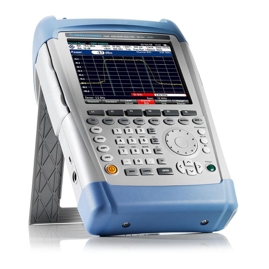
R&S FSH Putting into Operation Overview of Controls 1.2 Overview of Controls RF input (N-connector) Headphone jack BNC connectors (behind protective cap) LAN and Mini USB ports (behind protective cap) Softkey labels (on display) Softkeys Function keys Alphanumeric keypad Kensington lock DC port On/Off key Entry keys... -
Page 16: Setting Up The R&S Fsh
R&S FSH Putting into Operation Setting up the R&S FSH 1.3 Setting up the R&S FSH The R&S FSH has been designed for lab operation as well as for service and maintenance applications on-site. Depending on the environment, you can adjust the viewing angle of the display and either lay it out flat or prop it up using the support on the back of the R&S FSH. -
Page 17: Using The Ac Adapter
R&S FSH Putting into Operation Setting up the R&S FSH 1.3.1 Using the AC Adapter Connect the AC adapter (R&S HA-Z201) to the DC port on the left side of the R&S FSH (1). Make sure to fully insert the plug into the port. Depending on the system you need, firmly connect the appropriate plug included in the delivery (2) to the AC adapter. -
Page 18: Battery Operation
R&S FSH Putting into Operation Setting up the R&S FSH 1.3.2 Battery Operation The lithium ion battery has a capacity of approximately 4 Ah and allows operation of up to three hours when it is fully charged. The actual operation time depends on the current charge status, the ambient temperature and the operating mode of the R&S FSH. - Page 19 R&S FSH Putting into Operation Setting up the R&S FSH Using an external battery charger You can also use an external battery charger (R&S HA-Z203, order no. 1309.6123.00) to charge an additional replacement battery. To charge the battery externally, put the battery into the external charger and supply it with power via the AC power adapter.
-
Page 20: Battery Maintenance
R&S FSH Putting into Operation Setting up the R&S FSH 1.3.3 Battery Maintenance The R&S FSH comes with a lithium-ion battery. In general, these batteries are easy to handle. When you handle the battery, mind the things mentioned in the safety instructions and those in this chapter. -
Page 21: Transportation
R&S FSH Putting into Operation Setting up the R&S FSH 1.3.3.3 Transportation No special regulations apply for transporting the battery. The battery cells contain no metallic lithium. 1.3.3.4 End of Life The capacity of the battery decreases after it has gone through numerous charge cycles and nears its end of life. -
Page 22: Connectors On The R&S Fsh
R&S FSH Putting into Operation Connectors on the R&S FSH 1.4 Connectors on the R&S FSH The R&S FSH has several connectors. The connectors are either on the upper, left or right side. Contents ● RF Input (p. 21) ● Tracking Generator Output (p. -
Page 23: Rf Input
R&S FSH Putting into Operation Connectors on the R&S FSH 1.4.1 RF Input The RF input is located on the top of the R&S FSH. Connect a cable or DUT to the RF input with an N connector. Use a cable to connect the DUT to the R&S FSH, if necessary. -
Page 24: Tracking Generator Output
R&S FSH Putting into Operation Connectors on the R&S FSH 1.4.2 Tracking Generator Output The tracking generator output is located on the top of the R&S FSH. The tracking generator output power of the R&S FSH is 0 dBm nominal. With an integrated step attenuator, you can reduce the tracking generator output power by a maximum of 40 dB in 1 dB steps. -
Page 25: Headphone Jack
R&S FSH Putting into Operation Connectors on the R&S FSH 1.4.4 Headphone Jack The 3.5 mm connector for headphones is located on the top of the R&S FSH. The internal impedance of the connector is approximately 10 Ohm. 1.4.5 AUX Input The AUX input is located on the left side of the R&S FSH under a protective cap. -
Page 26: Bnc Connectors
R&S FSH Putting into Operation Connectors on the R&S FSH 1.4.6 BNC Connectors The BNC connectors are located on the left side of the R&S FSH behind a protective cap. You can configure both BNC connectors for various applications. The name of the connector is printed on the insides of the protective caps. -
Page 27: If Output
R&S FSH Putting into Operation Connectors on the R&S FSH 1.4.6.3 IF Output The second (lower) BNC connector can be used as an intermediate frequency output (54.4 MHz). Risk of instrument damage To avoid damage to the tracking generator output, never apply currents greater than 600 mA or voltages greater than 20 V to the BNC connectors if the BNC connectors are not configured as BIAS input ports. -
Page 28: Mini Usb And Lan Ports
R&S FSH Putting into Operation Connectors on the R&S FSH 1.4.7 Mini USB and LAN Ports The mini USB and LAN ports are located on the left side of the R&S FSH behind a protective cap. You can connect the R&S FSH to a PC via USB or LAN and transfer data in both directions. -
Page 29: Dc Port
R&S FSH Putting into Operation Connectors on the R&S FSH 1.4.9 DC Port The DC port is located on the left side of the R&S FSH. The R&S FSH is supplied with power by the AC/DC transformer power supply via the DC connector. -
Page 30: Managing Options
R&S FSH Putting into Operation Managing Options 1.5 Managing Options For special measurement tasks, you can equip the R&S FSH with various firmware options. 1.5.1 Enabling Options To enable options, you have to enter a key code. The key code is based on the unique serial number of the R&S FSH. -
Page 31: Managing Options With The R&S License Manager
R&S FSH Putting into Operation Managing Options 1.5.3 Managing Options with the R&S License Manager If you are using the R&S FSH in a local area network (LAN), you can manage firmware options with a web browser (e.g. Microsoft Internet Explorer or Mozilla Firefox). For more information on connecting the R&S FSH to a LAN see "Connecting the R&S FSH to a... - Page 32 R&S FSH Putting into Operation Managing Options In case you already have one or more R&S FSH equipped with options, you can manage the licenses of these options on the license manager web page. ► Press the button. The browser will access another part of the R&S License Manager. In this part of the license manager you can manage licenses already installed on your R&S FSH.
-
Page 33: Configuring The R&S Fsh
R&S FSH Putting into Operation Configuring the R&S FSH 1.6 Configuring the R&S FSH In the "Instrument Setup" dialog box, the R&S FSH provides various general settings that are independent of the operating mode of the R&S FSH. ► Press the SETUP key. ►... -
Page 34: Configuring The Hardware
R&S FSH Putting into Operation Configuring the R&S FSH 1.6.1 Configuring the Hardware The hardware settings contain settings that control internal and connected hardware. Using auto accessory detection If you are using any accessories while working with the R&S FSH, the R&S FSH is able to identify the connected hardware. - Page 35 R&S FSH Putting into Operation Configuring the R&S FSH The way to configure the second BNC connector is similar. ► Instead of selecting the "BNC 1" item, select the "BNC 2" item. The following applications are available: IF output DC Bias Port 1 and Port 2 (Only with models .24 and .28.) Quick Start Guide 1309.6269.12 - 09...
-
Page 36: Configuring Antennas
R&S FSH Putting into Operation Configuring the R&S FSH 1.6.2 Configuring Antennas You can use the log-periodic antenna R&S HL300 (order no. 4097.3005.02) or the active directional antenna R&S HE300 with the R&S FSH to locate potential interfering sources. For a comprehensive description of the antennas and their functionality, refer to the user manuals delivered with the product. - Page 37 R&S FSH Putting into Operation Configuring the R&S FSH Showing compass information ► In the "Instrument Setup" dialog box, select the "Show Compass Information" item. ► Press the ENTER key. The R&S FSH opens a dropdown menu to turn the display of directions on and off. ►...
- Page 38 R&S FSH Putting into Operation Configuring the R&S FSH Calibrating the antenna If you need to know specifics about the antenna, for example for service or support, you can get the necessary information in the "Antenna Service Menu" provided on the R&S FSH.
-
Page 39: Using The Gps Receiver
R&S FSH Putting into Operation Configuring the R&S FSH 1.6.3 Using the GPS Receiver The R&S FSH can locate your exact position if you equip it with the R&S HS-Z240 GPS receiver (order no. 1309.6700.02) or one of the supported antennas R&S HL300 or R&S HE300. - Page 40 R&S FSH Putting into Operation Configuring the R&S FSH When this feature is on, and a sufficient connection to GPS satellites is established, the R&S FSH displays the GPS coordinates in a blue bar below the hardware information. When the connection to a satellite is lost, the bar turns red and the GPS coordinates are shown in brackets.
-
Page 41: Configuring Date And Time
R&S FSH Putting into Operation Configuring the R&S FSH 1.6.4 Configuring Date and Time The R&S FSH has an internal clock that can apply a date and time stamp. In the "Instrument Setup" dialog box, you can set both date and time. Setting the date ►... -
Page 42: Selecting Regional Attributes
R&S FSH Putting into Operation Configuring the R&S FSH 1.6.5 Selecting Regional Attributes The regional settings allow you to select a different language, date format and length unit. Selecting the language The R&S FSH provides several languages for the user interface. ►... -
Page 43: Configuring The Display
R&S FSH Putting into Operation Configuring the R&S FSH 1.6.6 Configuring the Display The display settings configure display characteristics. The display of the R&S FSH is a TFT color LCD display. Indoors, its ideal brightness depends on the intensity of the backlight. To strike a balance between battery operating time and screen display quality, set the backlight intensity to the minimum brightness needed. -
Page 44: Configuring Audio Output
R&S FSH Putting into Operation Configuring the R&S FSH 1.6.7 Configuring Audio Output The audio settings control the audio output of the system. Setting the key click volume The key click volume sets the volume of the sound that the R&S FSH produces when you press a key or softkey. -
Page 45: Configuring Power Supply
R&S FSH Putting into Operation Configuring the R&S FSH 1.6.8 Configuring Power Supply The power settings contain settings that configure the power supply of the R&S FSH. The "Current Power Source" shows the source the R&S FSH is currently powered by. When you are using the battery to supply the R&S FSH with power, the remaining "Battery Level"... -
Page 46: Self Alignment
R&S FSH Putting into Operation Configuring the R&S FSH 1.6.9 Self Alignment The self alignment calibrates the instrument settings for vector network analysis. During the self alignment, the R&S FSH generates new factory calibration data and overwrites the old factory calibration. For the self alignment a short circuit (Short), an open circuit (Open) and a 50 Ohm match (Load) are required. -
Page 47: Resetting The R&S Fsh
R&S FSH Putting into Operation Configuring the R&S FSH 1.6.11 Resetting the R&S FSH You can either preset the R&S FSH or reset it to factory settings. Presetting the R&S FSH The PRESET key resets the R&S FSH to the default setup of the currently active operating mode. -
Page 48: Connecting The R&S Fsh To A Pc
R&S FSH Putting into Operation Connecting the R&S FSH to a PC 1.7 Connecting the R&S FSH to a PC The R&S FSH comes with the R&S FSH4View software package. This software package features several tools that allow you to document measurement results or create and edit limit lines or channel tables among other things. - Page 49 R&S FSH Putting into Operation Connecting the R&S FSH to a PC Setting an IP address and subnet mask To establish a connection, the PC and the R&S FSH have to be in the same subnet. ► Identify the subnet mask of your PC, for example in the Microsoft Windows "TCP/IP Properties".
- Page 50 R&S FSH Putting into Operation Connecting the R&S FSH to a PC Configuring the R&S FSH4View software ► Start R&S FSH4View. ► Select the "LAN" tab in the "Instrument Connect" dialog box. ► Press the "Add" button to create a new network connection. ►...
-
Page 51: Connecting The R&S Fsh In An Existing Lan
R&S FSH Putting into Operation Connecting the R&S FSH to a PC 1.7.2 Connecting the R&S FSH in an existing LAN You can either draw the R&S FSH IP address automatically from the DHCP server or manually assign a fixed address. With manual allocation, a fixed IP address and subnet mask must be assigned to the R&S FSH as described in the chapter on direct LAN connection. -
Page 52: Connecting The R&S Fsh Via Usb
R&S FSH Putting into Operation Connecting the R&S FSH to a PC 1.7.3 Connecting the R&S FSH via USB Alternatively, you can connect the R&S FSH to the PC with the USB cable that is supplied with the delivery. The Mini USB interface is located on the left side of the R&S FSH behind a protective cap. -
Page 53: Getting Started
R&S FSH Getting Started Connecting the R&S FSH to a PC 2 Getting Started This chapter provides a short overview of several basic measurements you can perform with the R&S FSH. Contents ● Using the Spectrum Analyzer (p. 52) ● Using the Network Analyzer (p. -
Page 54: Using The Spectrum Analyzer
R&S FSH Getting Started Using the Spectrum Analyzer 2.1 Using the Spectrum Analyzer This chapter provides a short overview of the first steps of the measurements you can perform with the R&S FSH. 2.1.1 Attenuating the Signal You can attenuate the signal to a suitable level either manually or automatically. In case of automatic attenuation, the level of attenuation at the RF input depends on the current reference level. -
Page 55: Using The Preamplifier
R&S FSH Getting Started Using the Spectrum Analyzer The R&S FSH provides several methods to fill in input fields: ● directly with the number keys ● with the rotary knob ● with the cursor keys While you can enter any number you want with the number keys, using the rotary knob or the cursor keys is coupled to a certain step size in most cases. -
Page 56: Measuring Cw Signals
R&S FSH Getting Started Using the Spectrum Analyzer 2.1.3 Measuring CW Signals A basic task for spectrum analyzers is to measure the level and frequency of sinewave signals. The following examples illustrate an effective way of performing these measurements. A signal generator, e.g. R&S SMBV provides the signal source. Test setup Connect the RF output of the signal generator to the RF input of the R&S FSH. - Page 57 R&S FSH Getting Started Using the Spectrum Analyzer Setting the reference level The level at the top of the measurement diagram is called the reference level. To obtain the best dynamic range from the R&S FSH, you should use its full level range. That means that the maximum level value should be at or close to the top of the measurement diagram (= reference level).
- Page 58 R&S FSH Getting Started Using the Spectrum Analyzer Measuring the frequency The trace consists of 631 measurement points (frequency points). The marker is always positioned on one of these measurement points. The R&S FSH calculates the marker frequency from the frequency of the measurement point, the center frequency and the frequency span that have been set.
-
Page 59: Measuring Harmonics
R&S FSH Getting Started Using the Spectrum Analyzer 2.1.4 Measuring Harmonics A spectrum analyzer is ideal to measure harmonic levels or harmonic ratios, because it can resolve different signals in the frequency domain. With marker functions, you can speed up measurement tasks like that. A signal generator, e.g. - Page 60 R&S FSH Getting Started Using the Spectrum Analyzer To measure the harmonic ratio, set the marker on the signal and a delta marker on the second harmonic. ► Press the MARKER key. The R&S FSH sets a marker on the trace maximum. The trace maximum corresponds to the signal.
-
Page 61: Using The Network Analyzer
R&S FSH Getting Started Using the Network Analyzer 2.2 Using the Network Analyzer R&S FSH models that feature a tracking generator can do two-port measurements like measuring the gain or attenuation of devices under test. The tracking generator generates a sine signal at the receive frequency of the R&S FSH. -
Page 62: Calibrating The R&S Fsh
R&S FSH Getting Started Using the Network Analyzer 2.2.1 Calibrating the R&S FSH Depending on the measurement mode, the R&S FSH provides several calibration methods. Basically, the procedure during calibration is the same for all calibration methods and measurement modes in that you need to connect one or more calibration standards to the port(s) of the R&S FSH. - Page 63 R&S FSH Getting Started Using the Network Analyzer Last, the R&S FSH asks you to terminate port 1 into a 50 Ω termination ("Load"). ► Connect the "Load" to port 1. ► Press the "Continue" softkey. When the calibration is finished, the R&S FSH shows the message .
-
Page 64: Measuring The Vector Reflection
R&S FSH Getting Started Using the Network Analyzer 2.2.2 Measuring the Vector Reflection To perform vector measurements you have to equip the R&S FSH with firmware application R&S FSH-K42. Reflection measurements are available for all R&S FSH models with a tracking generator and VSWR bridge. -
Page 65: Measuring Scalar Transmission
R&S FSH Getting Started Using the Network Analyzer 2.2.3 Measuring Scalar Transmission Scalar measurements are available for all R&S FSH models with a tracking generator. ► Connect the DUT between the RF input and the tracking generator output. Note that you need an R&S FSH with VSWR bridge to be able to measure the transmission in forward and reverse direction. -
Page 66: Using A Power Sensor
R&S FSH Getting Started Using a Power Sensor 2.3 Using a Power Sensor For highly accurate power measurements, you can connect one of the power sensors that are supported by the R&S FSH. The power sensors R&S FSH-Z1 and -Z18 are especially designed for use with the R&S FSH. -
Page 67: Measuring The Power With A Power Sensor
R&S FSH Getting Started Using a Power Sensor 2.3.1 Measuring the Power with a Power Sensor The power sensors R&S FSH-Z1 and R&S FSH-Z18 measure the power in the range from 10 MHz to 8 GHz and 18 GHz respectively. For more information about the characteristics of the R&S NRP power sensors, refer to their datasheets. - Page 68 R&S FSH Getting Started Using a Power Sensor If there are communication problems between the R&S FSH and the power sensor, the R&S FSH displays an error message that indicates a possible cause. For more information see the operating manual. Zeroing the power sensor To compensate internal offsets of the power meter, it needs to be compensated for before starting the measurement.
-
Page 69: Measuring Power And Return Loss
R&S FSH Getting Started Using a Power Sensor 2.3.2 Measuring Power and Return Loss With the directional power sensors R&S FSH-Z14 and R&S ZVH-Z44 you can measure the power in both directions. When you connect the directional power sensor between the source and the load, the R&S FSH measures the power from source to load (forward power) and from load to source (reverse power). - Page 70 R&S FSH Getting Started Using a Power Sensor Measuring the power ► Press the MODE key. ► Press the "Power Meter" softkey. As soon as the R&S FSH recognizes the power sensor, it shows the type of the directional power sensor that is connected in the diagram header. After a few seconds it also shows the forward power and return loss currently measured at the load.
-
Page 71: Identifying Cable Faults
R&S FSH Getting Started Identifying Cable Faults 2.4 Identifying Cable Faults The R&S FSH can perform cable measurements if it features a tracking generator and VSWR bridge. You also have to equip it with firmware option R&S FSH-K41 (DTF measurements, order no. 1304.5612.02). Test setup The test setup requires an R&S FSH, an RF cable (for example R&S FSH-Z320) and a calibration standard (for example R&S FSH-Z28 or R&S FSH-Z29). - Page 72 R&S FSH Getting Started Identifying Cable Faults Selecting the measurement port In the default state, port 1 (RF input) already is the measurement port. To select the measurement port manually, ► Press the MEAS key. ► Press the "Meas Mode" softkey. ►...
- Page 73 R&S FSH Getting Started Identifying Cable Faults You can also define new cable models on the R&S FSH or with the R&S FSH4View software and then transfer them to the R&S FSH. For more information see the operating manual. In addition to the cable model, you should also specify the length of the cable. ►...
- Page 74 R&S FSH Getting Started Identifying Cable Faults In addition to the distance to fault measurement, the R&S FSH also features a cable spectrum measurement and a reflection measurement, for example to test impedance matching. Using markers The R&S FSH has markers to read out signal levels and frequencies. Markers are always positioned on the trace.
-
Page 75: Saving And Recalling Results And Settings
R&S FSH Getting Started Saving and Recalling Results and Settings 2.5 Saving and Recalling Results and Settings The R&S FSH can store measurement results and settings in the internal memory, on a removable SD memory card or on a memory stick via the USB interface. Results and settings are always stored together, allowing them to be interpreted in context when recalled. -
Page 76: Recalling Measurement Results
R&S FSH Getting Started Saving and Recalling Results and Settings ► Specify a name for the data set in the input field of the dialog box with the number keys. In addition, moves the cursor to the left, moves it to the right and the BACK key deletes a character. -
Page 77: Index
R&S FSH Index Index AC adapter ................ 15 Headphone jack ..............23 Accessories ............... 12 IF output ................25 Accessory detection ............32 Kensington lock ..............26 Attenuation ................ 52 LAN port ................26 Audio settings ..............42 Languages ................. 40 Auto low distortion .............
Need help?
Do you have a question about the FSH4 and is the answer not in the manual?
Questions and answers