
Related Manuals for Rohde & Schwarz R&S FSV3-K106


Summary of Contents for Rohde & Schwarz R&S FSV3-K106
- Page 1 ® R&S FSV3-K106 LTE NB-IoT Measurement Application (Downlink) User Manual (;ÜêP2) 1178923202 Version 08...
- Page 2 ® ® This manual applies to the following R&S FSV3000 and R&S FSVA3000 models with firmware version 2.10 and higher: ● ® ® R&S FSV3004 (1330.5000K04) / R&S FSVA3004 (1330.5000K05) ● ® ® R&S FSV3007 (1330.5000K07) / R&S FSVA3007 (1330.5000K08) ●...
-
Page 3: Table Of Contents
® Contents R&S FSV3-K106 Contents 1 Documentation overview...............7 Getting started manual....................7 User manuals and help....................7 Service manual......................8 Instrument security procedures.................. 8 Printed safety instructions...................8 Data sheets and brochures..................8 Release notes and open-source acknowledgment (OSA).........8 Application notes, application cards, white papers, etc........... 9 Videos..........................9 2 Welcome to the LTE NB-IoT measurement application.... - Page 4 ® Contents R&S FSV3-K106 4.2.7 Frequency configuration....................45 4.2.8 Amplitude configuration....................46 4.2.9 Configuring the data capture..................50 4.2.10 Trigger configuration..................... 51 4.2.11 Parameter estimation and tracking................53 4.2.12 Configuring demodulation parameters................54 4.2.13 Automatic configuration....................56 Time alignment error measurements................ 56 Frequency sweep measurements................57 4.4.1 Channel power ACLR measurement configuration............57 4.4.2...
- Page 5 ® Contents R&S FSV3-K106 Screen layout.......................77 6.4.1 General layout.......................77 6.4.2 Layout of a single channel.................... 79 Measurement control....................86 6.5.1 Measurements......................86 6.5.2 Measurement sequences....................88 Trace data readout...................... 90 6.6.1 The TRACe[:DATA] command..................90 6.6.2 Result readout......................101 Numeric result readout.....................102 6.7.1 Result for selection......................102 6.7.2 Time alignment error....................
- Page 6 ® Contents R&S FSV3-K106 User Manual 1178.9232.02 ─ 08...
-
Page 7: Documentation Overview
® Documentation overview R&S FSV3-K106 User manuals and help 1 Documentation overview This section provides an overview of the R&S FSV/A user documentation. Unless specified otherwise, you find the documents at: www.rohde-schwarz.com/manual/FSVA3000 www.rohde-schwarz.com/manual/FSV3000 Further documents are available at: www.rohde-schwarz.com/product/FSVA3000 www.rohde-schwarz.com/product/FSV3000 1.1 Getting started manual Introduces the R&S FSV/A and describes how to set up and start working with the product. -
Page 8: Service Manual
® Documentation overview R&S FSV3-K106 Release notes and open-source acknowledgment (OSA) 1.3 Service manual Describes the performance test for checking the rated specifications, module replace- ment and repair, firmware update, troubleshooting and fault elimination, and contains mechanical drawings and spare part lists. The service manual is available for registered users on the global Rohde &... -
Page 9: Application Notes, Application Cards, White Papers, Etc
® Documentation overview R&S FSV3-K106 Videos www.rohde-schwarz.com/firmware/FSVA3000 1.8 Application notes, application cards, white papers, etc. These documents deal with special applications or background information on particu- lar topics. www.rohde-schwarz.com/application/FSV3000 www.rohde-schwarz.com/application/FSVA3000 1.9 Videos Find various videos on Rohde & Schwarz products and test and measurement topics on YouTube: https://www.youtube.com/@RohdeundSchwarz User Manual 1178.9232.02 ─... -
Page 10: Welcome To The Lte Nb-Iot Measurement Application
® Welcome to the LTE NB-IoT measurement application R&S FSV3-K106 Starting the LTE NB-IoT measurement application 2 Welcome to the LTE NB-IoT measurement application The LTE NB-IoT measurement application is a firmware application that adds function- ality to measure on NB-IoT signals according to the 3GPP standard to the R&S FSV/A. This user manual contains a description of the functionality that the application pro- vides, including remote control operation. -
Page 11: Understanding The Display Information
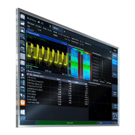
® Welcome to the LTE NB-IoT measurement application R&S FSV3-K106 Understanding the display information 2.3 Understanding the display information The following figure shows a measurement diagram during NB-IoT operation. All differ- ent information areas are labeled. They are explained in more detail in the following sections. - Page 12 ® Welcome to the LTE NB-IoT measurement application R&S FSV3-K106 Understanding the display information Frame Count Number of frames that have been captured Subframe Subframe considered in the signal analysis In addition, the channel bar displays information on instrument settings that affect the measurement results even though this is not immediately apparent from the display of the measured values (for example trigger settings).
-
Page 13: Measurements And Result Displays
® Measurements and result displays R&S FSV3-K106 Selecting measurements 3 Measurements and result displays The LTE NB-IoT measurement application measures and analyzes various aspects of an NB-IoT signal. It features several measurements and result displays. Measurements represent differ- ent ways of processing the captured data during the digital signal processing. Result displays are different representations of the measurement results. -
Page 14: Selecting Result Displays
® Measurements and result displays R&S FSV3-K106 Selecting result displays Time alignment error Time alignment error (TAE) measurements record, process and demodulate the sig- nal's I/Q data. The result displays available for TAE measurements indicate how well the antennas in a multi-antenna system are aligned. For TAE measurements, you can combine the result displays in any way. -
Page 15: Performing Measurements
® Measurements and result displays R&S FSV3-K106 I/Q measurements From that predefined state, add and remove result displays as you like from the Smart- Grid menu. Remote command: on page 79 LAYout:ADD[:WINDow]? 3.3 Performing measurements By default, the application measures the signal continuously. In "Continuous Sweep" mode, the R&S FSV/A captures and analyzes the data again and again. -
Page 16: Capture Buffer
® Measurements and result displays R&S FSV3-K106 I/Q measurements EVM vs Symbol x Carrier....................25 Power vs Symbol x Carrier....................25 Allocation ID vs Symbol x Carrier..................26 Result Summary......................26 Marker Table......................... 28 Capture Buffer The "Capture Buffer" shows the complete range of captured data for the last data cap- ture. -
Page 17: Evm Vs Carrier
® Measurements and result displays R&S FSV3-K106 I/Q measurements Figure 3-2: Capture buffer after a zoom has been applied Remote command: Selection: LAY:ADD ? '1',LEFT,CBUF Query (y-axis): TRACe:DATA? Query (x-axis): on page 100 TRACe<n>[:DATA]:X? Subframe start offset: on page 107 FETCh[:CC<cc>]:SUMMary:TFRame? EVM vs Carrier The "EVM vs Carrier"... -
Page 18: Evm Vs Symbol
® Measurements and result displays R&S FSV3-K106 I/Q measurements Remote command: Selection LAY:ADD ? '1',LEFT,EVCA Query (y-axis): TRACe:DATA? Query (x-axis): on page 100 TRACe<n>[:DATA]:X? EVM vs Symbol The "EVM vs Symbol" result display shows the error vector magnitude (EVM) of the OFDM symbols. -
Page 19: Evm Vs Subframe
® Measurements and result displays R&S FSV3-K106 I/Q measurements EVM vs Subframe The "EVM vs Subframe" result display shows the Error Vector Magnitude (EVM) for each subframe. You can use it as a debugging technique to identify a subframe whose EVM is too high. -
Page 20: Power Spectrum
® Measurements and result displays R&S FSV3-K106 I/Q measurements Remote command: Selection: LAY:ADD ? '1',LEFT,FEVS Query (y-axis): TRACe:DATA? Query (x-axis): on page 100 TRACe<n>[:DATA]:X? Power Spectrum The "Power Spectrum" shows the power density of the complete capture buffer in dBm/Hz. The displayed bandwidth is always 7.68 MHz. -
Page 21: Group Delay
® Measurements and result displays R&S FSV3-K106 I/Q measurements Group Delay This "Group Delay" shows the group delay of each subcarrier. The measurement is evaluated over the currently selected slot in the currently selected subframe. The currently selected subframe depends on your selection. The x-axis represents the frequency. -
Page 22: Ccdf
® Measurements and result displays R&S FSV3-K106 I/Q measurements In the default state, the result display evaluates the full range of the measured input data. Each color represents a modulation type. ● : BPSK ● : RBPSK ● : MIXTURE ●... -
Page 23: Allocation Summary
® R&S FSV3-K106 Measurements and result displays I/Q measurements Mean Mean power Peak Peak power Crest Crest factor (peak power – mean power) 10 % 10 % probability that the level exceeds mean power + [x] dB 1 % probability that the level exceeds mean power + [x] dB 0.1 % 0.1 % probability that the level exceeds mean power + [x] dB 0.01 %... -
Page 24: Bitstream
® R&S FSV3-K106 Measurements and result displays I/Q measurements Remote command: Selection: LAY:ADD ? '1',LEFT,ASUM Query: TRACe:DATA? Bitstream The "Bitstream" shows the demodulated data stream for the data allocations. At the end of the table is a summary of the bitstream for certain configurations. ●... - Page 25 ® Measurements and result displays R&S FSV3-K106 I/Q measurements Indicates the position of the table row's first bit or symbol within the complete stream. ● Bit Stream The actual bit stream. Remote command: Selection: LAY:ADD ? '1',LEFT,BSTR EVM vs Symbol x Carrier The "EVM vs Symbol x Carrier"...
- Page 26 ® Measurements and result displays R&S FSV3-K106 I/Q measurements Allocation ID vs Symbol x Carrier The "Allocation ID vs Symbol x Carrier" result display is a graphical representation of the structure of the analyzed frame. It shows the allocation type of each subcarrier in each symbol of the received signal.
- Page 27 ® Measurements and result displays R&S FSV3-K106 I/Q measurements In addition to the red font, the application also puts a red star ( ) in front of failed results. By default, all EVM results are in %. To view the EVM results in dB, change the Unit.
- Page 28 ® Measurements and result displays R&S FSV3-K106 I/Q measurements NB-IoT Power Shows the power of all resource elements used by NB-IoT. on page 106 FETCh[:CC<cc>]:SUMMary:NBPower[:AVERage]? Crest Factor Shows the peak-to-average power ratio of captured signal. on page 103 FETCh[:CC<cc>]:SUMMary:CRESt[:AVERage]? Marker Table Displays a table with the current marker values for the active markers.
-
Page 29: Time Alignment Error
® Measurements and result displays R&S FSV3-K106 Time alignment error 3.5 Time alignment error Access: "Overview" > "Select Measurement" > "Time Alignment" The time alignment error measurement captures and analyzes new I/Q data when you select it. The time alignment error measurement only works under the following conditions: ●... -
Page 30: Frequency Sweep Measurements
® Measurements and result displays R&S FSV3-K106 Frequency sweep measurements You can select the reference antenna from the dropdown menu in the result display. You can also select the reference antenna in the MIMO Setup - if you change them in one place, they are also changed in the other. -
Page 31: Result Display Selection: Layout:add[:Window]? On Page 79 Adjacent Channel Leakage Ratio (Aclr)
® Measurements and result displays R&S FSV3-K106 Frequency sweep measurements Remote command: Measurement selection: on page 113 CONFigure[:LTE]:MEASurement Result display selection: on page 79 LAYout:ADD[:WINDow]? Adjacent Channel Leakage Ratio (ACLR)..............31 └ Result diagram....................31 └ Result summary....................31 Spectrum Emission Mask (SEM).................. -
Page 32: Spectrum Emission Mask (Sem)
® Measurements and result displays R&S FSV3-K106 Frequency sweep measurements ● Channel Shows the channel type (Tx, adjacent or alternate channel). ● Bandwidth Shows the channel bandwidth. ● Offset Shows the channel spacing. ● Power Shows the power of the Tx channel. ●... -
Page 33: Marker Peak List
® Measurements and result displays R&S FSV3-K106 Frequency sweep measurements Shows the absolute frequency whose power measurement being closest to the limit line for the corresponding frequency segment. ● Power Abs Shows the absolute measured power of the frequency whose power is closest to the limit. -
Page 34: Configuration
® Configuration R&S FSV3-K106 Configuration overview 4 Configuration LTE NB-IoT measurements require a special application on the R&S FSV/A, which you can select by adding a new measurement channel or replacing an existing one. When you start the LTE NB-IoT application, the R&S FSV/A starts to measure the input signal with the default configuration or the configuration of the last measurement (if you haven't performed a preset since then). - Page 35 ® Configuration R&S FSV3-K106 Configuration overview In addition to the main measurement settings, the "Overview" provides quick access to the main settings dialog boxes. The individual configuration steps are displayed in the order of the data flow. Thus, you can easily configure an entire measurement channel from input over processing to output and analysis by stepping through the dialog boxes as indicated in the "Overview".
-
Page 36: I/Q Measurements
® Configuration R&S FSV3-K106 I/Q measurements Note: Do not confuse the "Preset Channel" button with the [Preset] key, which restores the entire instrument to its default values and thus closes all channels on the R&S FSV/A (except for the default channel)! Remote command: on page 114 SYSTem:PRESet:CHANnel[:EXEC]... - Page 37 ® Configuration R&S FSV3-K106 I/Q measurements The contents of the "Signal Description" dialog box depend on the deployment you have selected. The remote commands required to configure the physical signal characteristics are described in "Physical settings" on page 115. Selecting the NB-IoT mode...................
- Page 38 ® Configuration R&S FSV3-K106 I/Q measurements The application supports the following deployments. ● "Stand Alone" The NB-IoT signal uses a dedicated spectrum outside of an LTE band, for example a frequency band currently used by GSM. With a carrier bandwidth of 200 kHz in GSM, there is enough room for an NB-IoT carrier (180 kHz), including a guard interval of 10 kHz on both sides of the carrier.
- Page 39 ® Configuration R&S FSV3-K106 I/Q measurements Note that the 1.4 MHz bandwidth is not supported for in band transmission of NB- IoT signals. ● "E-UTRA CRS Sequence Info" Cell-specific reference signal sequence. The sequence defines the assignment of resources between LTE and NB-IoT. These sequences are defined in 3GPP 36.213, chapter 16.8.
- Page 40 ® Configuration R&S FSV3-K106 I/Q measurements In addition, the application shows various physical properties of the NB-IoT signal. ● "NB-IoT Channel Bandwidth", which is currently always 200 kHz. ● "NB-IoT Center Frequency", which is calculated from the E-UTRA channel charac- teristics.
-
Page 41: Test Scenarios
® Configuration R&S FSV3-K106 I/Q measurements 4.2.2 Test scenarios Access: "Overview" > "Signal Description" > "Test Models" Test scenarios are descriptions of specific NB-IoT signals for standardized testing of DUTs. These test scenarios are stored in .allocation files. You can select, manage and create test scenarios in the "Test Models"... -
Page 42: Npdsch Settings
® Configuration R&S FSV3-K106 I/Q measurements Remote command: on page 122 CONFigure[:LTE]:DL[:CC<cc>]:MIMO:CONFig Tx Antenna Selection The "Tx Antenna Selection" selects the antenna(s) you want to analyze. The number of menu items depends on the number of antennas in the system. Each antenna corresponds to a cell-specific reference signal. -
Page 43: Configuring The Control Channel
® Configuration R&S FSV3-K106 I/Q measurements This information about the NPDSCH is required to distinguish between NPDSCH and NPDCCH information, which in turn is required to calculate bit error information in the bitstream result display. Remote command: State: on page 123 CONFigure[:LTE]:DL:NPDSch:DMODulation Subframes: on page 123... - Page 44 ® Configuration R&S FSV3-K106 I/Q measurements YIG-Preselector Enables or disables the YIG-preselector. This setting requires an additional option R&S FSV3-B11 on the R&S FSV/A. An internal YIG-preselector at the input of the R&S FSV/A ensures that image frequen- cies are rejected. However, image rejection is only possible for a restricted bandwidth. To use the maximum bandwidth for signal analysis, you can disable the YIG-preselec- tor at the input of the R&S FSV/A, which can lead to image-frequency display.
-
Page 45: Frequency Configuration
® Configuration R&S FSV3-K106 I/Q measurements Note: Even when the file input is disabled, the input file remains selected and can be enabled again quickly by changing the state. Remote command: on page 126 INPut<ip>:SELect Select I/Q data file Opens a file selection dialog box to select an input file that contains I/Q data. The I/Q data must have a specific format (.iq.tar) as described in R&S FSV/A I/Q Analyzer and I/Q Input user manual. -
Page 46: Amplitude Configuration
® Configuration R&S FSV3-K106 I/Q measurements Signal Frequency......................46 └ Center Frequency................... 46 └ Frequency Stepsize..................46 Signal Frequency For measurements with an RF input source, you have to match the center frequency of the analyzer to the frequency of the signal. Center Frequency ←... - Page 47 ® Configuration R&S FSV3-K106 I/Q measurements The remote commands required to configure the amplitude are described in Chap- ter 6.8.2.4, "Amplitude configuration", on page 128. Reference Level......................47 └ Auto Level....................... 47 └ Reference Level Offset................... 48 Attenuating the Signal....................48 └...
- Page 48 ® Configuration R&S FSV3-K106 I/Q measurements Reference Level Offset ← Reference Level The reference level offset is an arithmetic level offset. A level offset is useful if the sig- nal is attenuated or amplified before it is fed into the analyzer. All displayed power level results are shifted by this value.
- Page 49 ® Configuration R&S FSV3-K106 I/Q measurements Note that the frequency range must not exceed the specification of the electronic attenuator for it to work. The application shows the attenuation level (mechanical and electronic) in the channel bar. Remote command: Electronic attenuation: on page 133 INPut<ip>:EATT<ant>:STATe Electronic attenuation:...
-
Page 50: Configuring The Data Capture
® Configuration R&S FSV3-K106 I/Q measurements However, some specifications require DC coupling. In this case, you must protect the instrument from damaging DC input voltages manually. For details, refer to the data sheet. Remote command: on page 130 INPut<ip>:COUPling Impedance For some measurements, the reference impedance for the measured levels of the R&S FSV/A can be set to 50 Ω... -
Page 51: Trigger Configuration
® Configuration R&S FSV3-K106 I/Q measurements Swap I/Q Swaps the real (I branch) and the imaginary (Q branch) parts of the signal. Remote command: on page 134 [SENSe:]SWAPiq Overall Frame Count The "Overall Frame Count" turns the manual selection of the number of frames to cap- ture (and analyze) on and off. - Page 52 ® Configuration R&S FSV3-K106 I/Q measurements While the application runs freely and analyzes all signal data in its default state, no matter if the signal contains information or not, a trigger initiates a measurement only under certain circumstances (the trigger event). Except for the available trigger sources, the functionality is the same as that of the R&S FSV/A base system.
-
Page 53: Parameter Estimation And Tracking
® Configuration R&S FSV3-K106 I/Q measurements ● The trigger "Offset" is the time that must pass between the trigger event and the start of the measurement. This can be a negative value (a pretrigger). ● The trigger "Drop-out Time" defines the time the input signal must stay below the trigger level before triggering again. -
Page 54: Configuring Demodulation Parameters
® Configuration R&S FSV3-K106 I/Q measurements Boosting estimation is always active. Remote command: on page 141 [SENSe:][LTE:]DL:DEMod:BESTimation Channel Estimation Selects the method of channel estimation. ● EVM 3GPP Definition Channel estimation according to 3GPP TS 36.141. This method is based on aver- aging in frequency direction and linear interpolation. - Page 55 ® Configuration R&S FSV3-K106 I/Q measurements The remote commands required to configure the demodulation are described in Chap- ter 6.8.2.7, "Demodulation", on page 140. Multicarrier Filter......................55 Scrambling of Coded Bits....................55 EVM Calculation Method....................55 NPDSCH Reference Data.....................55 Compensate Crosstalk....................56 Multicarrier Filter Turns the suppression of interference of neighboring carriers for tests on multiradio base stations on and off (e.g.
-
Page 56: Automatic Configuration
® Configuration R&S FSV3-K106 Time alignment error measurements "All 0" Assumes the NPDSCH to be all 0's, according to test model defini- tions. Remote command: on page 141 [SENSe:][LTE:]DL:DEMod:PRData Compensate Crosstalk Turns compensation of crosstalk produced by one of the components in the test setup on and off. -
Page 57: Frequency Sweep Measurements
® Configuration R&S FSV3-K106 Frequency sweep measurements ● Chapter 4.2.1, "Defining signal characteristics", on page 36 ● Chapter 4.2.5, "Configuring the control channel", on page 43 ● Chapter 4.2.6, "Input source configuration", on page 43 ● Chapter 4.2.7, "Frequency configuration", on page 45 ●... -
Page 58: Sem Measurement Configuration
® Configuration R&S FSV3-K106 Frequency sweep measurements ● "Channel Bandwidth": The channel bandwidth for the stand-alone deployment is a fix value of 200 kHz. ● "Adjacent Channels": Selects the adjacent channel configuration for the "Stand Alone" deployment as specified by 3GPP 36.104 chapter 6.6.2. 4.4.2 SEM measurement configuration Access: "Overview"... - Page 59 ® Configuration R&S FSV3-K106 Frequency sweep measurements You can define the channel power either manually or automatically. For automatic detection, the R&S FSV/A measures the power of the transmission channel. Remote command: State: on page 145 [SENSe:]POWer:SEM:CHBS:AMPower:AUTO Power: on page 145 [SENSe:]POWer:SEM:CHBS:AMPower Power NB-IoT Carrier Defines the power of the NB-IoT carrier.
-
Page 60: Analysis
® Analysis R&S FSV3-K106 General analysis tools 5 Analysis The R&S FSV/A provides various tools to analyze the measurement results. ● General analysis tools.....................60 ● Analysis tools for I/Q measurements..............63 ● Analysis tools for frequency sweep measurements..........67 5.1 General analysis tools The general analysis tools are tools available for all measurements. -
Page 61: Microservice Export
® Analysis R&S FSV3-K106 General analysis tools 2. Select "Export" > "I/Q Export". 3. Define a file name and location for the I/Q data. The file type is iq.tar. 4. Later on, you can import the I/Q data using the I/Q file input source. -
Page 62: Zoom
® Analysis R&S FSV3-K106 General analysis tools You can restore the original scale anytime with the "Restore Scale" button. Remote command: DISPlay[:WINDow<n>][:SUBWindow<w>]:TRACe<t>:Y[:SCALe]:MAXimum on page 152 DISPlay[:WINDow<n>][:SUBWindow<w>]:TRACe<t>:Y[:SCALe]:MINimum on page 152 Automatic scaling of the y-axis Usually, the best way to view the results is if they fit ideally in the diagram area and display the complete trace. -
Page 63: Analysis Tools For I/Q Measurements
® Analysis R&S FSV3-K106 Analysis tools for I/Q measurements For I/Q measurement, the R&S FSV/A supports up to four markers, for frequency sweep measurements there are more. Markers give either absolute values (normal markers) or values relative to the first marker (deltamarkers). If a result display has more than one trace, for example the "EVM vs Symbol"... -
Page 64: Evaluation Range
® Analysis R&S FSV3-K106 Analysis tools for I/Q measurements Add and remove columns as required. 5.2.2 Evaluation range Access: "Overview" > "Evaluation Range" The evaluation range defines the signal parts that are considered during signal analy- sis. Subframe Selection.......................64 Evaluation range for the constellation diagram............. - Page 65 ® Analysis R&S FSV3-K106 Analysis tools for I/Q measurements You can apply the filter to the following result displays. ● Result Summary ● EVM vs Carrier / EVM vs Symbol / EVM vs Symbol X Carrier ● Group Delay ● Power vs Symbol X Carrier ●...
-
Page 66: Result Settings
® Analysis R&S FSV3-K106 Analysis tools for I/Q measurements 5.2.3 Result settings Access: "Overview" > "Analysis" > "Result Settings" Result settings define the way certain measurement results are displayed. Unit........................66 Bit Stream Format......................66 Carrier Axes........................66 Marker Coupling......................67 EVM Unit The "EVM Unit"... -
Page 67: Analysis Tools For Frequency Sweep Measurements
® Analysis R&S FSV3-K106 Analysis tools for frequency sweep measurements X-axis shows the results in terms of the subcarrier number. Remote command: on page 153 UNIT:CAXes Marker Coupling Couples or decouples markers that are active in multiple result displays. When you turn on this feature, the application moves the marker to its new position in all active result displays. -
Page 68: Remote Control
® Remote control R&S FSV3-K106 Common suffixes 6 Remote control The following remote control commands are required to configure and perform LTE NB-IoT measurements in a remote environment. The R&S FSV/A must already be set up for remote operation in a network as described in the base unit manual. Universal functionality Note that basic tasks that are also performed in the base unit in the same way are not described here. -
Page 69: Introduction
® Remote control R&S FSV3-K106 Introduction Table 6-1: Common suffixes used in remote commands in the LTE NB-IoT measurement application Suffix Value range Description <m> 1..4 Marker <n> 1..16 Window (in the currently selected channel) <t> 1..6 Trace <li> 1 to 8 Limit line <ant>... -
Page 70: Long And Short Form
® Remote control R&S FSV3-K106 Introduction If not specified otherwise, commands can be used both for setting and for querying parameters. If a command can be used for setting or querying only, or if it initiates an event, the usage is stated explicitly. ●... -
Page 71: Optional Keywords
® Remote control R&S FSV3-K106 Introduction If you do not quote a suffix for keywords that support one, a 1 is assumed. Example: DISPlay[:WINDow<1...4>]:ZOOM:STATe enables the zoom in a particular mea- surement window, selected by the suffix at WINDow. DISPlay:WINDow4:ZOOM:STATe ON refers to window 4. 6.2.4 Optional keywords Some keywords are optional and are only part of the syntax because of SCPI compli- ance. - Page 72 ® Remote control R&S FSV3-K106 Introduction Example: LAYout:ADD:WINDow Spectrum,LEFT,MTABle Parameters can have different forms of values. ● Numeric values....................... 72 ● Boolean........................73 ● Character data......................73 ● Character strings.....................73 ● Block data....................... 73 6.2.6.1 Numeric values Numeric values can be entered in any form, i.e. with sign, decimal point or exponent. For physical quantities, you can also add the unit.
- Page 73 ® Remote control R&S FSV3-K106 Introduction ● INF/NINF Infinity or negative infinity. Represents the numeric values 9.9E37 or -9.9E37. ● Not a number. Represents the numeric value 9.91E37. NAN is returned if errors occur. 6.2.6.2 Boolean Boolean parameters represent two states. The "on" state (logically true) is represented by "ON"...
-
Page 74: Nb-Iot Application Selection
® Remote control R&S FSV3-K106 NB-IoT application selection The ASCII character # introduces the data block. The next number indicates how many of the following digits describe the length of the data block. The data bytes follow. Dur- ing the transmission of these data bytes, all end or other control signs are ignored until all bytes are transmitted. - Page 75 ® Remote control R&S FSV3-K106 NB-IoT application selection INSTrument:CREate:REPLace <ChannelName1>,<ChannelType>,<ChannelName2> Replaces a channel with another one. Setting parameters: <ChannelName1> String containing the name of the channel you want to replace. <ChannelType> Channel type of the new channel. For a list of available channel types, see INSTrument:LIST? on page 75.
- Page 76 ® Remote control R&S FSV3-K106 NB-IoT application selection Table 6-2: Available channel types and default channel names Application <ChannelType> Parameter Default Channel Name*) Spectrum SANALYZER Spectrum 5G NR (R&S FSV3-K144) NR5G 5G NR 3GPP FDD BTS BWCD 3G FDD BTS (R&S FSV3-K72) 3GPP FDD UE MWCD...
-
Page 77: Screen Layout
® Remote control R&S FSV3-K106 Screen layout Example: INST:REN 'IQAnalyzer2','IQAnalyzer3' Renames the channel with the name 'IQAnalyzer2' to 'IQAna- lyzer3'. Usage: Setting only INSTrument[:SELect] <ChannelType> Selects a new measurement channel with the defined channel type. Parameters: <ChannelType> NIOT LTE NB-IoT measurement channel Example: //Select LTE NB-IoT application INST NIOT... - Page 78 ® Remote control R&S FSV3-K106 Screen layout DISPlay[:WINDow<n>]:SIZE <Size> Maximizes the size of the selected result display window temporarily. To change the size of several windows on the screen permanently, use the LAY:SPL command (see on page 83). LAYout:SPLitter Suffix: <n>...
-
Page 79: Layout Of A Single Channel
® Remote control R&S FSV3-K106 Screen layout <tab> 1..n Example: //Select a tab DISP:WIND2:TAB2:SEL 6.4.2 Layout of a single channel The following commands are required to change the evaluation type and rearrange the screen layout for a measurement channel as you do using the SmartGrid in manual operation. - Page 80 ® Remote control R&S FSV3-K106 Screen layout Return values: <NewWindowName> When adding a new window, the command returns its name (by default the same as its number) as a result. Example: LAY:ADD? '1',LEFT,MTAB Result: Adds a new window named '2' with a marker table to the left of window 1.
-
Page 81: Layout:catalog[:Window]
® Remote control R&S FSV3-K106 Screen layout Parameter value Window type FEVS "Frequency Error vs. Symbol" GDEL "Group Delay" MTAB "Marker Table" PSPE "Power Spectrum" PVSC "Power vs. Symbol X Carrier" RSUM "Result Summary" Time alignment error CBUF "Capture Buffer" MTAB "Marker Table"... -
Page 82: Layout:identify[:Window]
® Remote control R&S FSV3-K106 Screen layout LAYout:IDENtify[:WINDow]? <WindowName> Queries the index of a particular display window in the active channel. Note: to query the name of a particular window, use the LAYout:WINDow<n>: query. IDENtify? Query parameters: <WindowName> String containing the name of a window. Return values: <WindowIndex>... - Page 83 ® Remote control R&S FSV3-K106 Screen layout LAYout:SPLitter <Index1>, <Index2>, <Position> Changes the position of a splitter and thus controls the size of the windows on each side of the splitter. Note that windows must have a certain minimum size. If the position you define con- flicts with the minimum size of any of the affected windows, the command does not work, but does not return an error.
- Page 84 ® Remote control R&S FSV3-K106 Screen layout Example: LAY:SPL 1,3,50 Moves the splitter between window 1 ('Frequency Sweep') and 3 ('"Marker Table"') to the center (50%) of the screen, i.e. in the figure above, to the left. Example: LAY:SPL 1,4,70 Moves the splitter between window 1 ('Frequency Sweep') and 3 ('"Marker Peak List"') towards the top (70%) of the screen.
-
Page 85: Layout:window
® Remote control R&S FSV3-K106 Screen layout Note: to query the index of a particular window, use the LAYout:IDENtify[: command. WINDow]? Suffix: <n> Window Return values: <WindowName> String containing the name of a window. In the default state, the name of the window is its index. Example: LAY:WIND2:IDEN? Queries the name of the result display in window 2.:Replace -
Page 86: Measurement Control
® Remote control R&S FSV3-K106 Measurement control LAYout:WINDow<n>:TYPE <WindowType> Queries or defines the window type of the window specified by the index <n>. The win- dow type determines which results are displayed. For a list of possible window types, on page 79. LAYout:ADD[:WINDow]? Note that this command is not available in all applications and measurements. - Page 87 ® Remote control R&S FSV3-K106 Measurement control Example: ABOR;:INIT:IMM Aborts the current measurement and immediately starts a new one. Example: ABOR;*WAI INIT:IMM Aborts the current measurement and starts a new one once abortion has been completed. Usage: Event INITiate<n>:CONTinuous <State> Controls the measurement mode for an individual channel.
-
Page 88: Measurement Sequences
® Remote control R&S FSV3-K106 Measurement control [SENSe:]SYNC[:CC<cc>][:STATe]? Queries the current synchronization state. Suffix: <cc> irrelevant Return values: <State> The string contains the following information: A zero represents a failure and a one represents a successful synchronization. Example: //Query synchronization state SYNC:STAT? Would return, e.g. - Page 89 ® Remote control R&S FSV3-K106 Measurement control INITiate:SEQuencer:MODE <Mode> Defines the capture mode for the entire measurement sequence and all measurement groups and channels it contains. Note: To synchronize to the end of a measurement sequence using *OPC, *OPC? or *WAI, use SINGle Sequencer mode.
-
Page 90: Trace Data Readout
® Remote control R&S FSV3-K106 Trace data readout 6.6 Trace data readout ● The TRACe[:DATA] command................90 ● Result readout.......................101 6.6.1 The TRACe[:DATA] command This chapter contains information on the TRACe:DATA command and a detailed description of the characteristics of that command. The TRACe:DATA command queries the trace data or results of the currently active measurement or result display. -
Page 91: Adjacent Channel Leakage Ratio
® Remote control R&S FSV3-K106 Trace data readout ● EVM vs symbol....................... 96 ● EVM vs symbol x carrier..................96 ● Frequency error vs symbol..................97 ● Power spectrum...................... 97 ● Power vs symbol x carrier..................97 ● Spectrum emission mask..................98 ●... - Page 92 ® Remote control R&S FSV3-K106 Trace data readout The return values have the following characteristics. ● The <allocation ID is encoded. For the code assignment, see Chapter 6.6.1.19, "Return value codes", on page 98. ● The unit for <relative power> is always dB. ●...
-
Page 93: Bit Stream
® Remote control R&S FSV3-K106 Trace data readout (...) //ALL for all subframes -2,-2,,,,,2.13196434228374E-06 6.6.1.4 Bit stream For the bitstream result display, the number of return values depends on the parame- ter. ● TRACE:DATA TRACE1 Returns several values and the bitstream for each line of the table. <subframe>, <allocation ID>, <codeword>, <modulation>, <# of symbols/bits>, <hexadecimal/binary numbers>,... -
Page 94: Ccdf
® Remote control R&S FSV3-K106 Trace data readout The following parameters are supported. ● TRAC:DATA TRACE1 Note that the command returns positive peak values only. 6.6.1.6 CCDF For the CCDF result display, the type of return values depends on the parameter. ●... -
Page 95: Group Delay
® Remote control R&S FSV3-K106 Trace data readout Returns the average power over all subframes. ● TRAC:DATA TRACE2 Returns the minimum power found over all subframes. If you are analyzing a partic- ular subframe, it returns nothing. ● TRAC:DATA TRACE3 Returns the maximum power found over all subframes. -
Page 96: Evm Vs Carrier
® Remote control R&S FSV3-K106 Trace data readout 6.6.1.11 EVM vs carrier For the EVM vs carrier result display, the command returns one value for each subcar- rier that has been analyzed. <EVM>, ... The unit depends on UNIT:EVM. The following parameters are supported. ●... -
Page 97: Frequency Error Vs Symbol
® Remote control R&S FSV3-K106 Trace data readout <EVM[Symbol(1),Carrier(1)]>, ..., <EVM[Symbol(1),Carrier(n)]>, <EVM[Symbol(n),Carrier(1)]>, ..., <EVM[Symbol(n),Carrier(n)]>, The unit depends on UNIT:EVM. Resource elements that are unused return NAN. The following parameters are supported. ● TRAC:DATA TRACE1 6.6.1.15 Frequency error vs symbol For the frequency error vs symbol result display, the command returns one value for each OFDM symbol that has been analyzed. -
Page 98: Spectrum Emission Mask
® Remote control R&S FSV3-K106 Trace data readout The following parameters are supported. ● TRAC:DATA TRACE1 6.6.1.18 Spectrum emission mask For the SEM measurement, the number and type of returns values depend on the parameter. ● TRAC:DATA TRACE1 Returns one value for each trace point. <absolute power>, ... - Page 99 ® Remote control R&S FSV3-K106 Trace data readout ● 2 = alternate channel <codeword> Represents the codeword of an allocation. The range is {0...6}. ● 0 = 1/1 ● 1 = 1/2 ● 2 = 2/2 ● 3 = 1/4 ●...
- Page 100 ® Remote control R&S FSV3-K106 Trace data readout Query parameters: <TraceNumber> TRACE1 | TRACE2 | TRACE3 Queries the trace data of the corresponding trace. LIST Queries the results for the SEM measurement. Return values: <TraceData> For more information about the type of return values in the differ- ent result displays, see Chapter 6.6.1, "The TRACe[:DATA] com- mand",...
-
Page 101: Result Readout
® Remote control R&S FSV3-K106 Trace data readout 6.6.2 Result readout ......101 CALCulate<n>:MARKer<m>:FUNCtion:POWer<sb>:RESult[:CURRent]? CALCulate<n>:MARKer<m>:FUNCtion:POWer<sb>:RESult[:CURRent]? [<Measurement>] Queries the results of the ACLR measurement or the total signal power level of the SEM measurement. To get a valid result, you have to perform a complete measurement with synchroniza- tion to the end of the measurement before reading out the result. -
Page 102: Numeric Result Readout
® Remote control R&S FSV3-K106 Numeric result readout Results for the ACLR measurements: Relative power levels of the ACLR channels. The number of return values depends on the number of transmission and adja- cent channels. The order of return values is: •... - Page 103 ® Remote control R&S FSV3-K106 Numeric result readout ............. 104 FETCh[:CC<cc>]:SUMMary:FERRor[:AVERage]? ..............105 FETCh[:CC<cc>]:SUMMary:OSTP:MAXimum? ..............105 FETCh[:CC<cc>]:SUMMary:OSTP:MINimum? ..............105 FETCh[:CC<cc>]:SUMMary:OSTP[:AVERage]? ............... 105 FETCh[:CC<cc>]:SUMMary:POWer:MAXimum? ..............105 FETCh[:CC<cc>]:SUMMary:POWer:MINimum? .............. 105 FETCh[:CC<cc>]:SUMMary:POWer[:AVERage]? ..............106 FETCh[:CC<cc>]:SUMMary:NBP:MAXimum? ..............106 FETCh[:CC<cc>]:SUMMary:NBP:MINimum? ............106 FETCh[:CC<cc>]:SUMMary:NBPower[:AVERage]? ..............106 FETCh[:CC<cc>]:SUMMary:RSSI:MAXimum? ..............
- Page 104 ® Remote control R&S FSV3-K106 Numeric result readout Example: //Query EVM FETC:SUMM:EVM? Usage: Query only FETCh[:CC<cc>]:SUMMary:EVM:PCHannel:MAXimum? FETCh[:CC<cc>]:SUMMary:EVM:PCHannel:MINimum? FETCh[:CC<cc>]:SUMMary:EVM:PCHannel[:AVERage]? Queries the EVM of all physical channel resource elements. Suffix: <cc> Component Carrier Return values: <EVM> <numeric value> EVM in % or dB, depending on the unit you have set. Example: //Query EVM FETC:SUMM:EVM:PCH?
- Page 105 ® Remote control R&S FSV3-K106 Numeric result readout Return values: <FrequencyError> <numeric value> Minimum, maximum or average frequency error, depending on the last command syntax element. Default unit: Hz Example: //Query average frequency error FETC:SUMM:FERR? Usage: Query only FETCh[:CC<cc>]:SUMMary:OSTP:MAXimum? FETCh[:CC<cc>]:SUMMary:OSTP:MINimum? FETCh[:CC<cc>]:SUMMary:OSTP[:AVERage]? Queries the OSTP.
- Page 106 ® Remote control R&S FSV3-K106 Numeric result readout FETCh[:CC<cc>]:SUMMary:NBP:MAXimum? FETCh[:CC<cc>]:SUMMary:NBP:MINimum? FETCh[:CC<cc>]:SUMMary:NBPower[:AVERage]? Queries the NB-IoT power. Suffix: <cc> irrelevant Return values: <Power> <numeric value> Minimum, maximum or average power, depending on the last command syntax element. Default unit: dBm Example: //Query NB-IoT power FETC:SUMM:NBP? Usage: Query only...
-
Page 107: Time Alignment Error
® Remote control R&S FSV3-K106 Numeric result readout Example: //Query RSTP FETC:SUMM:RSTP? Usage: Query only FETCh[:CC<cc>]:SUMMary:SERRor:MAXimum? FETCh[:CC<cc>]:SUMMary:SERRor:MINimum? FETCh[:CC<cc>]:SUMMary:SERRor[:AVERage]? Queries the sampling error. Suffix: <cc> Component Carrier Return values: <SamplingError> <numeric value> Minimum, maximum or average sampling error, depending on the last command syntax element. Default unit: ppm Example: //Query average sampling error... -
Page 108: Marker Table
® Remote control R&S FSV3-K106 Numeric result readout FETCh:FERRor[:CC<cc>][:AVERage]? Queries the carrier frequency error. Suffix: <cc> Component Carrier Return values: <FrequencyError> <numeric value> Average, minimum or maximum frequency error, depending on the command syntax. Default unit: Hz Example: //Query frequency error. FETC:FERR? Usage: Query only... - Page 109 ® Remote control R&S FSV3-K106 Numeric result readout If necessary, the command activates the delta marker and positions a reference marker to the peak power. Suffix: <n> Window <m> Marker Parameters: <Position> Numeric value that defines the marker position on the x-axis. Range: The value range and unit depend on the measure- ment and scale of the x-axis.
- Page 110 ® Remote control R&S FSV3-K106 Numeric result readout If the marker has been used as a delta marker, the command turns it into a normal marker. Suffix: <n> Window <m> Marker Note that 3D diagrams only support one marker. Parameters: <Position>...
- Page 111 ® Remote control R&S FSV3-K106 Numeric result readout Manual operation: "Marker Table" on page 28 "Marker Peak List" on page 33 CALCulate<n>:MARKer<m>:Z? Queries the marker position on the z-axis of three-dimensional result displays. Returns the type of value displayed in the selected result display (EVM, Power or Allo- cation ID).
-
Page 112: Ccdf Table
® Remote control R&S FSV3-K106 Numeric result readout Manual operation: "Marker Table" on page 28 6.7.4 CCDF table ................112 CALCulate<n>:STATistics:CCDF:X<t>? ................112 CALCulate<n>:STATistics:RESult<res>? CALCulate<n>:STATistics:CCDF:X<t>? <Probability> Queries the results of the CCDF. Suffix: <n> Window <t> Trace Query parameters: <Probability> P0_01 Level value for 0.01 % probability P0_1... -
Page 113: Configuration
® Remote control R&S FSV3-K106 Configuration CFACtor Determined crest factor (= ratio of peak power to average power) in dB. Results of all three measurements mentioned before, separated by commas: <mean power>,<peak power>,<crest factor> Example: CALC:STAT:RES2? ALL Reads out the three measurement results of trace 2. Example of answer string: 5.56,19.25,13.69 i.e. -
Page 114: I/Q Measurements
® Remote control R&S FSV3-K106 Configuration Example: //Select measurement CONF:MEAS EVM Manual operation: "EVM" on page 13 "Time alignment error" on page 14 "Channel power ACLR" on page 14 "SEM" on page 14 "Adjacent Channel Leakage Ratio (ACLR)" on page 31 "Spectrum Emission Mask (SEM)"... - Page 115 ® Remote control R&S FSV3-K106 Configuration ● Demodulation......................140 ● Estimation & compensation...................141 ● Automatic configuration..................143 6.8.2.1 Signal characteristics ● Physical settings....................115 ● MIMO configuration....................122 ● NPDSCH settings....................123 ● Control channel.....................124 Physical settings Commands to configure physical settings described elsewhere. ● [SENSe:]FREQuency:CENTer[:CC<cc>] ..................115 CONFigure[:LTE]:DEPLoyment...
- Page 116 ® Remote control R&S FSV3-K106 Configuration CONFigure[:LTE]:EUTRa:FREQuency <Frequency> Defines the center frequency of an E-UTRA channel. Prerequisites for this command ● Select in band deployment of an NB-IoT carrier (CONFigure[:LTE]: DEPLoyment). Parameters: <Frequency> <numeric value> Default unit: Hz Example: //Define E-UTRA channel center frequency CONF:DEPL INB CONF:EUTR:FREQ 1GHZ Manual operation:...
- Page 117 ® Remote control R&S FSV3-K106 Configuration CONFigure[:LTE]:DL:FREQuency:OFFSet <Frequency> Defines the location of the NB-IoT carrier in the E-UTRA guard band. Prerequisites for this command ● Select guard band deployment of an NB-IoT carrier (CONFigure[:LTE]: DEPLoyment). ● Select user defined location (CONFigure[:LTE]:DL:FREQuency:GINDex). Parameters: <Frequency>...
- Page 118 ® Remote control R&S FSV3-K106 Configuration Parameters: <Sequence> <numeric value> (integer only) *RST: depends on the E-UTRA channel bandwidth Example: //Define E-UTRA CRS sequence CONF:DEPL INB CONF:DL:BW BW10_00 CONF:DL:SINF 20 Manual operation: "Defining physical settings for NB-IoT inband deployment" on page 38 CONFigure[:LTE]:DL[:CC<cc>]:BW <Bandwidth>...
- Page 119 ® Remote control R&S FSV3-K106 Configuration <numeric value> (integer only) Number of the cell ID. Range: 0 to 503 Example: //Select cell ID CONF:DL:PLC:CID 15 Manual operation: "Configuring the Physical Layer Cell Identity" on page 40 CONFigure[:LTE]:DL[:CC<cc>]:PLC:CIDGroup <GroupNumber> Selects the cell ID group. Suffix: <cc>...
- Page 120 ® Remote control R&S FSV3-K106 Configuration CONFigure[:LTE]:TYPE <Type> Selects the NB-IoT carrier type. Parameters: <Type> ANCHor NPSS, NSSS, NPBCH and SIB-NB transmission assumed. NANChor NPSS, NSSS, NPBCH and SIB-NB transmission not assumed. *RST: ANCHor Example: //Select carrier type CONF:TYPE ANCH Manual operation: "Carrier Type"...
- Page 121 ® Remote control R&S FSV3-K106 Configuration MMEMory:LOAD[:CC<cc>]:DEModsetting <File> Restores previously saved demodulation settings. The file must be of type .allocation and depends on the link direction that was cur- rently selected when the file was saved. You can load only files with correct link direc- tions.
- Page 122 ® Remote control R&S FSV3-K106 Configuration Manual operation: "User defined test scenarios" on page 41 MIMO configuration ............122 CONFigure[:LTE]:DL[:CC<cc>]:MIMO:ASELection ..............122 CONFigure[:LTE]:DL[:CC<cc>]:MIMO:CONFig CONFigure[:LTE]:DL[:CC<cc>]:MIMO:ASELection <Antenna> Selects the antenna for measurements with MIMO setups. For time alignment error measurements, the command selects the reference antenna. Suffix: <cc>...
- Page 123 ® Remote control R&S FSV3-K106 Configuration NPDSCH settings ..............123 CONFigure[:LTE]:DL:NPDSch:DMODulation ................123 CONFigure[:LTE]:DL:NPDSch:SFList ................123 CONFigure[:LTE]:DL:NPDSch:UEID CONFigure[:LTE]:DL:NPDSch:DMODulation <State> Turns automatic NPDSCH and NPDCCH demodulation on and off. Parameters: <State> ON | OFF | 1 | 0 *RST: Example: //Turn on automatic demodulation CONF:DL:NPDS:DMOD ON Manual operation: "NPDSCH Demodulation"...
- Page 124 ® Remote control R&S FSV3-K106 Configuration Example: // Select NPDSCH N_RNTI CONF:DL:NPDS:DMOD OFF CONF:DL:NPDS:UEID 16 Manual operation: "NPDSCH Demodulation" on page 42 Control channel ................. 124 CONFigure[:LTE]:DL[:CC<cc>]:PSOFfset CONFigure[:LTE]:DL[:CC<cc>]:PSOFfset <Offset> Defines the symbol offset for NPDSCH allocations relative to the start of the subframe. The offset applies to all subframes.
- Page 125 ® Remote control R&S FSV3-K106 Configuration ● .iqw ● .csv ● .mat ● ● .aid Only a single data stream or channel can be used as input, even if multiple streams or channels are stored in the file. For some file formats that do not provide the sample rate and measurement time or record length, you must define these parameters manually.
- Page 126 ® Remote control R&S FSV3-K106 Configuration INPut<ip>:SELect <Source> Selects the signal source for measurements, i.e. it defines which connector is used to input data to the R&S FSV/A. If no additional input options are installed, only RF input or file input is supported. Suffix: <ip>...
- Page 127 ® Remote control R&S FSV3-K106 Configuration *RST: Manual operation: "Selected Channel" on page 45 MMEMory:LOAD:IQ:STReam:LIST? Returns the available channels in the currently loaded input file. Example: MMEM:LOAD:IQ:STR? //Result: 'Channel1','Channel2' Usage: Query only Manual operation: "Selected Channel" on page 45 TRACe:IQ:FILE:REPetition:COUNt <RepetitionCount> Determines how often the data stream is repeatedly copied in the I/Q data memory.
- Page 128 ® Remote control R&S FSV3-K106 Configuration Manual operation: "Defining physical settings for NB-IoT inband deployment" on page 38 "Defining physical settings for NB-IoT guardband deploy- ment" on page 39 "Center Frequency" on page 46 [SENSe:]FREQuency:CENTer[:CC<cc>]:OFFSet <Offset> Defines the general frequency offset. Suffix: <cc>...
- Page 129 ® Remote control R&S FSV3-K106 Configuration ....................131 INPut<ip>:GAIN:STATe ....................131 INPut<ip>:GAIN[:VALue] .....................132 INPut<ip>:IMPedance .....................132 INPut<ip>:EATT<ant> ...................132 INPut<ip>:EATT<ant>:AUTO ..................133 INPut<ip>:EATT<ant>:STATe DISPlay[:WINDow<n>][:SUBWindow<w>]:TRACe<t>:Y[:SCALe]:RLEVel <ReferenceLevel> Defines the reference level (for all traces in all windows). With a reference level offset ≠ 0, the value range of the reference level is modified by the offset.
- Page 130 ® Remote control R&S FSV3-K106 Configuration INPut<ip>:ATTenuation<ant> <Attenuation> Defines the RF attenuation level. Prerequisites for this command ● Decouple attenuation from reference level (INPut<ip>:ATTenuation<ant>: AUTO). Suffix: <ip> irrelevant <ant> irrelevant Parameters: <Attenuation> *RST: 10 dB Default unit: dB Example: //Define RF attenuation INP:ATT:AUTO OFF INP:ATT 10 Manual operation:...
- Page 131 ® Remote control R&S FSV3-K106 Configuration DC coupling *RST: Example: INP:COUP DC Manual operation: "Input Coupling" on page 49 INPut<ip>:GAIN:STATe <State> Turns the internal preamplifier on and off. It requires the optional preamplifier hard- ware. For R&S FSV/A44 or higher models, note the restrictions described in "Preamplifier"...
- Page 132 ® Remote control R&S FSV3-K106 Configuration INPut<ip>:IMPedance <Impedance> Selects the nominal input impedance of the RF input. In some applications, only 50 Ω are supported. Suffix: <ip> 1 | 2 irrelevant Parameters: <Impedance> 50 | 75 *RST: 50 Ω Default unit: OHM Example: INP:IMP 75 Manual operation:...
- Page 133 ® Remote control R&S FSV3-K106 Configuration Example: //Turn on automatic selection of electronic attenuation INP:EATT:AUTO ON Manual operation: "Electronic Attenuation" on page 48 INPut<ip>:EATT<ant>:STATe <State> Turns the electronic attenuator on and off. Suffix: <ip> irrelevant <ant> 1...4 Connected instrument Parameters: <State>...
- Page 134 ® Remote control R&S FSV3-K106 Configuration [SENSe:][LTE:]FRAMe:COUNt:AUTO <State> Turns automatic selection of the number of frames to analyze on and off. Parameters: <State> ON | 1 Selects the analyzed number of frames according to the NB-IoT standard. OFF | 0 Turns on manual selection of the number of frames.
- Page 135 ® Remote control R&S FSV3-K106 Configuration Parameters: <CaptureLength> <numeric value> *RST: 20.1 ms Default unit: s Example: //Define capture time SWE:TIME 40ms Manual operation: "Capture Time" on page 50 6.8.2.6 Trigger The trigger functionality of the NB-IoT measurement application is the same as that of the R&S FSV/A.
- Page 136 ® Remote control R&S FSV3-K106 Configuration Parameters: <Offset> <numeric value> *RST: Default unit: s Example: //Define trigger offset TRIG:HOLD 5MS Manual operation: "Trigger Source" on page 52 TRIGger[:SEQuence]:IFPower:HOLDoff <Period> Defines the holding time before the next trigger event. Note that this command can be used for any trigger source, not just IF Power (despite the legacy keyword).
- Page 137 ® Remote control R&S FSV3-K106 Configuration Parameters: <Level> Range: 0.5 V to 3.5 V *RST: 1.4 V Default unit: V Example: //Define trigger level TRIG:LEV 2V Manual operation: "Trigger Source" on page 52 TRIGger[:SEQuence]:LEVel<ant>:IFPower <Level> Defines the power level at the third intermediate frequency that must be exceeded to cause a trigger event.
- Page 138 ® Remote control R&S FSV3-K106 Configuration Manual operation: "Trigger Source" on page 52 TRIGger[:SEQuence]:LEVel<ant>:RFPower <Level> Defines the power level the RF input must exceed to cause a trigger event. Note that any RF attenuation or preamplification is considered when the trigger level is analyzed. If defined, a reference level offset is also considered.
- Page 139 ® Remote control R&S FSV3-K106 Configuration *RST: POSitive TRIG:SLOP NEG Example: Manual operation: "Trigger Source" on page 52 TRIGger[:SEQuence]:SOURce<ant> <Source> Selects the trigger source. Note on external triggers: If a measurement is configured to wait for an external trigger signal in a remote control program, remote control is blocked until the trigger is received and the program can continue.
- Page 140 ® Remote control R&S FSV3-K106 Configuration 6.8.2.7 Demodulation ............. 140 CONFigure[:LTE]:DL[:CC<cc>]:MIMO:CROSstalk ................ 140 [SENSe:][LTE:]DL:DEMod:CBSCrambling ..................140 [SENSe:][LTE:]DL:DEMod:MCFilter ................141 [SENSe:][LTE:]DL:DEMod:EVMCalc .................. 141 [SENSe:][LTE:]DL:DEMod:PRData CONFigure[:LTE]:DL[:CC<cc>]:MIMO:CROSstalk <State> Turns MIMO crosstalk compensation on and off. Suffix: <cc> Component Carrier Parameters: <State> ON | OFF | 1 | 0 *RST: Example: //Turn on crosstalk compensation...
- Page 141 ® Remote control R&S FSV3-K106 Configuration [SENSe:][LTE:]DL:DEMod:EVMCalc <Calculation> Selects the EVM calculation method. Parameters: <Calculation> TGPP 3GPP definition Optimal timing position *RST: TGPP Example: //Select EVM calculation method DL:DEM:EVMC TGPP Manual operation: "EVM Calculation Method" on page 55 [SENSe:][LTE:]DL:DEMod:PRData <Reference> Selects the type of reference data to calculate the EVM for the NPDSCH.
- Page 142 ® Remote control R&S FSV3-K106 Configuration [SENSe:][LTE:]DL:DEMod:CESTimation <Type> Selects the channel estimation type. Parameters: <Type> Optimal, pilot only PILP Optimal, pilot and payload TGPP 3GPP EVM definition *RST: TGPP Example: //Select channel estimation type DL:DEM:CEST TGPP Manual operation: "Channel Estimation" on page 54 Error compensation ................
- Page 143 ® Remote control R&S FSV3-K106 Configuration Manual operation: "Time Tracking" on page 54 6.8.2.9 Automatic configuration Commands to configure the application automatically described elsewhere. ● DISPlay[:WINDow<n>][:SUBWindow<w>]:TRACe<t>:Y[:SCALe]:AUTO ..............143 [SENSe:]ADJust:CONFigure:LEVel:DURation ............143 [SENSe:]ADJust:CONFigure:LEVel:DURation:MODE ...................144 [SENSe:]ADJust:LEVel<ant> [SENSe:]ADJust:CONFigure:LEVel:DURation <Duration> To determine the ideal reference level, the R&S FSV/A performs a measurement on the current input data.
-
Page 144: Time Alignment Error Measurements
® Remote control R&S FSV3-K106 Configuration [SENSe:]ADJust:LEVel<ant> Initiates a single (internal) measurement that evaluates and sets the ideal reference level for the current input data and measurement settings. This ensures that the set- tings of the RF attenuation and the reference level are optimally adjusted to the signal level without overloading the R&S FSV/A or limiting the dynamic range by an S/N ratio that is too small. - Page 145 ® Remote control R&S FSV3-K106 Configuration [SENSe:]POWer:SEM:CATegory <Category> Parameters: <Category> HOME Home base station LARE Local area base station Medium range base station WARE Wide area base station *RST: Example: //Select base station category POW:SEM:CAT MED Manual operation: "Category" on page 58 [SENSe:]POWer:SEM:CHBS:AMPower <Power>...
-
Page 146: Analysis
® Remote control R&S FSV3-K106 Analysis Example: //Turn on automatic detection of the TX channel power POW:SEM:CAT MED POW:SEM:CHBS:AMP:AUTO ON Manual operation: "Tx Power" on page 58 [SENSe:]POWer:SEM:PIOM <Mode> Selects the way that the limits of the spectrum emission mask are calculated. Parameters: <Mode>... -
Page 147: Trace Export
® Remote control R&S FSV3-K106 Analysis 6.9.1 Trace export ..................147 FORMat:DEXPort:DSEParator ....................147 FORMat:DEXPort:HEADer ..................... 147 FORMat:DEXPort:TRACes ..................148 MMEMory:STORe<n>:TRACe FORMat:DEXPort:DSEParator <Separator> Selects the decimal separator for data exported in ASCII format. Parameters: <Separator> POINt | COMMa COMMa Uses a comma as decimal separator, e.g. 4,05. POINt Uses a point as decimal separator, e.g. -
Page 148: Microservice Export
® Remote control R&S FSV3-K106 Analysis *RST: SINGle MMEMory:STORe<n>:TRACe <Trace>, <FileName> Exports trace data from the specified window to an ASCII file. Secure User Mode In secure user mode, settings that are stored on the instrument are stored to volatile memory, which is restricted to 256 MB. - Page 149 ® Remote control R&S FSV3-K106 Analysis ..............150 [SENSe:][LTE:][CC<cc>:]MODulation:SELect ..............150 [SENSe:][LTE:][CC<cc>:]SUBFrame:SELect ................. 151 [SENSe:][LTE:][CC<cc>:]SYMBol:SELect [SENSe:][LTE:][CC<cc>:]ALLocation:SELect <Allocation> Filters the displayed results in the constellation diagram by a certain type of allocation. Suffix: <cc> Component Carrier Parameters: <Allocation> Shows the results for all allocations. <numeric_value>...
- Page 150 ® Remote control R&S FSV3-K106 Analysis Suffix: <cc> Component Carrier Parameters: <Location> After the MIMO decoder Before the MIMO decoder *RST: Example: //Use data from after the MIMO decoder LOC:SEL AMD Manual operation: "Evaluation range for the constellation diagram" on page 65 [SENSe:][LTE:][CC<cc>:]MODulation:SELect <Modulation>...
-
Page 151: Y-Axis Scale
® Remote control R&S FSV3-K106 Analysis Example: //Display results for all subframes SUBF:SEL ALL Manual operation: "Subframe Selection" on page 64 [SENSe:][LTE:][CC<cc>:]SYMBol:SELect <Symbol> Filters the results in the constellation diagram by a certain OFDM symbol. Suffix: <cc> Component Carrier Parameters: <Symbol>... -
Page 152: Result Settings
® Remote control R&S FSV3-K106 Analysis Usage: Setting only Manual operation: "Auto Scaling" on page 56 "Automatic scaling of the y-axis" on page 62 DISPlay[:WINDow<n>][:SUBWindow<w>]:TRACe<t>:Y[:SCALe]:MAXimum <Value> Defines the maximum value displayed on the y-axis of a diagram. Suffix: <n> Window <w>... - Page 153 ® Remote control R&S FSV3-K106 Analysis CALCulate<n>:MARKer<m>:COUPling <State> Couples or decouples markers in different result displays to each other. Suffix: <n> irrelevant <m> irrelevant Parameters: <State> ON | OFF | 1 | 0 *RST: Example: //Couple markers to each other. CALC:MARK:COUP ON Manual operation: "Marker Coupling"...
- Page 154 ® Remote control R&S FSV3-K106 Analysis UNIT:EVM <Unit> Selects the EVM unit. Parameters: <Unit> EVM results returned in dB EVM results returned in % *RST: Example: //Display EVM results in % UNIT:EVM PCT Manual operation: "EVM Unit" on page 66 User Manual 1178.9232.02 ─...
-
Page 155: Annex
® Performing time alignment measurements R&S FSV3-K106 Annex A Performing time alignment measurements The measurement application allows you to perform time alignment measurements between different antennas. The measurement supports setups of up to two Tx antennas. The result of the measurement is the time alignment error. The time alignment error is the time offset between a reference antenna (for example antenna 1) and another antenna. -
Page 156: List Of Commands (Nb-Iot Dl)
® List of Commands (NB-IoT DL) R&S FSV3-K106 List of Commands (NB-IoT DL) [SENSe:][LTE:][CC<cc>:]ALLocation:SELect....................149 [SENSe:][LTE:][CC<cc>:]CARRier:SELect....................149 [SENSe:][LTE:][CC<cc>:]LOCation:SELect....................149 [SENSe:][LTE:][CC<cc>:]MODulation:SELect....................150 [SENSe:][LTE:][CC<cc>:]SUBFrame:SELect....................150 [SENSe:][LTE:][CC<cc>:]SYMBol:SELect..................... 151 [SENSe:][LTE:]DL:DEMod:BESTimation....................... 141 [SENSe:][LTE:]DL:DEMod:CBSCrambling....................140 [SENSe:][LTE:]DL:DEMod:CESTimation....................... 142 [SENSe:][LTE:]DL:DEMod:EVMCalc......................141 [SENSe:][LTE:]DL:DEMod:MCFilter.......................140 [SENSe:][LTE:]DL:DEMod:PRData........................141 [SENSe:][LTE:]DL:TRACking:PHASe......................142 [SENSe:][LTE:]DL:TRACking:TIME....................... 142 [SENSe:][LTE:]FRAMe:COUNt........................133 [SENSe:][LTE:]FRAMe:COUNt:AUTO...................... - Page 157 ® List of Commands (NB-IoT DL) R&S FSV3-K106 CONFigure[:LTE]:DL:NPDSch:UEID......................123 CONFigure[:LTE]:DL:PINDex.........................117 CONFigure[:LTE]:DL:SINFo...........................117 CONFigure[:LTE]:DL[:CC<cc>]:BW....................... 118 CONFigure[:LTE]:DL[:CC<cc>]:MIMO:ASELection..................122 CONFigure[:LTE]:DL[:CC<cc>]:MIMO:CONFig..................... 122 CONFigure[:LTE]:DL[:CC<cc>]:MIMO:CROSstalk..................140 CONFigure[:LTE]:DL[:CC<cc>]:PLC:CID.......................118 CONFigure[:LTE]:DL[:CC<cc>]:PLC:CIDGroup.....................119 CONFigure[:LTE]:DL[:CC<cc>]:PLC:PLID..................... 119 CONFigure[:LTE]:DL[:CC<cc>]:PSOFfset..................... 124 CONFigure[:LTE]:EUTRa:FREQuency......................116 CONFigure[:LTE]:MEASurement........................113 CONFigure[:LTE]:TYPE..........................120 DISPlay:FORMat............................. 77 DISPlay[:WINDow<n>]:SIZE..........................78 DISPlay[:WINDow<n>]:TAB<tab>:SELect....................... 78 DISPlay[:WINDow<n>][:SUBWindow<w>]:SELect..................78 DISPlay[:WINDow<n>][:SUBWindow<w>]:TRACe<t>:Y[:SCALe]:AUTO............151 DISPlay[:WINDow<n>][:SUBWindow<w>]:TRACe<t>:Y[:SCALe]:MAXimum..........
- Page 158 ® List of Commands (NB-IoT DL) R&S FSV3-K106 FETCh[:CC<cc>]:SUMMary:POWer[:AVERage]?..................105 FETCh[:CC<cc>]:SUMMary:RSSI:MAXimum?....................106 FETCh[:CC<cc>]:SUMMary:RSSI:MINimum?....................106 FETCh[:CC<cc>]:SUMMary:RSSI[:AVERage]?.....................106 FETCh[:CC<cc>]:SUMMary:RSTP:MAXimum?.................... 106 FETCh[:CC<cc>]:SUMMary:RSTP:MINimum?....................106 FETCh[:CC<cc>]:SUMMary:RSTP[:AVERage]?................... 106 FETCh[:CC<cc>]:SUMMary:SERRor:MAXimum?..................107 FETCh[:CC<cc>]:SUMMary:SERRor:MINimum?..................107 FETCh[:CC<cc>]:SUMMary:SERRor[:AVERage]?..................107 FETCh[:CC<cc>]:SUMMary:TFRame?......................107 FORMat:DEXPort:DSEParator........................147 FORMat:DEXPort:HEADer..........................147 FORMat:DEXPort:TRACes..........................147 FORMat[:DATA]............................... 99 INITiate:SEQuencer:ABORt..........................88 INITiate:SEQuencer:IMMediate........................88 INITiate:SEQuencer:MODE..........................89 INITiate<n>:CONTinuous..........................87 INITiate<n>[:IMMediate]..........................87 INPut:FILE:PATH............................124 INPut<ip>:ATTenuation<ant>.........................130 INPut<ip>:ATTenuation<ant>:AUTO......................130 INPut<ip>:COUPling............................130...
- Page 159 ® List of Commands (NB-IoT DL) R&S FSV3-K106 MMEMory:LOAD:IQ:STReam........................126 MMEMory:LOAD:IQ:STReam:AUTO......................126 MMEMory:LOAD:IQ:STReam:LIST?......................127 MMEMory:LOAD[:CC<cc>]:DEModsetting....................121 MMEMory:LOAD[:CC<cc>]:TMOD:DL......................121 MMEMory:STORe<n>:IQ:STATe........................114 MMEMory:STORe<n>:MSERvice........................148 MMEMory:STORe<n>:TRACe........................148 MMEMory:STORe<n>[:CC<cc>]:DEModsetting....................121 SYSTem:PRESet:CHANnel[:EXEC].......................114 SYSTem:SEQuencer............................89 TRACe:IQ:FILE:REPetition:COUNt....................... 127 TRACe<n>[:DATA]:X?........................... 100 TRACe<n>[:DATA]?............................99 TRIGger[:SEQuence]:DTIMe......................... 135 TRIGger[:SEQuence]:HOLDoff<ant>[:TIME]....................135 TRIGger[:SEQuence]:IFPower:HOLDoff....................... 136 TRIGger[:SEQuence]:IFPower:HYSTeresis....................136 TRIGger[:SEQuence]:LEVel<ant>:IFPower....................137 TRIGger[:SEQuence]:LEVel<ant>:IQPower....................137 TRIGger[:SEQuence]:LEVel<ant>:RFPower....................138 TRIGger[:SEQuence]:LEVel<ant>[:EXTernal<tp>]..................136 TRIGger[:SEQuence]:PORT<ant>.........................138 TRIGger[:SEQuence]:SLOPe........................
-
Page 160: Index
® Index R&S FSV3-K106 Index AC/DC coupling ..............49 Data capture ..............50 ACLR ................30, 31 Data format Add channel ..............10 Remote ..............147 Allocation Data sheets ................. 8 Filter by ............... 65 Demodulation configuration ..........54 Allocation ID vs symbol x carrier ........26 Deployment ............... - Page 161 ® Index R&S FSV3-K106 Input Coupling ..............49 I/Q data files ..............44 Occupied bandwidth ............38, 39 Input sources Offset Frequency ..............46 I/Q data file ..............45 Installation ................. 10 Reference level ............47 Options Instrument security procedures ........... 8 Interference suppression ...........
- Page 162 ® Index R&S FSV3-K106 Settings Auto ................40 Bitstream format ............66 White papers ............... 9 Boosting estimation ............ 53 Window title bar ..............12 Windows Capture time ............... 50 Carrier axes ..............66 Adding (remote) ............79 Closing (remote) ............85 Channel Estimation .............
Need help?
Do you have a question about the R&S FSV3-K106 and is the answer not in the manual?
Questions and answers