Sign In
Upload
Manuals
Brands
Rohde & Schwarz Manuals
Measuring Instruments
FSVA3000
Rohde & Schwarz FSVA3000 Manuals
Manuals and User Guides for Rohde & Schwarz FSVA3000. We have
3
Rohde & Schwarz FSVA3000 manuals available for free PDF download: User Manual, Getting Started
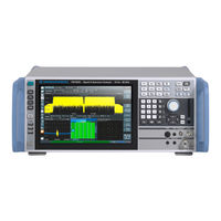
Rohde & Schwarz FSVA3000 User Manual (1489 pages)
Signal and Spectrum Analyzer
Brand:
Rohde & Schwarz
| Category:
Measuring Instruments
| Size: 31.41 MB
Table of Contents
Table of Contents
3
Safety and Regulatory Information
33
Safety Instructions
33
Warning Messages in the Documentation
35
Korea Certification Class a
36
Documentation Overview
37
Getting Started Manual
37
Service Manual
37
User Manuals and Help
37
Data Sheets and Brochures
38
Instrument Security Procedures
38
Printed Safety Instructions
38
Release Notes and Open-Source Acknowledgment (OSA)
38
Application Notes, Application Cards, White Papers, Etc
39
Getting Started
40
Key Features
43
Preparing for Use
43
Choosing the Operating Site
44
Lifting and Carrying
44
Unpacking and Checking
44
Placing the R&S FSV/A on a Bench Top
45
Setting up the R&S FSV/A
45
Connecting the AC Power
46
Mounting the R&S FSV/A in a Rack
46
Switching the Instrument on and off
47
Connecting to LAN
48
Connecting a Keyboard
49
Connecting an External Monitor
49
Windows Operating System
51
Logging on
52
Checking the Supplied Options
54
Performing a Self-Alignment
54
Considerations for Test Setup
55
Protecting Data Using the Secure User Mode
55
Front Panel View
58
Instrument Tour
58
Power Key
58
System Keys
59
Touchscreen
59
Usb
59
Function Keys
61
Navigation Controls
62
Removable Solid State Drive (SSD)
62
Navigation Keys
63
Rotary Knob
63
Undo/Redo Keys
63
Ext Mixer Connector (Optional)
64
Probe
64
RF Input 50 Ohm
64
Trigger Input / Output
64
AF out and Volume (R&S FSV3-B3)
65
Keypad
65
Noise Source Control / Power Sensor
65
Rear Panel View
66
AC Power Supply Connection and Main Power Switch
67
HDMI Display Port
67
Lan
67
GPIB Interface
68
Noise Source Control
68
REF Input / REF Output
68
Trigger 2/3 In/Out
68
Usb
68
Aux. Control
69
Aux. Port
69
IF Output
69
Video Output
69
Device ID
70
External Generator Control Option (R&S FSV3-B10)
70
Labels on R&S FSV/A
70
OCXO Option (R&S FSV3-B4)
70
Measuring a Basic Signal
71
Trying out the Instrument
71
Displaying a Spectrogram
73
Activating Additional Measurement Channels
75
Performing Sequential Measurements
80
Setting and Moving a Marker
81
Displaying a Marker Peak List
83
Zooming into the Display
84
Zooming into the Display Permanently
87
Saving Settings
90
Printing and Saving Results
92
Operating the Instrument
93
Understanding the Display Information
94
Channel Bar
95
Window Title Bar
98
Marker Information
99
Frequency and Span Information in Diagram Footer
100
Error Information
101
Instrument and Status Information
101
Accessing the Functionality
102
Toolbar
102
Context Menus
105
Softkeys
105
On-Screen Keyboard
106
Entering Data
107
Entering Numeric Parameters
107
Entering Alphanumeric Parameters
108
Touchscreen Gestures
110
Activating and Deactivating Channels
113
Displaying Results
113
Laying out the Result Display with the Smartgrid
115
Background Information: the Smartgrid Principle
116
How to Activate Smartgrid Mode
117
How to Add a New Result Window
117
How to Arrange the Result Windows
118
How to Close a Result Window
118
Changing the Size of Windows
119
Switching between a Split and Maximized Window Display
119
Changing the Display
120
Getting Help
120
Applications, Measurement Channels
122
Available Applications
122
Amplifier
123
Fdd Bts
123
Fdd Ue
123
Spectrum
123
AM/FM/PM Modulation Analysis
124
Gsm
124
I/Q Analyzer
124
Lte
124
NB-Iot
124
Phase Noise
125
Pulse Measurements
125
Transient Analysis
125
Vector Signal Analysis (VSA)
125
Wlan
125
R&S Multiview
126
Selecting the Applications
126
Running a Sequence of Measurements
129
The Sequencer Concept
129
How to Set up the Sequencer
131
Sequencer Settings
131
Measurements and Results
133
Auto Measurements
134
Basic Measurement Types
135
Basic Measurements
135
How to Perform a Basic Sweep Measurement
136
Measurement Examples - Measuring a Sinusoidal Signal
138
Measuring the Level and Frequency Using Markers
138
Increasing the Frequency Resolution
139
Setting the Reference Level
139
Measuring the Signal Frequency Using the Signal Counter
140
Measurement Example - Measuring Levels at Low S/N Ratios
141
Measurement Examples - Measuring Signal Spectra with Multiple Signals
144
Separating Signals by Selecting the Resolution Bandwidth
144
Measuring the Modulation Depth of an AM-Modulated Carrier in the Frequency Domain
148
Measuring AM-Modulated Signals
149
Measurement Examples in Zero Span
151
Measuring the Power Characteristic of Burst Signals
151
Measuring the Power of a GSM Burst During the Activation Phase
151
Measuring the Edges of a GSM Burst with High Time Resolution
153
Measuring the Signal-To-Noise Ratio of Burst Signals
155
Channel Power and Adjacent-Channel Power (ACLR) Measurement
156
About Channel Power Measurements
157
Channel Power Results
157
Channel Power Basics
160
Measurement Methods
160
Measurement Repeatability
162
Recommended Common Measurement Parameters
163
Sweep Time
164
Frequency Span
165
Resolution Bandwidth (RBW)
165
Detector
166
Video Bandwidth (VBW)
166
Measurement on Multi-Standard Radio (MSR) Signals
167
Reference Level
167
Trace Averaging
167
Channel Power Configuration
173
General CP/ACLR Measurement Settings
174
Channel Setup
179
MSR ACLR Configuration
182
General MSR ACLR Measurement Settings
183
MSR Sub Block and Tx Channel Definition
188
MSR Adjacent Channel Setup
190
MSR Gap Channel Setup
193
MSR Channel Names
198
How to Perform Channel Power Measurements
199
How to Perform a Standard Channel Power Measurement
200
How to Set up the Channels
200
How to Configure an MSR ACLR Measurement
201
How to Manage User-Defined Configurations
203
How to Compare the Tx Channel Power in Successive Measurements
204
Measurement Example 1 - ACPR Measurement on a CDMA2000 Signal
204
Measurement Examples
204
Measurement Example 2 - Measuring Adjacent Channel Power of a W-CDMA Uplink Signal
206
Measurement Example 3 - Measuring the Intrinsic Noise of the R&S FSV/A with the Channel Power Function
209
Optimizing and Troubleshooting the Measurement
210
Reference: Predefined CP/ACLR Standards
211
Reference: Predefined ACLR User Standard XML Files
212
About the Measurement
214
Carrier-To-Noise Measurements
214
Carrier-To-Noise Configuration
215
Carrier-To-Noise Results
215
How to Determine the Carrier-To-Noise Ratio
217
(Obw)
218
About the Measurement
218
Occupied Bandwidth Measurement (OBW)
218
OBW Results
220
OBW Configuration
221
How to Determine the Occupied Bandwidth
223
Measurement Example
224
About the Measurement
225
Spectrum Emission Mask (SEM) Measurement
225
Typical Applications
225
SEM Results
226
Ranges and Range Settings
229
SEM Basics
229
Limit Lines in SEM Measurements
231
Fast SEM Measurements
234
Multi-Standard Radio (MSR) SEM Measurements
235
SEM with Multiple Sub Blocks ("Multi-SEM")
236
SEM Configuration
239
Multi-Sem Configuration
240
Sweep List
240
Multi-Sem (Sub Block) Settings
246
Reference Range
247
Power Classes
249
MSR Settings
250
Standard Files
253
List Evaluation (Results Configuration)
255
How to Perform a Spectrum Emission Mask Measurement
257
How to Manage SEM Settings Files
260
How to Save SEM Result Files
261
Measurement Example: Multi-Sem Measurement
262
Format Description of SEM XML Files
263
Reference: SEM File Descriptions
263
ASCII File Export Format (Spectrum Emission Mask)
269
About the Measurement
270
Spurious Emissions Measurement
270
Spurious Emissions Measurement Results
271
Ranges and Range Settings
272
Spurious Emissions Basics
272
Limit Lines in Spurious Measurements
273
Spurious Emissions Measurement Configuration
274
Sweep List
274
Adjusting the X-Axis to the Range Definitions
278
List Evaluation
278
How to Perform a Spurious Emissions Measurement
280
Reference: ASCII Export File Format (Spurious)
282
About the Measurements
283
Statistical Measurements (APD, CCDF)
283
APD and CCDF Results
284
Typical Applications
284
APD and CCDF Basics - Gated Triggering
286
APD and CCDF Configuration
288
Basic Settings
288
Gate Range Definition for APD and CCDF
290
Scaling for Statistics Diagrams
291
How to Perform an APD or CCDF Measurement
294
Configuration Example: Gated Statistics
295
Examples
295
Measurement Example - Measuring the APD and CCDF of White Noise Generated by the R&S FSV/A
296
About the Measurement
298
Optimizing and Troubleshooting the Measurement
298
Time Domain Power Measurement
298
Time Domain Power Results
298
Time Domain Power Basics - Range Definition Using Limit Lines
299
Time Domain Power Configuration
300
How to Measure Powers in the Time Domain
302
Measurement Example
302
Harmonic Distortion Measurement
304
About the Measurement
304
Harmonic Distortion Basics
305
Harmonic Distortion Results
307
Harmonic Distortion Configuration
308
How to Determine the Harmonic Distortion
310
Third Order Intercept (TOI) Measurement
310
About the TOI Measurement
311
TOI Basics
311
TOI Results
315
TOI Configuration
316
How to Determine the Third Order Intercept
317
Measurement Example - Measuring the R&S Fsv/A's Intrinsic Intermodulation
318
About the Measurement
320
AM Modulation Depth Measurement
320
AM Modulation Depth Configuration
321
AM Modulation Depth Results
321
Electromagnetic Interference (EMI) Measurement
323
How to Determine the am Modulation Depth
323
Optimizing and Troubleshooting the Measurement
323
About the Emi Measurement
324
EMI Measurement Results
325
EMI Measurement Basics
326
Resolution Bandwidth and Filter Types
326
Detectors and Dwell Time
327
Frequency Resolution - Sweep Points and Scaling
331
Controlling V-Networks (LISN)
332
Initial Measurement - Peak Search
333
Using Transducer Factors
333
Final Measurement at the Marker Position
334
EMI Measurement Configuration
335
Limit Checks
335
EMI Marker Configuration
336
EMI Final Measurement Configuration
339
LISN Control Settings
343
EMI Result Analysis
344
How to Perform EMI Measurements
345
Measurement Example: Measuring Radio Frequency Interference
347
Optimizing and Troubleshooting EMI Measurements
349
Chapter 6 Configuration Overview
350
Common Measurement Settings
350
Data Input and Output
352
Receiving Data Input and Providing Data Output
352
Using Probes
352
RF Probes
353
Receiving and Providing Trigger Signals
355
IF and Video Signal Output
356
Input Source Settings
356
Radio Frequency Input
356
Possible Via the Remote Command Input
357
Input Coupling
357
Radio Frequency State
357
Direct Path
358
Impedance
358
Input Connector
359
Preselector Adjust
359
YIG-Preselector
359
Probe Settings
360
Basics on Power Sensors
362
Power Sensors
362
Using a Power Sensor as an External Power Trigger
363
Power Sensor Settings
364
How to Work with a Power Sensor
368
How to Set up a Power Sensor
369
How to Configure a Power Sensor as an External (PSE) Trigger
370
How to Zero the Power Sensor
370
About External Generator Control
371
Basics on External Generator Control
371
Optional External Generator Control
371
External Generator Connections
372
Overview of Supported Generators
374
Calibration Mechanism
375
Generator Setup Files
375
Normalization
375
Reference Trace, Reference Line and Reference Level
377
Coupling the Frequencies
378
Displayed Information and Errors
380
External Generator Control Settings
381
Interface Configuration Settings
381
Measurement Settings
383
Source Calibration Functions
386
How to Calibrate a Measurement Setup Using an External Generator
389
How to Work with External Generator Control
389
How to Compensate for Additional Gain or Attenuation after Calibration
391
How to Remove the Effects of a Particular Component from Measurement Results Using Calibration
391
Measurement Example: Calibration with an External Generator
392
Basics on External Mixers
397
Frequency Ranges
397
Optional External Mixers
397
Two-Port and Three-Port Mixers
398
Bias Current
399
Conversion Loss Tables
400
External Mixers and Large Bandwidth Extension Options
401
Automatic Signal Identification
403
External Mixer Settings
407
Mixer Settings
407
Basic Settings
411
Managing Conversion Loss Tables
413
Creating and Editing Conversion Loss Tables
415
How to Work with External Mixers
418
Measurement Example 1: Two-Port Mixer
421
Measurement Examples: Using an External Mixer
421
Measurement Example 2: Three-Port Mixer with a Large Analysis Bandwidth
422
External Frontend Basics
424
External Frontend Control (R&S FSV3-K553)
424
External Frontend Settings
429
Global Configuration Settings
429
Frontend Configuration Settings
431
Diagnostics
434
Network Configuration
435
How to Use an External Frontend
436
Error Messages
437
Troubleshooting External Frontend Control
437
Problems During Operation
439
Problems with Connection
439
Output Settings
440
Audio Output
441
If/Video Output
441
Trigger Input/Output Settings
443
How to Output a Trigger Signal
445
Frequency and Span Configuration
446
Impact of the Frequency and Span Settings
446
Defining the Scope of the Measurement - Frequency Range
447
Frequency and Span Settings
447
Stepping through the Frequency Range - Center Frequency Stepsize
447
Keeping the Center Frequency Stable - Signal Tracking
451
How to Define the Frequency Range
452
How to Move the Center Frequency through the Frequency Range
452
Amplitude and Vertical Axis Configuration
453
Impact of the Vertical Axis Settings
453
Reference Level
453
RF Attenuation
454
Amplitude Settings
455
Scaling
455
Scaling the Y-Axis
460
How to Optimize the Amplitude Display
462
Bandwidth, Filter and Sweep Configuration
463
Impact of the Bandwidth, Filter and Sweep Settings
463
Separating Signals by Selecting an Appropriate Resolution Bandwidth
464
Coupling VBW and RBW
465
Smoothing the Trace Using the Video Bandwidth
465
Coupling Span and RBW
466
How Data Is Measured: the Sweep Type
466
How Long the Data Is Measured: Sweep Time
468
Which Data May Pass: Filter Types
468
How Much Data Is Measured: Sweep Points and Sweep Count
469
How Often Data Is Measured: Sweep Mode
469
Bandwidth, Filter and Sweep Settings
470
Reference: List of Available RRC and Channel Filters
478
Trigger and Gate Configuration
480
Triggered Measurements
480
Triggering
480
Trigger Hysteresis
481
Trigger Offset
481
Trigger Source
481
Trigger Drop-Out Time
482
Trigger Holdoff
483
Trigger Settings
484
How to Determine the Required Trigger/Gate Parameters
490
How to Configure a Triggered Measurement
491
Gated Measurements
492
Gating
492
Gate Settings
494
Continuous Gate Settings
496
How to Configure a Gated Measurement
497
Adjusting Settings Automatically
498
Basic Evaluation Methods
502
Common Analysis and Display Functions
502
Result Display Configuration
502
Background Information: the Smartgrid Principle
505
Laying out the Result Display with the Smartgrid
505
How to Activate Smartgrid Mode
507
How to Add a New Result Window
507
How to Arrange the Result Windows
508
How to Close a Result Window
508
Single Zoom Versus Multiple Zoom
509
Zoomed Displays
509
Zoom Functions
511
How to Zoom into a Diagram
513
Basics on Markers
516
Marker Usage
516
Activating Markers
518
Marker Results
518
Marker Types
518
Marker Settings
519
Individual Marker Setup
520
General Marker Settings
523
Marker Search Settings
525
Marker Search Settings and Positioning Functions
525
Marker Search Settings for Spectrograms
528
Positioning Functions
531
Marker (Measurement) Functions
533
Precise Frequency (Signal Count) Marker
533
Measuring Noise Density (Noise Meas Marker)
535
Phase Noise Measurement Marker
538
Measuring Characteristic Bandwidths (N Db down Marker)
541
Fixed Reference Marker
543
Measuring the Power in a Channel (Band Power Marker)
544
Demodulating Marker Values and Providing Audio Output (Marker Demodulation)
547
Marker Peak List
550
Deactivating All Marker Functions
554
How to Analyze a Signal Point in Detail
554
How to Work with Markers
554
How to Output the Demodulated Signal Accoustically
555
How to Use a Fixed Reference Marker
555
How to Export a Peak List
556
Measurement Example: Measuring Harmonics Using Marker Functions
557
Display and Limit Lines
558
Basics on Display Lines
559
Display Line Settings
559
Display Lines
559
Defining Display Lines
560
Basics on Limit Lines
561
Limit Lines
561
Limit Line Management
565
Limit Line Settings and Functions
565
Limit Line Details
568
How to Define Limit Lines
572
Reference: Limit Line File Format
576
Basics on Setting up Traces
577
Mapping Samples to Sweep Points with the Trace Detector
577
Standard Traces
577
Trace Configuration
577
X-Value of the Sweep Point
581
Analyzing Several Traces - Trace Mode
582
How Many Traces Are Averaged - Sweep Count + Sweep Mode
583
How Trace Data Is Averaged - the Averaging Mode
584
Trace Smoothing
585
Trace Settings
586
How to Configure a Standard Trace
591
Spectrograms
592
Working with Spectrograms
592
Time Frames
594
Markers in the Spectrogram
596
Three-Dimensional Spectrograms
596
Color Maps
598
General Spectrogram Settings
601
Spectrogram Settings
601
Color Map Settings
604
How to Display and Configure a Spectrogram
606
How to Configure the Color Mapping
608
Trace Math
610
Importing and Exporting Measurement Results for Evaluation
612
Displaying a Reference Trace - Importing Trace Data
613
Trace/Data Ex/Import
614
How to Export Trace Data and Numerical Results
619
How to Import Traces
619
How to Export a Peak List
620
Event-Based Actions
621
Reference: ASCII File Export Format
621
Managing Rules
622
Defining Rules
623
Debugging Rules with the EBA-Journal
629
Reference: Overview of Available Result-Events and State-Events
631
Improving Averaging Results
632
Minimizing the Measurement Duration
632
Optimizing Measurements
632
Data Management
634
Restoring the Default Instrument Configuration (Preset)
634
Protecting Data Using the Secure User Mode
635
Storing and Recalling Instrument Settings and Measurement Data
637
Quick Save / Quick Recall Settings
639
Quick Save/Quick Recall
639
Configurable Storage and Recall
641
Stored Data Types
641
Save and Recall Dialog Boxes
642
Storage Location and Filename
642
Startup Recall Settings
645
How to Save and Load Instrument Settings
647
Import/Export Functions
649
Creating Screenshots of Current Measurement Results and Settings
653
Print and Screenshot Settings
653
Print Content Settings
654
Print Preview Functions
656
Printer Settings
658
Page Setup
661
Print Color Settings
663
How to Store or Print Screenshots of the Display
664
Example for Storing Multiple Measurement Results to a PDF File
666
Working with Test Reports
668
Designing a Test Report Template
669
General Contents
671
Title Page
672
Measurement Information
675
Application-Specific Contents
677
Creating Datasets
678
Managing Templates
678
Creating a Test Report
679
How to Create a Test Report
681
Alignment
684
Basics on Alignment
684
General Instrument Setup
684
Alignment Settings
686
How to Align the Instrument
690
How to Perform a Self-Test
690
Display Settings
691
General Display Settings
691
How to Align the Touchscreen
691
Displayed Items
693
Display Theme and Colors
696
External Monitor Settings
701
How to Configure the Colors for Display and Printing
702
Touch(Screen) Settings
702
How to Work with the Soft Front Panels
703
Application Starter
704
Application Starter Functions
705
How to Work with the Application Starter
709
Toolbar Configuration
710
Basics on Transducer Factors
712
Transducers
712
Transducer Management
714
Transducer Settings
714
Transducer Factors
717
How to Configure the Transducer
720
Reference: Transducer Factor File Format
720
Basics on Frequency Response Correction
724
Frequency Response Correction (R&S FSV/A-K544)
724
User-Defined Frequency Response Correction Settings
728
Reference Frequency Settings
736
Hardware Information
739
System Configuration Settings
739
Licensing, Versions and Options
740
Obtaining Copyright Information on Used Third-Party Sources
740
License Management
741
System Messages
745
Firmware Updates
746
General Configuration Settings
748
Signal Generator Settings
750
Service Functions
751
R&S Support Information
752
Calibration Signal Display
754
Self-Test Settings and Results
754
Service Functions
756
Hardware Diagnostics
758
General Parameter Coupling
759
Synchronizing Measurement Channel Configuration
759
User-Defined Parameter Coupling
762
Generator Coupling
766
How to Synchronize Parameters
768
Example for a User-Defined Parameter Coupling
770
Network Operation and Remote Control
773
Remote Control Interfaces and Protocols
773
LAN Interface
774
LAN Web Browser Interface
775
Hierarchy of Status Registers
777
Status Reporting System
777
Contents of the Status Registers
778
Status Byte (STB) and Service Request Enable Register (SRE)
779
Event Status Register (ESR) and Event Status Enable Register (ESE)
780
IST Flag and Parallel Poll Enable Register (PPE)
780
Status:operation Register
781
Status:questionable Register
782
Status:questionable:acplimit Register
783
Status:questionable:extended Register
784
Status:questionable:extended:info Register
785
Status:questionable:frequency Register
785
Status:questionable:limit Register
786
Status:questionable:lmargin Register
786
Status:questionable:power Register
787
Status:questionable:temperature Register
788
Status:questionable:time Register
788
Reset Values of the Status Reporting System
789
GPIB Languages
790
The IECWIN Tool
792
Automating Tasks with Remote Command Scripts
793
The Context-Sensitive SCPI Command Menu
794
The SCPI Recorder
796
How to Determine the Required SCPI Command
800
How to Create and Export SCPI Scripts
801
Example for a Recorded SCPI Script
804
Network and Remote Control Settings
804
General Network Settings
805
Remote Settings
807
Compatibility Settings
810
LAN Settings
814
HUMS Settings
815
Basic Settings
816
Protocol Settings
817
Device Tags
820
Remote Errors
821
How to Set up a Network and Remote Control
823
Returning to Manual Mode ("Local")
823
How to Configure a Network
824
How to Connect the Instrument to the Network
824
How to Assign the IP Address
825
How to Change the Instrument Name
827
How to Configure the LAN Using the Web Browser Interface
828
LAN Configuration
829
How to Change the GPIB Instrument Address
830
How to Log on to the Network
830
How to Operate the Instrument Without a Network
830
How to Change the User Password
831
How to Create Users
831
How to Configure the Automatic Login Mechanism
832
How to Control the R&S FSV/A Via the Web Browser Interface
833
How to Share Directories (Only with Microsoft Networks)
833
How to Deactivate the Web Browser Interface
835
How to Configure the R&S FSV/A for Remote Operation Via Remote Desktop
836
How to Set up Remote Desktop
836
How to Configure the Controller
837
How to Start and Close the Remote Desktop
840
How to Shut down the R&S FSV/A Via Remote Operation
842
How to Start a Remote Control Session from a PC
842
How to Return to Manual Operation
843
Conventions Used in SCPI Command Descriptions
844
Remote Commands
844
Common Commands
845
Common Suffixes
845
Selecting the Mode and Applications
850
Selecting the Operating Mode and Application
850
Performing a Sequence of Measurements
854
Programming Example: Performing a Sequence of Measurements
856
Configuring and Performing Measurements
858
Performing Measurements
859
Configuring Power Measurements
862
Measuring the Channel Power and ACLR
866
Managing Measurement Configurations
867
Configuring the Channels
868
Defining Weighting Filters
872
Selecting the Reference Channel
874
Checking Limits
875
General ACLR Measurement Settings
881
Configuring MSR ACLR Measurements
882
General MSR ACLR Measurement Settings
882
MSR Sub Block and Tx Channel Setup
883
MSR Adjacent Channel Setup
885
General Gap Channel Setup
890
Automatic (Symmetrical) Configuration
892
Manual (Asymmetrical) Configuration
897
MSR Channel Names
911
Performing an ACLR Measurement
912
Retrieving and Analyzing Measurement Results
912
Example: Configuring and Performing an ACLR Measurement
916
Programming Examples for Channel Power Measurements
916
Example: Configuring and Performing an MSR ACLR Measurement
918
Example: Configuring and Performing an Asymmetrical MSR ACLR Measurement
920
Measuring the Carrier-To-Noise Ratio
924
Configuring the Measurement
925
Measuring the Occupied Bandwidth
925
Programming Example: OBW Measurement
926
Managing Measurement Configurations
927
Measuring the Spectrum Emission Mask
927
Configuring a Multi-Sem Measurement
929
Controlling the Measurement
929
Configuring a Sweep List
930
Configuring the Reference Range
945
Configuring the Power Classes
946
Configuring MSR SEM Measurements
951
Configuring the List Evaluation
957
Example: SEM Measurement
959
Performing an SEM Measurement
959
Retrieving Results
959
Measuring Spurious Emissions
962
Configuring a Sweep List
963
Initializing the Measurement
963
Configuring the List Evaluation
972
Adjusting the X-Axis to the Range Definitions
974
Performing a Spurious Measurement
974
Programming Example: Spurious Emissions Measurement
974
Retrieving and Saving Settings and Results
974
Activating Statistical Measurements
977
Analyzing Statistics (APD, CCDF)
977
Configuring Statistical Measurements
978
Using Gate Ranges for Statistical Measurements
979
Scaling the Diagram
981
Performing a Statistical Measurement
984
Retrieving Results
984
Programming Example: Measuring Statistics
985
Configuring the Measurement
987
Measuring the Time Domain Power
987
Performing a Time Domain Power Measurement
990
Measuring the Mean Power
991
Retrieving Measurement Results
991
Measuring the Peak Power
992
Measuring the RMS Power
993
Measuring the Standard Deviation
994
Programming Example: Time Domain Power
996
Activating the Measurement
997
Configuring the Measurement
997
Measuring the Harmonic Distortion
997
Performing the Measurement
999
Retrieving Results
999
Example: Measuring the Harmonic Distortion
1000
Determining the TOI
1001
Measuring the Third Order Intercept Point
1001
Programming Example: Measuring the TOI
1003
Configuring and Performing the Measurement
1004
Measuring the am Modulation Depth
1004
Example: Measuring the am Modulation Depth
1005
Activating EMI Measurement
1006
Remote Commands for EMI Measurements
1006
Configuring EMI Markers
1007
Configuring the EMI Final Test
1008
Configuring EMI Limit Lines
1009
Controlling LISN
1009
Retrieving EMI Results
1011
Evaluating the Results
1013
Programming Example: EMI Measurement
1013
List Evaluations
1015
Performing List Evaluations
1016
Example: Performing List Evaluation
1019
Measuring the Pulse Power
1020
Performing Pulse Power Measurements
1021
Configuring the Result Display
1024
Example: Performing a Pulse Power Measurement
1024
General Window Commands
1025
Working with Windows in the Display
1026
Example 1: Adding and Arranging Windows
1033
Examples: Configuring the Result Display
1033
Example 2: Replacing and Removing Windows
1034
Setting Basic Measurement Parameters
1035
Configuring the Data Input and Output
1036
RF Input
1036
Commands for Initial Configuration
1040
Remote Commands for External Frontend Control
1040
Commands for Test, Alignment, and Diagnosis
1047
Format of Selftest Result File
1049
Programming Example: Configuring an External Frontend
1053
Basic Settings
1055
Using External Mixers
1055
Mixer Settings
1057
Conversion Loss Table Settings
1064
Programming Example: Working with an External Mixer
1068
Setting up Probes
1070
External Generator Control
1075
Measurement Configuration
1076
Interface Configuration
1079
Source Calibration
1081
Programming Example for External Generator Control
1084
Configuring Power Sensors
1086
Working with Power Sensors
1086
Configuring Power Sensor Measurements
1087
Triggering with Power Sensors
1094
Configuring the Outputs
1097
Defining the Frequency and Span
1100
Defining the Frequency Range
1101
Configuring Signal Tracking
1105
Configuring Bandwidth and Sweep Settings
1107
Configuring the Bandwidth and Filter
1107
Configuring the Sweep
1110
Amplitude Settings
1115
Configuring the Vertical Axis (Amplitude, Scaling)
1115
Configuring the Attenuation
1118
Configuring a Preamplifier
1120
Scaling the Y-Axis
1122
Configuring the Triggering Conditions
1125
Configuring Triggered and Gated Measurements
1125
Configuring Gated Measurements
1130
Configuring the Trigger Output
1134
Adjusting Settings Automatically
1136
Analyzing Measurements (Basics)
1140
Using the Single Zoom
1140
Zooming into the Display
1140
Using the Multiple Zoom
1142
Configuring the Trace Display and Retrieving Trace Data
1143
Configuring Standard Traces
1144
Configuring a Spectrogram Measurement
1151
Configuring Spectrograms
1151
Configuring the Color Map
1157
Using Trace Mathematics
1159
Chapter 12 Retrieving Trace Results
1161
Formats for Returned Values: ASCII Format and Binary Format
1163
Importing and Exporting Traces
1164
Programming Example: Configuring a Spectrogram
1167
Setting up Individual Markers
1170
Working with Markers
1170
General Marker Settings
1177
Configuring and Performing a Marker Search
1179
Positioning Normal Markers
1183
Positioning the Marker
1183
Positioning Delta Markers
1186
Retrieving Marker Results
1189
Marker Search (Spectrograms)
1191
Using Markers
1191
Using Delta Markers
1195
Fixed Reference Marker Settings
1200
Marker Peak Lists
1202
Noise Measurement Marker
1205
Phase Noise Measurement Marker
1207
Band Power Marker
1209
Using Markers
1210
Using Delta Markers
1212
N Db down Marker
1213
Signal Count Marker
1217
Marker Demodulation
1218
Programming Examples for Using Markers and Marker Functions
1221
Example: Basic Markers
1222
Example: Marker Search in Spectrograms
1223
Basic Frequency Sweep Measurement for Marker Function Examples
1224
Example: Using a Fixed Reference Marker
1224
Example: Measuring Noise Density
1225
Example: Obtaining a Marker Peak List
1225
Example: Measuring Phase Noise
1226
Example: Measuring Characteristic Bandwidths (Using the N Db down Marker)
1227
Example: Measuring the Power in a Channel Using Band Power Markers
1227
Examples: Demodulating Marker Values and Providing Audio Output
1228
Example: Performing a Highly Accurate Frequency Measurement Using the Signal Count Marker
1229
Configuring Display Lines
1230
Defining Limit Checks
1232
Configuring Limit Lines
1233
Managing Limit Lines
1242
Checking the Results of a Limit Check
1245
Example: Configuring Limit Lines
1246
Programming Example: Using Limit Lines
1246
Example: Performing a Limit Check
1248
Managing Settings and Results
1249
General Data Storage and Loading Commands
1250
Selecting the Items to Store
1256
Storing and Loading Instrument Settings
1259
Storing or Printing Screenshots
1264
Storing Measurement Results
1275
Test Reports
1278
Examples: Managing Data
1286
Storing Data
1286
Loading Data
1287
Loading Instrument Settings
1287
Storing Instrument Settings
1287
Printing on a Printer
1288
Printing to a File
1288
Storing Multiple Graphical Measurement Results to a PDF File
1289
Configuring the R&S FSV/A
1290
Configuring the Reference Frequency
1290
Calibration and Checks
1293
Working with Transducers
1297
Compensating for Frequency Response Using Touchstone Files (R&S FSV/A-K544)
1301
Remote Commands for Frequency Response Correction
1301
Customizing the Screen Layout
1319
General Display Settings and Items
1319
Programming Example: Using Touchstone Files
1319
Colors and Themes
1323
CMAP Suffix Assignment
1325
Remote Commands for Language Settings
1326
Configuring the Network and Remote Control
1327
Configuring HUMS
1331
Checking the System Configuration
1337
Signal Generator Control Commands
1346
Using Service Functions
1347
Predefined Parameter Coupling
1349
Remote Commands for Synchronizing Parameters
1349
User-Defined Parameter Coupling
1356
Generator Coupling
1364
Configuring the Application Starter
1366
General Status Register Commands
1369
Using the Status Register
1369
Reading out the Condition Part
1370
Reading out the Event Part
1370
Controlling the Enable Part
1371
Controlling the Negative Transition Part
1371
Controlling the Positive Transition Part
1372
Commands for Remote Instrument Operation
1373
Emulating Other Instruments' Commands
1373
Setting up Instrument Emulation
1374
Command Set of Models 8560E, 8561E, 8562E, 8563E, 8564E, 8565E, 8566A/B, 8568A/B, 8591E, 8594E, 71100C, 71200C, and 71209A
1377
Reference: GPIB Commands of Emulated HP Models
1377
Special Features of the Syntax Parsing Algorithms for 8566A and 8568A Models
1401
Special Behavior of Commands
1402
Model-Dependent Default Settings
1403
Data Output Formats
1404
GPIB Status Reporting
1404
Trace Data Input Formats
1404
Trace Data Output Formats
1404
Reference: Command Set of Emulated PSA Models
1405
Reference: Command Set of Emulated PXA Models
1409
Deprecated Commands
1411
Programming Examples
1414
Programming Example: Performing a Basic Frequency Sweep
1415
Initiate Service Request
1418
Service Request
1418
Waiting for the Arrival of a Service Request
1420
Waiting Without Blocking the Keyboard and Mouse
1421
Service Request Routine
1422
Reading out the Output Buffer
1423
Evaluation of SCPI Status Registers
1424
Reading Error Messages
1424
Evaluation of Event Status Register
1425
Error Information
1427
Troubleshooting
1427
Error Messages in Remote Control Mode
1428
Troubleshooting Remote Operation
1429
Miscellaneous Troubleshooting Hints
1431
System Recovery
1432
Collecting Information for Support
1433
Contacting Customer Support
1435
Transporting
1436
Cleaning
1437
Maintenance, Storage, Transport and Disposal
1437
Storage
1437
Transporting
1437
Disposal
1438
List of Remote Commands (Base Unit)
1439
Index
1464
Advertisement
Rohde & Schwarz FSVA3000 User Manual (373 pages)
Pulse Measurement Option
Brand:
Rohde & Schwarz
| Category:
Measuring Instruments
| Size: 7.41 MB
Table of Contents
Table of Contents
3
1 Preface
7
Documentation Overview
7
Basic Safety Instructions
8
Service Manual
8
About this Manual
9
Conventions Used in the Documentation
9
2 Welcome to the Pulse Measurements Application
11
Starting the Pulse Application
11
Understanding the Display Information
12
3 Measurements and Result Displays
15
Pulse Parameters
15
Evaluation Methods for Pulse Measurements
29
4 Measurement Basics
42
Parameter Definitions
42
Pulse Detection
45
Parameter Spectrum Calculation
47
Basics on Input from I/Q Data Files
50
Trace Evaluation
51
5 Configuration
56
Configuration Overview
56
Signal Description
58
Input and Output Settings
61
Output Settings
64
Frontend Settings
65
Input 5.5 Trigger Settings
71
Trigger Settings
71
Trigger Source
72
Free Run
72
External Trigger 1/2
72
I/Q Power
72
IF Power
73
RF Power
73
Drop-Out Time
73
Trigger Level
73
Hysteresis
74
Slope
74
Trigger Holdoff
74
Trigger Offset
74
Data Acquisition
76
Sweep Settings
79
Pulse Detection
80
Pulse Measurement Settings
83
Automatic Settings
90
6 Analysis
91
Result Configuration
91
Display Configuration
107
Markers
108
Trace Configuration
115
Section 5
116
Detector
117
Hold
117
Trace 1/Trace 2/Trace 3/Trace 4/Trace 5/Trace 6
117
Trace Mode
117
Evaluation
118
Selected Pulse Vs All Pulses
118
Statistical Evaluation
118
Normalization
119
Predefined Trace Settings - Quick Config
119
Trace 1 / Trace 2 / Trace 3 / Trace 4 (Softkeys)
119
Trace / Data Export Configuration
120
Export Functions
121
Section 6
122
Decimal Separator
123
Export Table to ASCII File
123
Export Trace to ASCII File
124
I/Q Export
124
Export Range
125
7 Export Functions
126
Trace Export Configuration
124
How to Perform a Standard Pulse Measurement
130
8 How to Perform Measurements in the Pulse Application
130
How to Configure a Limit Check for a Pulse Measurement
131
How to Export Table Data
132
9 Remote Commands for Pulse Measure- Ments
134
9 Remote Commands for Pulse Measurements
134
Introduction
134
Common Suffixes
139
Activating Pulse Measurements
140
Signal Description
143
Input/Output Settings
146
Frontend Configuration
152
Triggering Measurements
159
Data Acquisition
166
Pulse Detection
168
Configuring the Pulse Measurement
171
Rohde & Schwarz FSVA3000 Getting Started (124 pages)
Signal and Spectrum Analyzer
Brand:
Rohde & Schwarz
| Category:
Measuring Instruments
| Size: 7.39 MB
Table of Contents
Table of Contents
5
1 Preface
7
Key Features
7
Conventions Used in the Documentation
8
2 Safety Information
10
3 Documentation Overview
11
Getting Started Manual
11
User Manuals and Help
11
Basic Safety Instructions
12
Data Sheets and Brochures
12
Instrument Security Procedures
12
Service Manual
12
Application Notes, Application Cards, White Papers, Etc
13
4 Preparing for Use
14
Release Notes and Open Source Acknowledgment (OSA)
13
Putting into Operation
14
Windows Operating System
22
Connecting USB Devices
27
Connecting an External Monitor
29
Setting up a Network (LAN) Connection
30
Configuring the Initial Instrument Settings
37
Protecting Data Using the Secure User Mode
37
5 Instrument Tour
41
Front Panel View
41
Rear Panel View
52
6 Trying out the Instrument
58
Measuring a Basic Signal
58
Displaying a Spectrogram
60
Activating Additional Measurement Channels
62
Performing Sequential Measurements
67
Setting and Moving a Marker
68
Displaying a Marker Peak List
70
Zooming into the Display
71
Zooming into the Display Permanently
75
Saving Settings
78
Printing and Saving Results
80
7 Operating the Instrument
82
Understanding the Display Information
83
Channel Bar
84
Window Title Bar
88
Marker Information
89
Frequency and Span Information in Diagram Footer
90
Instrument and Status Information
90
Error Information
91
Accessing the Functionality
92
Entering Data
98
Touchscreen Gestures
102
Displaying Results
106
Getting Help
115
Remote Control
116
8 Contacting Customer Support
119
Index
120
Advertisement
Advertisement
Related Products
Rohde & Schwarz FSVA30
Rohde & Schwarz FSVA3004
Rohde & Schwarz FSVA3007
Rohde & Schwarz FSVA3013
Rohde & Schwarz FSVA3030
Rohde & Schwarz FSVA3044
Rohde & Schwarz FSVA
Rohde & Schwarz FSVA4
Rohde & Schwarz FSVA7
Rohde & Schwarz FSVA13
Rohde & Schwarz Categories
Measuring Instruments
Test Equipment
Power Supply
Portable Generator
Accessories
More Rohde & Schwarz Manuals
Login
Sign In
OR
Sign in with Facebook
Sign in with Google
Upload manual
Upload from disk
Upload from URL