Table of Contents
Advertisement
Quick Links
Advertisement
Chapters
Table of Contents

Related Manuals for Rohde & Schwarz R&S FSW-K30


Summary of Contents for Rohde & Schwarz R&S FSW-K30
- Page 1 ® R&S FSW-K30 Noise Figure Measurements User Manual (;×êÔ2) 1173927002 Version 31...
- Page 2 This manual applies to the following FSW models with firmware version 6.00 and later: ● R&S ® FSW8 (1331.5003K08 / 1312.8000K08) ● ® R&S FSW13 (1331.5003K13 / 1312.8000K13) ● ® R&S FSW26 (1331.5003K26 / 1312.8000K26) ● R&S ® FSW43 (1331.5003K43 / 1312.8000K43) ●...
-
Page 3: Table Of Contents
® Contents R&S FSW-K30 Contents 1 Preface....................9 About this manual......................9 Conventions used in the documentation..............10 1.2.1 Typographical conventions....................10 1.2.2 Conventions for procedure descriptions................10 1.2.3 Notes on screenshots....................10 2 Welcome to the noise figure measurement application....11 Starting the noise application..................11 Understanding the display information.............. - Page 4 ® Contents R&S FSW-K30 5.2.2 Configuring single frequency measurements..............49 5.2.3 Using a frequency table....................50 Selecting DUT characteristics................... 53 Configuring the noise source..................54 5.4.1 Defining the noise source characteristics..............54 5.4.2 Using an ENR or temperature table................58 Configuring additional loss..................62 5.5.1 Defining loss........................62 5.5.2...
- Page 5 ® Contents R&S FSW-K30 6.4.2 Marker positioning.......................105 Limit line settings and functions................106 6.5.1 Limit line management....................107 6.5.2 Limit line details......................109 7 Remote control commands for noise figure measurements..111 Common suffixes...................... 112 Introduction....................... 112 7.2.1 Conventions used in descriptions................113 7.2.2 Long and short form....................
- Page 6 ® Contents R&S FSW-K30 7.14 Performing measurements..................184 7.15 Configuring the inputs and outputs................ 189 7.15.1 Radio frequency (RF) input..................189 7.15.2 External generator.......................191 7.15.3 Remote commands for external frontend control............195 7.15.3.1 Commands for initial configuration................195 7.15.3.2 Commands for test, alignment, and diagnosis............204 7.16 Configuring the display....................
- Page 7 ® Contents R&S FSW-K30 A Reference: frequency table file format..........243 List of Commands (Noise Figure).............244 Index....................251 User Manual 1173.9270.02 ─ 31...
- Page 8 ® Contents R&S FSW-K30 User Manual 1173.9270.02 ─ 31...
-
Page 9: Preface
® Preface R&S FSW-K30 About this manual 1 Preface 1.1 About this manual This User Manual provides all the information specific to the application. All general instrument functions and settings common to all applications and operating modes are described in the main FSW User Manual. The main focus in this manual is on the measurement results and the tasks required to obtain them. -
Page 10: Conventions Used In The Documentation
® Preface R&S FSW-K30 Conventions used in the documentation 1.2 Conventions used in the documentation 1.2.1 Typographical conventions The following text markers are used throughout this documentation: Convention Description "Graphical user interface ele- All names of graphical user interface elements on the screen, such as ments"... -
Page 11: Welcome To The Noise Figure Measurement Application
® Welcome to the noise figure measurement application R&S FSW-K30 Starting the noise application 2 Welcome to the noise figure measurement application The R&S FSW-K30 is a firmware application that adds functionality to perform "noise figure" measurements to the FSW. Noise Source Control The Noise Source Control connector on the FSW is a prerequisite for the R&S FSW Noise measurements application. -
Page 12: Understanding The Display Information
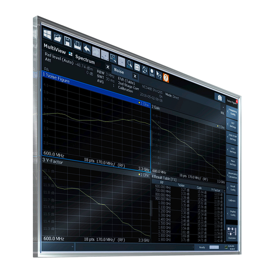
® Welcome to the noise figure measurement application R&S FSW-K30 Understanding the display information Multiple Channels and Sequencer Function When you activate an application, a new channel is created which determines the measurement settings for that application ("Channel"). The same application can be activated with different measurement settings by creating several "Channel"s for the same application. - Page 13 ® Welcome to the noise figure measurement application R&S FSW-K30 Understanding the display information 1 = Toolbar 2 = Channel bar 3 = Diagram header 4 = Result display 5 = Softkey bar 6 = Status bar Channel bar information In the R&S FSW Noise measurements application, the FSW shows the following set- tings: Ref Level...
- Page 14 ® Welcome to the noise figure measurement application R&S FSW-K30 Understanding the display information Risk of damaging the instrument Make sure not to overload the input mixer during calibration and the measurement. An overload condition can damage or destroy the input mixer. If an overload condition occurs, the FSW shows a corresponding message in the sta- tus line ("RF OVLD"...
-
Page 15: Measurements And Result Displays
® Measurements and result displays R&S FSW-K30 3 Measurements and result displays The R&S FSW-K30 measures the "Noise Figure" of a DUT and displays the results graphically and numerically. Each graphical result display shows the "Noise Figure" from a different perspective. In the default configuration, the application shows the "Noise Figure"... -
Page 16: Noise Figure
® Measurements and result displays R&S FSW-K30 Single frequency measurements In all graphical result displays, the horizontal axis represents a chronological order of measurement results for the frequency you are testing. The axis has no unit, but is made up out of several index values that represent time. Each index value represents one measurement point and therefore one measurement on the single frequency you are analyzing. -
Page 17: Gain
® Measurements and result displays R&S FSW-K30 Remote command: LAY:ADD:WIND? '2',RIGH,NOIS see on page 122 LAYout:ADD[:WINDow]? Results:TRACe<t>[:DATA]? <Trace>,NOISe Gain Shows the "Gain" characteristics of the DUT. The vertical axis shows the level of the "Gain" in dB. The scale depends on the set- tings in the "Display Configuration"... -
Page 18: Y-Factor
® Measurements and result displays R&S FSW-K30 Noise Temperatur with Power Bandwidth Boltzmann constant The vertical axis shows the "Temperature" in Kelvin. The scale depends on the settings in the "Display Configuration" dialog box. Remote command: LAY:ADD:WIND? '2',RIGH,TEMP see on page 122 LAYout:ADD[:WINDow]? -
Page 19: Enr Measured
® Measurements and result displays R&S FSW-K30 Remote command: LAY:ADD:WIND? '2',RIGH,YFAC see on page 122 LAYout:ADD[:WINDow]? Results: TRACe<t>[:DATA]? <Trace>,YFACtor ENR Measured Shows the results of the ENR measurement. To measure the ENR of a noise source, first attach a noise source with known ENR to the device, enter the ENR of this noise source to the calibration ENR table and cali- brate using this one. -
Page 20: Level (Hot)
® Measurements and result displays R&S FSW-K30 Remote command: LAY:ADD:WIND? '2',RIGH,ENR see on page 122 LAYout:ADD[:WINDow]? Results: TRACe<t>[:DATA]? <Trace>,ENR Level (Hot) Shows the absolute power characteristics at the instrument input. The noise source is turned on. The vertical axis shows the power in dBm. The scale depends on the settings in the "Display Configuration"... -
Page 21: Cal Y-Factor
® Measurements and result displays R&S FSW-K30 Remote command: LAY:ADD:WIND? '2',RIGH,PCOL see on page 122 LAYout:ADD[:WINDow]? Results: TRACe<t>[:DATA]? <Trace>,PCOLd Cal Y-Factor Shows the ratio of the hot and the cold power measured during calibration. The "Y-factor" indicates the quality of measurement tolerances and uncertainties. To get the result, the application measures the power with the noise source turned on (hot power) and the noise source turned off (cold power), but without the DUT inserted. -
Page 22: Cal Level (Hot)
® Measurements and result displays R&S FSW-K30 Cal Level (Hot) Shows the absolute power characteristics at the instrument input during the calibration measurement. The noise source is turned on, the DUT is not inserted. The vertical axis shows the power in dBm. The scale depends on the settings in the "Display Configuration"... -
Page 23: P Hot
® Measurements and result displays R&S FSW-K30 Remote command: LAY:ADD:WIND? '2',RIGH,CPC see on page 122 LAYout:ADD[:WINDow]? Results: TRACe<t>[:DATA]? <Trace>,CPCold P Hot Shows the relative power with a hot noise source in dB. The scale depends on the settings in the "Display Configuration" dialog box. Remote command: LAY:ADD? '1',RIGH,DPH, see on page 122... -
Page 24: Result Table
® Measurements and result displays R&S FSW-K30 Remote command: LAY:ADD? '1',RIGH,DPC, see on page 122 LAYout:ADD[:WINDow]? Results: TRACe<t>[:DATA]? <Trace>,DPCold Result Table Shows the measurement results in numerical form in a table. The contents of the table depend on the "Display Settings". By default it shows the "Noise Figure", "Gain"... - Page 25 ® Measurements and result displays R&S FSW-K30 The first four columns of the table are fix. ● Type Shows the marker type. 'M' represents a normal marker, 'D' represents a delta marker. ● Shows the reference marker for relative delta markers. ●...
-
Page 26: Measurement Basics
® Measurement basics R&S FSW-K30 Tuning modes 4 Measurement basics The measurement basics contain background information on the terminology and prin- ciples of "noise figure" measurements. "Noise figure" measurements determine the noise that a device under test (DUT) adds to a signal as that signal passes through the DUT. ●... -
Page 27: Swept Measurements
® Measurement basics R&S FSW-K30 Tuning modes 4.1.1 Swept measurements The sweep tuning mode performs measurements on a set of discrete frequencies based on the frequency parameters. Each measurement analyzes the noise character- istics of the corresponding frequency or measurement point. For swept measurements, the application automatically determines the measurement frequencies and combines them in a frequency list. -
Page 28: Measurement Modes
® Measurement basics R&S FSW-K30 Measurement modes Single frequency measurements are a way to facilitate manual adjustments for "noise figure" measurements. They also allow you to get an idea about how the "noise figure" at a particular frequency change over time. Note that sweep lists or frequency tables are not considered in this measurement mode. - Page 29 ® Measurement basics R&S FSW-K30 Measurement modes Recommended order of measurements Note that it is recommended that you begin with the hot power measurement. Furthermore, calibration always begins with the hot power measurement. In case the hot power has to be measured first, the cold power measurement is unavailable: When the first measurement is done, you can change the test setup by connecting the other resistor.
-
Page 30: Dut Types
® Measurement basics R&S FSW-K30 DUT types Returning to automatic measurement mode When you are in automatic measurement mode and select a noise source with resistor characteristics, the application automatically selects the manual measurement mode. When you are in manual measurement mode and select a noise source with diode characteristics, you have to select the automatic measurement mode deliberately in the "Sweep"... -
Page 31: External Generator Control
® Measurement basics R&S FSW-K30 External generator control If you have selected a frequency-converting DUT measurement mode, the layout of the "Overview" dialog box adds the local oscillator to the test setup. The local oscillator can have a fixed or a variable frequency. If the LO frequency is fixed, the intermediate frequency (IF) resulting from the conversion process is variable (depending on the input signal). - Page 32 ® Measurement basics R&S FSW-K30 External generator control The typical measurement setup for such measurements includes the FSW equipped with the optional R&S FSW Noise measurements application, a signal generator and the DUT. The signal generator is controlled either via the LAN connection or the GPIB interface.
-
Page 33: Image Frequency Rejection
® Measurement basics R&S FSW-K30 Image frequency rejection Message Description "Ext. Generator Command Error!" Missing or wrong command in the generator setup file. "Ext. Generator Visa Error!!" Error with Visa driver provided with installation (very unlikely). Risk of damage to the instrument To allow for highest sensitivity during the measurement, the R&S FSW Noise measure- ments application automatically sets the input attenuation to 0 dB. - Page 34 ® Measurement basics R&S FSW-K30 Image frequency rejection = frequency of the local oscillator ± f = intermediate frequency = f = lower sideband = f = upper sideband = f image If image rejection is on, the results have a 3 dB error. That means "noise figure" results are 3 dB lower than they should be.
- Page 35 ® Measurement basics R&S FSW-K30 Image frequency rejection For mixers whose image rejection is known, define the magnitude of image rejection in dB as accurately as possible. Otherwise, measurement results ("noise figure" and "gain") deviate between 0 dB to 3 dB. If you do not know the image rejection characteristics of a mixer, use a custom test setup including an additional filter.
-
Page 36: Calibration (2Nd Stage Correction)
® Measurement basics R&S FSW-K30 Calibration (2nd stage correction) 4.6 Calibration (2nd stage correction) The calibration procedure of the application measures the inherent noise of the FSW you are using. Performing calibration is therefore recommended, as it increases the accuracy of measurement results. The results get more accurate because the applica- tion takes the inherent noise of the analyzer into account while it calculates the results. - Page 37 ® Measurement basics R&S FSW-K30 Calibration (2nd stage correction) Note that useful interpolation is possible only if essential calibration parameters (e.g. impedance or attenuation) change only slightly. This is the case if the distance between the original calibration points is sufficiently small. If the span increases compared to the span during calibration, a new calibration is necessary.
- Page 38 ® Measurement basics R&S FSW-K30 Calibration (2nd stage correction) Calibration Save If the user has performed a valid calibration on the instrument, the calibration results can be saved by using "Calibration Save" in the "Export" dialog. This provides the pos- sibility to use once stored calibration results at a later point.
-
Page 39: Using Smart Noise Sources
® Measurement basics R&S FSW-K30 Separating signals by selecting an appropriate resolution bandwidth Remote command: on page 155 [SENSe:]CORRection:RECall 4.7 Using smart noise sources A smart noise source (SNS) provides its own ENR and uncertainty tables and a tem- perature value from an internal measurement. Thus, accuracy is improved and less configuration efforts are required. -
Page 40: Analyzing Several Traces - Trace Mode
® Measurement basics R&S FSW-K30 Analyzing several traces - trace mode If the RBW is too large, signal parts that are very far away (e.g. from a different signal) are considered in the measurement and distort the results. The displayed noise increa- ses. -
Page 41: Using Markers
® Measurement basics R&S FSW-K30 Using markers If you change the scaling of the y-axis, the FSW automatically adapts the trace data to the changed display range. Thus, you can perform an amplitude zoom after the mea- surement to show details of the trace. 4.10 Using markers Markers are used to mark points on traces, to read out the results of a particular mea- surement point or compare results of different traces. - Page 42 ® Measurement basics R&S FSW-K30 Using markers marker indicates the value of the marker relative to the specified reference marker (by default marker 1). The application always positions the marker on the trace with the lowest number that is in Clear/Write trace mode. To set the marker on another trace, use the "Marker to Trace"...
- Page 43 ® Measurement basics R&S FSW-K30 Using markers ● The marker type (M for normal, D for delta, or special function name) ● The marker number (1 to 4) ● The assigned trace number in square brackets [ ] ● The marker value on the y-axis ●...
-
Page 44: Configuration
® Configuration R&S FSW-K30 Configuration overview 5 Configuration "Noise figure" measurements require a special application on the FSW, which you acti- vate using [MODE]. The Noise Source Control connector on the FSW is also a prerequisite for the R&S FSW Noise measurements application. Without this connector, no measurement can be performed. - Page 45 ® Configuration R&S FSW-K30 Configuration overview In addition to the main measurement settings, the "Overview" provides quick access to the main settings dialog boxes. The individual configuration steps are displayed in the order of the data flow. Thus, you can easily configure an entire measurement channel from input over processing to output and analysis by stepping through the dialog boxes as indicated in the "Overview".
-
Page 46: Defining The Measurement Frequency
® Configuration R&S FSW-K30 Defining the measurement frequency Chapter 5.6, "Configuring the analyzer", on page 67. 5. Display Configuration Chapter 6.1, "Configuring the display", on page 93 To configure settings ► Select any button in the "Overview" to open the corresponding dialog box. Select a setting in the channel bar (at the top of the measurement channel tab) to change a specific setting. - Page 47 ® Configuration R&S FSW-K30 Defining the measurement frequency If you change a frequency set, perform a new calibration to ensure accurate results. Preamplifier If a preamplifier is used, make sure the defined (and possibly upconverted) IF frequen- cies for the measurement stay below the maximum frequency the preamplifier sup- ports.
- Page 48 ® Configuration R&S FSW-K30 Defining the measurement frequency "Frequency The measurement is based on a customized frequency table. Table" For more information, see Chapter 5.2.3, "Using a frequency table", on page 50. "Single Fre- The measurement measures a single frequency only. quency"...
-
Page 49: Configuring Single Frequency Measurements
® Configuration R&S FSW-K30 Defining the measurement frequency (Measurement) Points Defines the measurement points. For frequency list measurements, the number of measurement points corresponds to the number of entries in the frequency table. The number of points displayed in the graphical results is also the same. -
Page 50: Using A Frequency Table
® Configuration R&S FSW-K30 Defining the measurement frequency Single (Frequency)......................50 Coupled to Sweep List....................50 (Measurement) Points....................50 Single (Frequency) Defines the frequency that the single frequency measurement is performed on. The "Single" setting is also available via [FREQ]. Remote command: on page 134 [SENSe:]FREQuency:SINGle Coupled to Sweep List... - Page 51 ® Configuration R&S FSW-K30 Defining the measurement frequency Frequency Table......................51 Clear Table........................52 Populate Table......................52 Insert..........................52 Delete..........................52 Import / Export.......................52 Frequency Table Shows the current measurement points. The table is made up of one column that represents the measurement frequency. Each frequency corresponds to one measurement point.
- Page 52 ® Configuration R&S FSW-K30 Defining the measurement frequency Select Populate Table to predefine the RBW and sweep times to be used. For each sweep point with a frequency under 10 MHz in the table, suitable settings are defined. For higher frequencies, the values provided in the measurement settings are used (indicated by "--"...
-
Page 53: Selecting Dut Characteristics
® Configuration R&S FSW-K30 Selecting DUT characteristics 5.3 Selecting DUT characteristics Access: "Overview" > "DUT" > "DUT Settings" The "DUT" button opens a dialog box to configure the characteristics of the DUT you are testing. The dialog box contains a schematic overview of the DUT input and output characteristics and the way it is integrated into the test setup. -
Page 54: Configuring The Noise Source
® Configuration R&S FSW-K30 Configuring the noise source After you have defined the LO frequency, the application updates the frequency list accordingly. The "LO" setting is also available via [FREQ]. Remote command: on page 137 [SENSe:]CONFigure:MODE:SYSTem:LO:FREQuency IF Fixed Defines a fixed intermediary frequency (IF) for measurements on frequency-converting DUTs with a fixed IF. - Page 55 ® Configuration R&S FSW-K30 Configuring the noise source tion and measurement, or use different types of noise sources for calibration and mea- surement. Auto Select SNS......................55 Noise Source.........................56 Measurement........................ 56 Common Noise Source....................57 Calibration........................57 Temperature........................58 Auto Select SNS If enabled (default), the R&S FSW Noise measurements application automatically rec- ognizes a connected smart noise source and uses it for the noise measurement.
- Page 56 ® Configuration R&S FSW-K30 Configuring the noise source If no SNS is connected, a red "No SNS connected" warning is displayed: If "Auto Select SNS" is disabled, you must manually change the noise source to SNS and select the required tables, if necessary (see "Frequency Table"...
- Page 57 ® Configuration R&S FSW-K30 Configuring the noise source If the noise characteristics are based on a table, the ENR level and temperatures typi- cally depend on the measurement frequency. You can select an existing table from the dropdown menu next to the radio button, if it is active. For more information on ENR and temperature tables, see Chapter 5.4.2, "Using an ENR or temperature table",...
-
Page 58: Using An Enr Or Temperature Table
® Configuration R&S FSW-K30 Configuring the noise source Remote command: mode:[SENSe:]CORRection:ENR:CALibration:MODE on page 139 Constant ENR: on page 140 [SENSe:]CORRection:ENR:CALibration:SPOT Select table: [SENSe:]CORRection:ENR:CALibration:TABLe:SELect on page 140 Constant temperature: [SENSe:]CORRection:ENR:CALibration:SPOT:COLD on page 139 Constant temperature: [SENSe:]CORRection:ENR:CALibration:SPOT:HOT on page 139 Temperature Defines the absolute room temperature in degree Celsius or Fahrenheit. The room temperature is required for the calculation of the real ENR of the noise source, because an ENR table is based on a temperature of 290K. - Page 59 ® Configuration R&S FSW-K30 Configuring the noise source Delete..........................60 Copy To......................... 60 Import / Export Table..................... 60 Edit Table........................60 Noise Source Selects the type of noise source you are using for the measurement. The type of noise source selected in the "ENR/TEMP Settings" > "Noise Source"...
- Page 60 ® Configuration R&S FSW-K30 Configuring the noise source Diode: on page 141 [SENSe:]CORRection:ENR[:MEASurement]:TABLe[:DATA] Resistor: [SENSe:]CORRection:ENR[:MEASurement]:TABLe:TEMPerature[: on page 143 DATA] Delete Deletes the selected table. Smart noise source tables cannot be deleted. Remote command: Diode: on page 142 [SENSe:]CORRection:ENR[:MEASurement]:TABLe:DELete Resistor:[SENSe:]CORRection:ENR[:MEASurement]:TABLe:TEMPerature: on page 143 DELete Copy To Opens the...
- Page 61 ® Configuration R&S FSW-K30 Configuring the noise source "Name" Name of the ENR, temperature or loss table. "Comment" Comment for the ENR, temperature or loss table. "Frequency" Frequency of a particular ENR, temperature or loss value. "Value" ENR value or loss in dB. For a resistor, the characteristics of the resistor are defined by the noise temperatures T and T...
-
Page 62: Configuring Additional Loss
® Configuration R&S FSW-K30 Configuring additional loss Edit input loss table: [SENSe:]CORRection:LOSS:INPut:TABLe[:DATA] on page 149 Edit output loss table: [SENSe:]CORRection:LOSS:OUTPut:TABLe[:DATA] on page 151 5.5 Configuring additional loss These settings configure the loss characteristics of additional equipment in the test setup, such as cables or attenuators at the DUT input or output. The characteristics of such equipment must be supplied by the manufacturer. - Page 63 ® Configuration R&S FSW-K30 Configuring additional loss You can define the loss characteristics of the signal path to the DUT input and the sig- nal path from the DUT output to the analyzer. Furthermore, you can define the loss characteristics of the signal path from the noise source directly to the analyzer for the calibration measurement.
- Page 64 ® Configuration R&S FSW-K30 Configuring additional loss If the loss is based on a table, the loss values are interpolated to the measurement fre- quencies. You can select a table from the dropdown menu next to the radio button, if it is active.
-
Page 65: Using A Loss Table
® Configuration R&S FSW-K30 Configuring additional loss If the loss is constant, the same loss is used for all frequencies in the frequency table. If you have selected a constant loss, you can also define its value in the input field next to the radio button. - Page 66 ® Configuration R&S FSW-K30 Configuring additional loss each frequency that is measured. If the table does not contain a loss for one of the measurement frequencies, the application interpolates between values. The "Table Settings" tab contains a list of loss tables currently available on the FSW. It shows the table currently selected in the "Loss Settings"...
-
Page 67: Configuring The Analyzer
® Configuration R&S FSW-K30 Configuring the analyzer Import / Export Table Opens a dialog box to select a loss table to import or export. An import copies the loss table into the default loss table directory. The file extension can be *.loss or *.s2p. In case the file extension is *.s2p, the S21 vector is parsed out of the *.s2p file. - Page 68 ® Configuration R&S FSW-K30 Configuring the analyzer Attenuation......................70 Preamplifier........................70 Ext. PA Correction......................71 2nd Stage Correction Turns 2nd stage correction on and off. If enabled, the application uses the calibration data to compensate for the inherent noise of the analyzer when calculating the measurement results. If disabled, the application does not correct the measurement results, even if a valid calibration has been performed.
- Page 69 ® Configuration R&S FSW-K30 Configuring the analyzer "Variable" Uses a variable sweep time, depending on the current frequency of the sweep point, as defined in the frequency table (see Chapter 5.2.3, "Using a frequency table", on page 50); In the channel bar, the bandwidth and sweep time range of the vari- able values is indicated.
- Page 70 ® Configuration R&S FSW-K30 Configuring the analyzer For more information, see "Auto Level Range" on page 70. ● "2nd Stage Correction" is disabled The application determines the reference level before the measurement begins. The reference level is based on the measurement of the first frequency that is measured.
-
Page 71: Using The Uncertainty Calculator
® Configuration R&S FSW-K30 Using the uncertainty calculator "Off" Deactivates the preamplifier. "15 dB" The RF input signal is amplified by about 15 dB. "30 dB" The RF input signal is amplified by about 30 dB. For FSW85 models, the input signal is amplified by 30 dB if the preamplifier is activa- ted. - Page 72 ® Configuration R&S FSW-K30 Using the uncertainty calculator Uncertainty values and systematic error recognition Note that the uncertainty calculation only takes systematic measurement inaccuracies into account. The most significant inaccuracies are: ● Uncertainties of the noise source and the analyzer ●...
-
Page 73: Configuring Noise Source Characteristics
® Configuration R&S FSW-K30 Using the uncertainty calculator If 2nd stage correction is on, but no calibration data is available, uncertainty is cal- culated without the 2nd stage correction data. ● Internal preamplification ● RF Attenuation ● Temperature ● ENR values 5.7.1 Configuring noise source characteristics Access: [MEAS CONFIG] >... -
Page 74: Configuring Dut Characteristics
® Configuration R&S FSW-K30 Using the uncertainty calculator Output Match Defines the output match of the noise source you are using. You can define the output match either as the VSWR or as the return loss (RL). Refer to the datasheet of the noise source for these values. If a smart noise source is used, the VSWR / RL values defined in the SNS table are used. -
Page 75: Configuring Analyzer Characteristics
® Configuration R&S FSW-K30 Using the uncertainty calculator Input / Output Match Defines the match at the DUT input and output. You can define the match either as the VSWR or as the return loss (RL). If you define the VSWR or the return loss, the application automatically calculates the other. If these values are not defined in the DUT datasheet, determine these values, for example, with a network analyzer. -
Page 76: Guidelines And Results
® Configuration R&S FSW-K30 Using the uncertainty calculator ● "SA Input Match:" Input match (VSWR or return loss) of the analyzer ● "SA NF Uncert:" Noise figure uncertainty of the analyzer ● "SA Gain Uncert:" Gain uncertainty of the analyzer ●... - Page 77 ® Configuration R&S FSW-K30 Using the uncertainty calculator The lower part of the dialog box contains measurement guidelines that provide infor- mation on the quality of measurement and the actual "noise figure" uncertainty. Guidelines The guidelines are an indicator of the quality of the measurement and an indicator the repeatability of the measurement.
-
Page 78: Trigger And Gate Configuration
® Configuration R&S FSW-K30 Trigger and gate configuration 5.8 Trigger and gate configuration Triggering means to capture the interesting part of the signal. Choosing the right trigger type and configuring all trigger settings correctly allows you to detect various incidents in your signals. - Page 79 ® Configuration R&S FSW-K30 Trigger and gate configuration Preview......................... 79 └ Frequency....................... 79 └ RBW........................80 └ Sweep Time....................80 Trigger Source.......................80 └ Free Run......................80 └ External Trigger 1/2/3..................80 Trigger Level......................... 81 Drop-Out Time.......................81 Trigger Offset........................ 81 Hysteresis........................81 Trigger Holdoff.......................81 Slope..........................
- Page 80 ® Configuration R&S FSW-K30 Trigger and gate configuration RBW ← Preview Defines the resolution bandwidth for the preview diagram. The available resolution bandwidths are specified in the specifications document. Numeric input is always roun- ded to the nearest possible bandwidth. Remote command: on page 153 [SENSe:]BANDwidth[:RESolution]...
- Page 81 ® Configuration R&S FSW-K30 Trigger and gate configuration Remote command: TRIG:SOUR EXT, TRIG:SOUR EXT2 TRIG:SOUR EXT3 on page 165 TRIGger[:SEQuence]:SOURce Trigger Level Defines the trigger level for the specified trigger source. For details on supported trigger levels, see the instrument specifications document. Remote command: on page 164 TRIGger[:SEQuence]:LEVel[:EXTernal<port>]...
-
Page 82: Gate Settings
® Configuration R&S FSW-K30 Trigger and gate configuration Noise Source State Access: [TRIG] Temporarily turns on the noise source so that you can see the effects of the trigger and gate settings with the noise source on. This function is only available as long as the trigger and gate preview is displayed. 5.8.2 Gate settings Access: "Overview"... -
Page 83: Continuous Gate Settings
® Configuration R&S FSW-K30 Trigger and gate configuration "Edge" The trigger event for the gate to open is the detection of the signal edge. After the gate signal has been detected, the gate remains open until the gate length is over. "Level"... -
Page 84: Performing Measurements
® Configuration R&S FSW-K30 Performing measurements Continuous Gate......................84 Gate Period Length....................... 84 Gate Period Count......................84 Continuous Gate Activates or deactivates continuous gating. This setting is only available if Gated Trigger is "On". If no external trigger is active yet when continuous gating is activated, external trigger 1 is automatically activated as the trigger source. - Page 85 ® Configuration R&S FSW-K30 Performing measurements While the measurement is running, "Continuous Sweep" and [RUN CONT] are high- lighted. The running measurement can be aborted by selecting the highlighted softkey or key again. The results are not deleted until a new measurement is started. Note: Sequencer.
-
Page 86: Configuring Inputs And Outputs Of The Fsw
® Configuration R&S FSW-K30 Configuring inputs and outputs of the FSW Remote command: on page 186 INITiate<n>[:IMMediate] when is on. [SENSe:]CONFigure:CORRection Sweep Time Defines the sweep time. For more information see "Sweep Time" on page 68. Meas Mode (Auto Manual) Selects the measurement mode for the hot and cold power measurements. - Page 87 ® Configuration R&S FSW-K30 Configuring inputs and outputs of the FSW High Pass Filter 1 to 3 GHz...................88 YIG-Preselector......................88 Input Connector......................88 Input Coupling The RF input of the FSW can be coupled by alternating current (AC) or direct current (DC). For an active external frontend, input coupling is always DC.
-
Page 88: External Generator
® Configuration R&S FSW-K30 Configuring inputs and outputs of the FSW High Pass Filter 1 to 3 GHz Activates an additional internal highpass filter for RF input signals from 1 GHz to 3 GHz. This filter is used to remove the harmonics of the analyzer to measure the har- monics for a DUT, for example. - Page 89 ® Configuration R&S FSW-K30 Configuring inputs and outputs of the FSW Generator Type......................89 Interface........................89 Handshake......................89 GPIB Address/TCPIP Address / Computer Name............89 Reference........................90 Edit Generator Setup File....................90 Frequency Min/ Frequency Max..................90 Level Min/ Level Max....................90 Generator Type Selects the generator type and thus defines the generator setup file to use.
-
Page 90: Measurement Configuration
® Configuration R&S FSW-K30 Configuring inputs and outputs of the FSW Remote command: on page 193 SYSTem:COMMunicate:GPIB:RDEVice:GENerator<gen>:ADDRess SYSTem:COMMunicate:TCPip:RDEVice:GENerator<gen>:ADDRess on page 193 Reference Selects the internal FSW or an external frequency reference to synchronize the FSW with the generator (default: internal). Remote command: on page 192 SOURce<si>:EXTernal<gen>:ROSCillator[:SOURce]... - Page 91 ® Configuration R&S FSW-K30 Configuring inputs and outputs of the FSW Source Power........................92 Frequency Coupling...................... 92 Init External Generator....................92 Automatic Control Turns automatic control of the external generator on and off. If on, the application controls the configuration of the external generator during mea- surements by transmitting the required remote commands.
- Page 92 ® Configuration R&S FSW-K30 Configuring inputs and outputs of the FSW Source Power Defines the output power of the external generator. The range depends on the generator you are using and is defined in its specifications document. Remote command: on page 192 SOURce<si>:EXTernal<gen>:POWer[:LEVel] Frequency Coupling Defines frequency correction characteristics.
-
Page 93: Analysis
® Analysis R&S FSW-K30 Configuring the display 6 Analysis This chapter contains all settings and parameters that the application provides to ana- lyze and evaluate measurement results. ● Configuring the display....................93 ● Working with traces....................96 ● Trace / data export configuration................ - Page 94 ® Analysis R&S FSW-K30 Configuring the display Y-Axis..........................94 Auto Scale / Min / Max....................94 Symbols........................95 Uncertainty........................95 X-Axis..........................95 Y-Axis Selects the result display and thus the scaling of the vertical axis. For more information, see Chapter 3, "Measurements and result displays", on page 15.
-
Page 95: Configuring Numerical Results
® Analysis R&S FSW-K30 Configuring the display Symbols Turns symbols that represent a measurement point on the trace on and off. Remote command: on page 206 DISPlay[:WINDow<n>]:TRACe<t>:SYMBols Uncertainty Displays an additional trace indicating the measured trace values ± the uncertainty val- ues determined by the uncertainty calculator. -
Page 96: Working With Traces
® Analysis R&S FSW-K30 Working with traces For more information on each result, see Chapter 3, "Measurements and result dis- plays", on page 15. Remote command: on page 206 DISPlay[:WINDow<n>]:TABLe:ITEM 6.2 Working with traces Access (trace configuration): [TRACE] > "Trace Config" > "Traces" Access (trace export): [TRACE] >... - Page 97 ® Analysis R&S FSW-K30 Working with traces Traces........................... 97 Smoothing........................97 Preset Traces........................ 98 Copy Trace........................98 Traces The "Trace 1 to 4" softkeys open the "Traces" tab of the "Trace Configuration" dialog box. The "Traces" tab contains functionality to configure a trace. "Trace Selec- The "Trace 1"...
-
Page 98: Trace / Data Export Configuration
® Analysis R&S FSW-K30 Trace / data export configuration Remote command: DISPlay[:WINDow<n>][:SUBWindow<w>]:TRACe<t>:SMOothing[:STATe] on page 211 DISPlay[:WINDow<n>][:SUBWindow<w>]:TRACe<t>:SMOothing:APERture on page 210 Preset Traces Restores the default configuration for all traces in a window. Copy Trace Access: "Overview" > "Analysis" > "Traces" > "Copy Trace" Or: [TRACE] >... - Page 99 ® Analysis R&S FSW-K30 Trace / data export configuration Export all Traces and all Table Results................. 99 Include Instrument & Measurement Settings..............99 Trace to Export......................99 Decimal Separator...................... 100 Export Trace to ASCII File...................100 └ File Type....................... 101 └ Decimal Separator..................
- Page 100 ® Analysis R&S FSW-K30 Trace / data export configuration Decimal Separator Defines the decimal separator for floating-point numerals for the data export/import files. Evaluation programs require different separators in different languages. Remote command: on page 212 FORMat:DEXPort:DSEParator Export Trace to ASCII File Saves the selected trace or all traces in the currently active result display to the speci- fied file and directory in the selected ASCII format.
- Page 101 ® Analysis R&S FSW-K30 Trace / data export configuration For details, see "Protecting Data Using the Secure User Mode" in the "Data Manage- ment" section of the FSW base unit user manual. Remote command: on page 213 MMEMory:STORe<n>:TRACe File Type ← Export Trace to ASCII File Determines the format of the ASCII file to be imported or exported.
-
Page 102: Using Markers
® Analysis R&S FSW-K30 Using markers 6.4 Using markers Markers help you to read out measurement results for particular frequencies or mark a particular point on a trace. The "noise figure" application features four markers. Mark- ers in the "noise figure" application are linked. If you use more than one measurement window and activate a marker in one window, it also appears in all other measurement windows on the same horizontal position. - Page 103 ® Analysis R&S FSW-K30 Using markers The "Marker Settings" tab contains general marker functionality. Marker (1...4).......................103 Marker Type........................ 103 Marker to Trace......................103 All Markers Off......................104 Marker Config......................104 Marker Table Display....................104 Marker Info........................104 Marker (1...4) Selects or turns the corresponding marker on and off. Turning on a marker also opens an input field to define the horizontal position of the marker.
- Page 104 ® Analysis R&S FSW-K30 Using markers All Markers Off Deactivates all markers in one step. Remote command: on page 224 CALCulate<n>:MARKer<m>:AOFF Marker Config Opens the "Marker Configuration" dialog box. The "Marker Configuration" dialog box contains all marker functions necessary to set up the four markers supported by the application.
-
Page 105: Marker Positioning
® Analysis R&S FSW-K30 Using markers 6.4.2 Marker positioning If you are using more than one measurement window, the application performs the peak search in the currently selected measurement window. The currently selected measurement window has a blue border. Because the markers are linked in the "noise figure"... -
Page 106: Limit Line Settings And Functions
® Analysis R&S FSW-K30 Limit line settings and functions Remote command: on page 231 CALCulate<n>:MARKer<m>:MAXimum:NEXT on page 231 CALCulate<n>:MARKer<m>:MAXimum:RIGHt on page 231 CALCulate<n>:MARKer<m>:MAXimum:LEFT on page 233 CALCulate<n>:DELTamarker<m>:MAXimum:NEXT on page 233 CALCulate<n>:DELTamarker<m>:MAXimum:RIGHt on page 233 CALCulate<n>:DELTamarker<m>:MAXimum:LEFT Search Minimum Sets the selected marker/delta marker to the minimum of the trace. If no marker is active, marker 1 is activated. -
Page 107: Limit Line Management
® Analysis R&S FSW-K30 Limit line settings and functions Stored limit line settings When storing and recalling limit line settings, consider the information provided in the Data Management chapter of the FSW User Manual. ● Limit line management..................107 ● Limit line details.....................109 6.5.1 Limit line management... - Page 108 ® Analysis R&S FSW-K30 Limit line settings and functions Remote command: on page 218 CALCulate<n>:LIMit<li>:LOWer:STATe on page 220 CALCulate<n>:LIMit<li>:UPPer:STATe on page 220 CALCulate<n>:LIMit<li>:ACTive? Traces to be Checked Defines which traces are automatically checked for conformance with the limit lines. As soon as a trace to be checked is defined, the assigned limit line is active.
-
Page 109: Limit Line Details
® Analysis R&S FSW-K30 Limit line settings and functions 6.5.2 Limit line details Access: "Overview" > "Analysis" > "Lines" > "Limit Lines" > "New" / "Edit" / "Copy To" or: [LINES] > "Line Config" > "Limit Lines" > "New" / "Edit" / "Copy To" Name...........................109 Comment........................109 Y-Axis.......................... - Page 110 ® Analysis R&S FSW-K30 Limit line settings and functions You can select the type of limit line (upper or lower) for each type of result. From that information, the application sets the level unit and y-axis scaling. Both are then fix parameters because the unit depends on the result and the scaling is always absolute in case of "noise figure"...
-
Page 111: Remote Control Commands For Noise Figure Measurements
® Remote control commands for noise figure measurements R&S FSW-K30 7 Remote control commands for noise figure measurements The following remote control commands are required to configure and perform "noise figure" measurements in a remote environment. The FSW must already be set up for remote operation in a network as described in the base unit manual. -
Page 112: Common Suffixes
® Remote control commands for noise figure measurements R&S FSW-K30 Introduction ● Using the uncertainty calculator................174 ● Performing measurements..................184 ● Configuring the inputs and outputs............... 189 ● Configuring the display..................205 ● Working with traces....................209 ● Working with limit lines..................214 ●... -
Page 113: Conventions Used In Descriptions
® Remote control commands for noise figure measurements R&S FSW-K30 Introduction Remote command examples Note that some remote command examples mentioned in this general introduction are possibly not supported by this particular application. 7.2.1 Conventions used in descriptions The following conventions are used in the remote command descriptions: ●... -
Page 114: Numeric Suffixes
® Remote control commands for noise figure measurements R&S FSW-K30 Introduction Example: SENSe:FREQuency:CENTer is the same as SENS:FREQ:CENT. 7.2.3 Numeric suffixes Some keywords have a numeric suffix if the command can be applied to multiple instances of an object. In that case, the suffix selects a particular instance (e.g. a mea- surement window). -
Page 115: Scpi Parameters
® Remote control commands for noise figure measurements R&S FSW-K30 Introduction Example: [SENSe:]BANDwidth|BWIDth[:RESolution] In the short form without optional keywords, BAND 1MHZ would have the same effect as BWID 1MHZ. 7.2.6 SCPI parameters Many commands feature one or more parameters. If a command supports more than one parameter, they are separated by a comma. -
Page 116: Boolean
® Remote control commands for noise figure measurements R&S FSW-K30 Introduction Querying numeric values When you query numeric values, the system returns a number. For physical quantities, it applies the basic unit (e.g. Hz for frequencies). The number of digits after the decimal point depends on the type of numeric value. -
Page 117: Character Strings
® Remote control commands for noise figure measurements R&S FSW-K30 Controlling the noise figure measurement channel 7.2.6.4 Character strings Strings are alphanumeric characters. They have to be in straight quotation marks. You can use a single quotation mark ( ' ) or a double quotation mark ( " ). Example: INSTRument:DELete 'Spectrum' 7.2.6.5... - Page 118 ® Remote control commands for noise figure measurements R&S FSW-K30 Controlling the noise figure measurement channel INSTrument:CREate[:NEW] <ChannelType>, <ChannelName> Adds a measurement channel. You can configure up to 10 measurement channels at the same time (depending on available memory). Parameters: <ChannelType>...
- Page 119 ® Remote control commands for noise figure measurements R&S FSW-K30 Controlling the noise figure measurement channel Example: INST:DEL 'IQAnalyzer4' Deletes the channel with the name 'IQAnalyzer4'. Usage: Setting only INSTrument:LIST? Queries all active channels. The query is useful to obtain the names of the existing channels, which are required to replace or delete the channels.
- Page 120 ® Remote control commands for noise figure measurements R&S FSW-K30 Controlling the noise figure measurement channel Application <ChannelType> Default Channel name*) parameter HRP UWB (FSW-K149) HRP UWB I/Q Analyzer IQ Analyzer LTE (FSW-K10x) Multi-Carrier "Group Delay" (FSW-K17) MCGD MC "Group Delay" NB-IoT (FSW-K106) NIOT NB-IoT...
-
Page 121: Working With Windows In The Display
® Remote control commands for noise figure measurements R&S FSW-K30 Working with windows in the display Usage: Setting only INSTrument[:SELect] <ChannelType> | <ChannelName> Activates a new channel with the defined channel type, or selects an existing channel with the specified name. Also see ●... - Page 122 ® Remote control commands for noise figure measurements R&S FSW-K30 Working with windows in the display ....................124 LAYout:MOVE[:WINDow] ..................... 125 LAYout:REMove[:WINDow] .................... 125 LAYout:REPLace[:WINDow] ......................125 LAYout:SPLitter ..................... 127 LAYout:WINDow<n>:ADD? ..................127 LAYout:WINDow<n>:IDENtify? ..................128 LAYout:WINDow<n>:REMove ..................128 LAYout:WINDow<n>:REPLace LAYout:ADD[:WINDow]? <WindowName>, <Direction>, <WindowType> Adds a window to the display in the active channel.
- Page 123 ® Remote control commands for noise figure measurements R&S FSW-K30 Working with windows in the display Manual operation: "Noise Figure" on page 16 "Gain" on page 17 "Temperature" on page 17 "Y-Factor" on page 18 "ENR Measured" on page 19 "Level (Hot)"...
- Page 124 ® Remote control commands for noise figure measurements R&S FSW-K30 Working with windows in the display <WindowIndex> numeric value Index of the window. Example: LAY:CAT? Result: '2',2,'1',1 Two windows are displayed, named '2' (at the top or left), and '1' (at the bottom or right).
- Page 125 ® Remote control commands for noise figure measurements R&S FSW-K30 Working with windows in the display Example: LAY:MOVE '1','3',REPL Replaces the window named '3' by window 1. Window 3 is deleted. Usage: Setting only LAYout:REMove[:WINDow] <WindowName> Removes a window from the display in the active channel. Setting parameters: <WindowName>...
- Page 126 ® Remote control commands for noise figure measurements R&S FSW-K30 Working with windows in the display Figure 7-1: SmartGrid coordinates for remote control of the splitters Setting parameters: <Index1> The index of one window the splitter controls. <Index2> The index of a window on the other side of the splitter. <Position>...
- Page 127 ® Remote control commands for noise figure measurements R&S FSW-K30 Working with windows in the display Example: LAY:SPL 1,4,70 Moves the splitter between window 1 ('Frequency Sweep') and 3 ('"Marker Peak List"') towards the top (70%) of the screen. The following commands have the exact same effect, as any combination of windows above and below the splitter moves the splitter vertically.
- Page 128 ® Remote control commands for noise figure measurements R&S FSW-K30 Working with windows in the display Suffix: <n> Window Return values: <WindowName> String containing the name of a window. In the default state, the name of the window is its index. Example: LAY:WIND2:IDEN? Queries the name of the result display in window 2.
-
Page 129: General Window Commands
® Remote control commands for noise figure measurements R&S FSW-K30 Retrieving measurement results 7.5 General window commands The following commands are required to configure general window layout, independent of the application......................129 DISPlay:FORMat ................... 129 DISPlay[:WINDow<n>]:SIZE DISPlay:FORMat <Format> Determines which tab is displayed. Parameters: <Format>... - Page 130 ® Remote control commands for noise figure measurements R&S FSW-K30 Retrieving measurement results TRACe<n>[:DATA]? <Trace>[, <Result>] Queries the "Noise Figure" measurement results. Suffix: <n> 1..n Window Query parameters: <Trace> TRACe1 | TRACe2 | TRACe3 | TRACe4 Selects the trace to be read out. TRACE1 TRACE2 TRACE3...
-
Page 131: Defining The Measurement Frequency
® Remote control commands for noise figure measurements R&S FSW-K30 Defining the measurement frequency Queries the x-values (frequency). YFACtor Queries "Y-Factor" results. Return values: <TraceData> For any graphical result display, the command returns one result for each measurement point. The unit depends on the result you are querying. Example: TRAC? TRACE1,GAIN Queries the "gain"... - Page 132 ® Remote control commands for noise figure measurements R&S FSW-K30 Defining the measurement frequency [SENSe:]CONFigure:FREQuency:CONTinuous Configures the software to perform a single frequency measurement in continuous sweep mode. Example: FREQ:SING 20MHz Defines a measurement frequency of 20 MHz. CONF:FREQ:CONT INIT Selects and initiates a single frequency measurement.
- Page 133 ® Remote control commands for noise figure measurements R&S FSW-K30 Defining the measurement frequency Manual operation: "Tuning Mode" on page 47 [SENSe:]FREQuency:CENTer <Frequency> Defines the center frequency. Parameters: <Frequency> For the allowed range and f , refer to the specifications docu- ment.
- Page 134 ® Remote control commands for noise figure measurements R&S FSW-K30 Defining the measurement frequency Manual operation: "Populate Table" on page 52 [SENSe:]BANDwidth:LIST:DATA {<Frequency>, <Bandwidth>, <SweepTime>}... Queries the RF, RBW and sweep time. Parameters: <Frequency> <numeric value> Default unit: Hz <Bandwidth> <numeric value>...
- Page 135 ® Remote control commands for noise figure measurements R&S FSW-K30 Defining the measurement frequency [SENSe:]FREQuency:SINGle:COUPled <State> Couples or decouples frequency selection to the contents of a sweep list. Parameters: <State> ON | OFF | 0 | 1 OFF | 0 Decouples frequency selection ON | 1 Couples frequency selection...
-
Page 136: Selecting Dut Characteristics
® Remote control commands for noise figure measurements R&S FSW-K30 Selecting DUT characteristics Parameters: <Stepsize> Range: 0 Hz to span *RST: 100 MHz Default unit: HZ Example: FREQ:STEP 100MHZ Defines a stepsize of 100 MHz. Manual operation: "Step" on page 49 [SENSe:]FREQuency:STOP <Frequency>... - Page 137 ® Remote control commands for noise figure measurements R&S FSW-K30 Selecting DUT characteristics [SENSe:]CONFigure:MODE:SYSTem:LO <LOType> Selects the type of local oscillator you are using. The command is available for measurements on frequency converting DUTs [SENSe: ]CONFigure:MODE:DUT(). Parameters: <LOType> FIXed | VARiable FIXed The local oscillator is used as a fixed frequency source.
-
Page 138: Configuring The Noise Source
® Remote control commands for noise figure measurements R&S FSW-K30 Configuring the noise source DOWNconv Measurements on down-converting DUTs. SDConv Measurement on system downconverting DUTs. UPConv Measurements on up-converting DUTs. *RST: AMPLifier Example: CONF:MODE:DUT DOWN Selects the measurement mode for a down-converting DUT. Manual operation: "Mode"... - Page 139 ® Remote control commands for noise figure measurements R&S FSW-K30 Configuring the noise source .................145 [SENSe:]CORRection:TEMPerature ..........146 [SENSe:]CORRection:ENR[:MEASurement]:SNS:SRNumber ...........146 [SENSe:]CORRection:ENR:CALibration:SNS:SRNumber [SENSe:]CORRection:ENR:CALibration:SPOT:COLD <Temperature> Defines a constant temperature of a resistor not supplied with power (T ) used during cold calibration. The command is available when you have selected a noise source with resistor char- acteristics with [SENSe:]CORRection:ENR:CALibration:TYPE.
- Page 140 ® Remote control commands for noise figure measurements R&S FSW-K30 Configuring the noise source SPOT Uses a constant ENR value for all measurement points (see [SENSe:]CORRection:ENR:CALibration:SPOT). TABLe Uses the contents of the ENR table. *RST: SPOT Example: CORR:ENR:CAL:MODE SPOT Uses a constant ENR value for all measurement points. Manual operation: "Calibration"...
- Page 141 ® Remote control commands for noise figure measurements R&S FSW-K30 Configuring the noise source [SENSe:]CORRection:ENR:CALibration:TYPE <Type> Selects the type of noise source you are using for the calibration. Parameters: <Type> DIODe Selects a noise source with diode characteristics. RESistor Selects a noise source with resistor characteristics. When you select this noise source type, the application automat- ically selects the manual measurement mode (see [SENSe:...
- Page 142 ® Remote control commands for noise figure measurements R&S FSW-K30 Configuring the noise source Parameters: <FrequencyENR> Frequency of the measurement point. Range: 0 Hz to 999.99 GHz Default unit: HZ <ENR> Default unit: DB Example: CORR:ENR:MEAS:TABL:DATA 1MHZ,10,2MHZ,12 Defines a new ENR table with two measurement points. Example: Chapter 7.22, "Programming example: measuring a noise figure",...
- Page 143 ® Remote control commands for noise figure measurements R&S FSW-K30 Configuring the noise source [SENSe:]CORRection:ENR[:MEASurement]:TABLe:TEMPerature[:DATA] {<Frequency>, <Thot>, <Tcold>}... Parameters: <Frequency> Default unit: HZ <Thot> Default unit: K <Tcold> Default unit: K Manual operation: "New" on page 59 "Edit" on page 59 "Edit Table"...
- Page 144 ® Remote control commands for noise figure measurements R&S FSW-K30 Configuring the noise source TABLe Uses the contents of the ENR table. *RST: SPOT Example: CORR:ENR:MODE SPOT Uses a constant ENR value for all measurement points. Example: Chapter 7.22, "Programming example: measuring a noise figure", on page 242 Manual operation:...
- Page 145 ® Remote control commands for noise figure measurements R&S FSW-K30 Configuring the noise source [SENSe:]CORRection:ENR[:MEASurement]:SPOT:COLD <Temperature> Defines a constant temperature of a resistor not supplied with power (T ) used during cold measurements. The command is available when you have selected a noise source with resistor char- acteristics with [SENSe:]CORRection:ENR[:MEASurement]:TYPE.
-
Page 146: Configuring Additional Loss
® Remote control commands for noise figure measurements R&S FSW-K30 Configuring additional loss [SENSe:]CORRection:ENR[:MEASurement]:SNS:SRNumber <SerialNumber> Sets and queries the measurement noise source smart noise source serial number. Parameters: <SerialNumber> Manual operation: "Noise Source" on page 56 [SENSe:]CORRection:ENR:CALibration:SNS:SRNumber <SerialNumber> Sets and queries the calibration noise source smart noise source serial number. Parameters: <SerialNumber>... - Page 147 ® Remote control commands for noise figure measurements R&S FSW-K30 Configuring additional loss SPOT Uses a constant calibration loss value for all measurement points (see [SENSe:]CORRection:LOSS:CALibration: on page 147). SPOT TABLe Uses the contents of the calibration loss table. *RST: SPOT Example: CORR:LOSS:INP:MODE SPOT...
- Page 148 ® Remote control commands for noise figure measurements R&S FSW-K30 Configuring additional loss Usage: Query only [SENSe:]CORRection:LOSS:CALibration:TABLe:SELect <TableName> Selects a calibration loss table. Parameters: <TableName> String containing the table name. Example: CORR:LOSS:CAL:TABL:SEL 'CalibrationLoss' Selects a table called CalibrationLoss'. Manual operation: "Calibration Loss"...
- Page 149 ® Remote control commands for noise figure measurements R&S FSW-K30 Configuring additional loss [SENSe:]CORRection:LOSS:INPut:MODE <Mode> Selects the input loss mode. Parameters: <Mode> SPOT | TABLe SPOT Uses a constant input loss value for all measurement points (see[SENSe:]CORRection:LOSS:INPut:SPOT on page 149 ). TABLe Uses the contents of the input loss table.
- Page 150 ® Remote control commands for noise figure measurements R&S FSW-K30 Configuring additional loss <Loss> Loss of the measurement point. Range: -999.99 dB to 999.99 dB Default unit: DB Example: CORR:LOSS:INP:TABL 1MHz,10,2MHz,12 Defines a new input loss table with two measurement points. Manual operation: "Edit Table"...
- Page 151 ® Remote control commands for noise figure measurements R&S FSW-K30 Configuring additional loss Example: SENS:CORR:LOSS:INP:TEMP 296.5 Input loss is corrected for a temperature of 296.5 K (23.35° C). Manual operation: "Input Loss" on page 63 [SENSe:]CORRection:LOSS:OUTPut:MODE <Mode> Selects the output loss mode. Parameters: <Mode>...
- Page 152 ® Remote control commands for noise figure measurements R&S FSW-K30 Configuring additional loss Parameters: <Frequency> Frequency of the measurement point. Range: 0 dB to 999.99 dB Default unit: HZ <Loss> Loss of the measurement point. Range: -999.99 dB to 999.99 dB Default unit: DB Example: CORR:LOSS:OUTP:TABL 1MHz,10,2MHz,12...
-
Page 153: Configuring The Analyzer
® Remote control commands for noise figure measurements R&S FSW-K30 Configuring the analyzer Example: SENS:CORR:LOSS:OUTP:TEMP 296.5 Output loss is corrected for a temperature of 296.5 K (23.35° C). Manual operation: "Output Loss" on page 64 7.11 Configuring the analyzer The following commands are necessary to configure the analyzer..................153 [SENSe:]BWIDth[:RESolution] ................... - Page 154 ® Remote control commands for noise figure measurements R&S FSW-K30 Configuring the analyzer [SENSe:]BWIDth:RESolution:AUTO <State> [SENSe:]BANDwidth:RESolution:AUTO <State> If enabled, the resolution bandwidth is selected automatically, depending on the current frequency of the sweep point, as defined in the frequency table (see Chapter 5.2.3, "Using a frequency table",...
- Page 155 ® Remote control commands for noise figure measurements R&S FSW-K30 Configuring the analyzer Manual operation: "2nd Stage Correction" on page 68 "Calibrate" on page 85 [SENSe:]CORRection[:STATe] <State> Includes or excludes calibration data in the actual measurement (see "2nd Stage Cor- rection"...
- Page 156 ® Remote control commands for noise figure measurements R&S FSW-K30 Configuring the analyzer [SENSe:]SWEep:COUNt <Averages> Defines the number of measurements that are used to average the results. Parameters: <Averages> Number of measurements that are performed at a single fre- quency before average results are displayed. If you set an average of 0 or 1, the application performs a single measurement at each frequency.
- Page 157 ® Remote control commands for noise figure measurements R&S FSW-K30 Configuring the analyzer Suffix: <n> irrelevant <t> irrelevant Parameters: <ReferenceLevel> Range: see datasheet *RST: -30 dBm Default unit: DBM Example: DISP:TRAC:Y:RLEV -60dBm Manual operation: "Ref Level" on page 69 DISPlay[:WINDow<n>]:TRACe<t>:Y[:SCALe]:RLEVel:AUTO <State> Turns automatic determination of the reference level on and off.
- Page 158 ® Remote control commands for noise figure measurements R&S FSW-K30 Configuring the analyzer Manual operation: "RF Attenuation" on page 70 INPut:SELect <Source> Selects the signal source for measurements, i.e. it defines which connector is used to input data to the FSW. If no additional input options are installed, only RF input is supported.
- Page 159 ® Remote control commands for noise figure measurements R&S FSW-K30 Configuring the analyzer Parameters: <State> ON | OFF | 0 | 1 *RST: Example: INP:ATT:AUTO ON Couples the attenuation to the reference level. INPut:ATTenuation:AUTO:MODE <OptMode> Selects the priority for signal processing after the RF attenuation has been applied. Parameters: <OptMode>...
- Page 160 ® Remote control commands for noise figure measurements R&S FSW-K30 Configuring the analyzer Example: //Enable external frontend EFR ON //Query the currently configured RF attenuation INP:ATT? //Result: 10 dB //Disable auto mode for analyzer attenuation INP:SAN:ATT:AUTO OFF //Configure 10 dB attenuation at the analyzer INP:SAN:ATT 10 //Query the currently configured RF attenuation at the ext.
- Page 161 ® Remote control commands for noise figure measurements R&S FSW-K30 Configuring the analyzer For FSW 26 or higher models, the input signal is amplified by 30 dB if the preamplifier is activated. If option R&S FSW-B22 is installed, the preamplifier is only active below 7 GHz. If option R&S FSW-B24 is installed, the preamplifier is active for all frequencies.
-
Page 162: Configuring Triggered And Gated Measurements
® Remote control commands for noise figure measurements R&S FSW-K30 Configuring triggered and gated measurements Parameters: <Gain> Range: 10 to 1000 *RST: Default unit: DB Example: SYST:CONF:DUT:GAIN 25 Defines "gain" of 25 dB. Manual operation: "Auto Level Range" on page 70 SYSTem:CONFigure:DUT:STIMe <SettlingTime>... - Page 163 ® Remote control commands for noise figure measurements R&S FSW-K30 Configuring triggered and gated measurements ..............164 TRIGger[:SEQuence]:LEVel[:EXTernal<port>] ................164 TRIGger[:SEQuence]:LEVel:IFPower ................165 TRIGger[:SEQuence]:LEVel:RFPower ..................165 TRIGger[:SEQuence]:SLOPe ..................165 TRIGger[:SEQuence]:SOURce ................166 TRIGger[:SEQuence]:TIME:RINTerval TRIGger[:SEQuence]:DTIMe <DropoutTime> Defines the time the input signal must stay below the trigger level before a trigger is detected again.
- Page 164 ® Remote control commands for noise figure measurements R&S FSW-K30 Configuring triggered and gated measurements TRIGger[:SEQuence]:IFPower:HYSTeresis <Hysteresis> Defines the trigger hysteresis, which is only available for "IF Power" trigger sources. Parameters: <Hysteresis> Range: 3 dB to 50 dB *RST: 3 dB Default unit: DB Example: TRIG:SOUR IFP...
- Page 165 ® Remote control commands for noise figure measurements R&S FSW-K30 Configuring triggered and gated measurements Example: TRIG:LEV:IFP -30DBM TRIGger[:SEQuence]:LEVel:RFPower <TriggerLevel> Defines the power level the RF input must exceed to cause a trigger event. Note that any RF attenuation or preamplification is considered when the trigger level is analyzed. If defined, a reference level offset is also considered.
-
Page 166: Configuring Gated Measurements
® Remote control commands for noise figure measurements R&S FSW-K30 Configuring triggered and gated measurements EXT2 Trigger signal from the "Trigger Input/Output" connector. For FSW85 models, Trigger 2 is not available due to the second RF input connector on the front panel. The trigger signal is taken from the "Trigger Input/Output"... - Page 167 ® Remote control commands for noise figure measurements R&S FSW-K30 Configuring triggered and gated measurements [SENSe:]SWEep:EGATe <State> Turns gated measurements on and off. For measurements with an external trigger gate, the measured values are recorded as long as the gate is opened. During a sweep the gate can be opened and closed sev- eral times.
- Page 168 ® Remote control commands for noise figure measurements R&S FSW-K30 Configuring triggered and gated measurements Example: SENS:SWE:EGAT:AUTO 0 SENS:SWE:EGAT:SOUR EXT2 SENS:SWE:EGAT:LEV:EXT2 1V Sets the gating trigger to a level of 1 V at trigger port 2. [SENSe:]SWEep:EGATe:CONTinuous:PCOunt <Amount> Defines the number of gate periods to be measured after a single trigger event. Parameters: <Amount>...
- Page 169 ® Remote control commands for noise figure measurements R&S FSW-K30 Configuring triggered and gated measurements Manual operation: "Continuous Gate" on page 84 [SENSe:]SWEep:EGATe:HOLDoff <DelayTime> Defines the delay time between the gate signal and the continuation of the measure- ment. Parameters: <DelayTime>...
- Page 170 ® Remote control commands for noise figure measurements R&S FSW-K30 Configuring triggered and gated measurements Example: SENS:SWE:EGAT:AUTO MAN SENS:SWE:EGAT:SOUR EXT2 SENS:SWE:EGAT:LEV:EXT2 1V Sets the gating trigger to a level of 1 V at trigger port 2. [SENSe:]SWEep:EGATe:LEVel:IFPower <GateLevel> Defines the the power level at the third intermediate frequency that must be exceeded for the gate to be open.
- Page 171 ® Remote control commands for noise figure measurements R&S FSW-K30 Configuring triggered and gated measurements The setting applies both to the edge of an edge-triggered signal and the level of a level-triggered signal. Parameters: <Polarity> POSitive | NEGative *RST: POSitive Example: SWE:EGAT:POL POS [SENSe:]SWEep:EGATe:SOURce <Source>...
-
Page 172: Configuring The Trigger Output
® Remote control commands for noise figure measurements R&S FSW-K30 Configuring triggered and gated measurements 7.12.3 Configuring the trigger output The following commands are required to send the trigger signal to one of the variable "TRIGGER INPUT/OUTPUT" connectors on the FSW..................172 OUTPut:TRIGger<tp>:DIRection ................... - Page 173 ® Remote control commands for noise figure measurements R&S FSW-K30 Configuring triggered and gated measurements OUTPut:TRIGger<tp>:OTYPe <OutputType> Selects the type of signal generated at the trigger output. Suffix: <tp> 1..n Selects the trigger port to which the output is sent. 2 = trigger port 2 (front) (Not available for FSW85 models with two RF input connectors.) 3 = trigger port 3 (rear)
-
Page 174: Programming Example: Continuous Gating
® Remote control commands for noise figure measurements R&S FSW-K30 Using the uncertainty calculator 7.12.4 Programming example: continuous gating This example demonstrates how to perform a measurement with continuous gating in a remote environment. //-----------Configuring the measurement ------------ *RST //ACLR LTE TDD with 51 MHz Span CALC:MARK:FUNC:POW:PRES EUTRa FREQ:CENT 1GHZ SWE:EGAT ON... - Page 175 ® Remote control commands for noise figure measurements R&S FSW-K30 Using the uncertainty calculator .........178 CALCulate<n>:UNCertainty:ENR:CALibration:UNCertainty:HOT ..............178 CALCulate<n>:UNCertainty:ENR:UNCertainty ............178 CALCulate<n>:UNCertainty:ENR:UNCertainty:COLD ............179 CALCulate<n>:UNCertainty:ENR:UNCertainty:HOT ..............179 CALCulate<n>:UNCertainty:MATCh:DUT:IN:RL ............179 CALCulate<n>:UNCertainty:MATCh:DUT:IN[:VSWR] ............. 180 CALCulate<n>:UNCertainty:MATCh:DUT:OUT:RL ............. 180 CALCulate<n>:UNCertainty:MATCh:DUT:OUT[:VSWR] .............. 180 CALCulate<n>:UNCertainty:MATCh:PREamp:RL ............181 CALCulate<n>:UNCertainty:MATCh:PREamp[:VSWR] ........
- Page 176 ® Remote control commands for noise figure measurements R&S FSW-K30 Using the uncertainty calculator Parameters: <Frequency> Frequency of the DUT. *RST: 1 GHz Default unit: HZ Example: CALC:UNC:DATA:FREQ 100MHZ Defines a frequency of 100 MHz. Manual operation: "Use Measurement Values" on page 75 CALCulate<n>:UNCertainty:DATA:GAIN <Gain>...
- Page 177 ® Remote control commands for noise figure measurements R&S FSW-K30 Using the uncertainty calculator Suffix: <n> 1..n Parameters: <State> ON | 1 The application calculates the uncertainty with the DUT charac- teristics ("noise figure", "gain" and frequency) resulting from the "noise figure"...
- Page 178 ® Remote control commands for noise figure measurements R&S FSW-K30 Using the uncertainty calculator CALCulate<n>:UNCertainty:ENR:CALibration:UNCertainty:HOT <Uncertainty> Defines the uncertainty of a calibration noise source. Is available when [SENSe:]CORRection:ENR:COMMon CALCulate<n>: are off. UNCertainty:COMMon Suffix: <n> 1..n Parameters: <Uncertainty> Hot temperature uncertainty value of the noise source. Refer to the specifications document of the noise source to determine its uncertainty.
- Page 179 ® Remote control commands for noise figure measurements R&S FSW-K30 Using the uncertainty calculator Parameters: <Uncertainty> Cold temperature uncertainty value of the noise source. Refer to the specifications document of the noise source to determine its uncertainty. *RST: Example: CALC:UNC:ENR:UNC:COLD 10 Defines an low temperature uncertainty of 10 K.
- Page 180 ® Remote control commands for noise figure measurements R&S FSW-K30 Using the uncertainty calculator Parameters: <VSWR> *RST: Example: CALC:UNC:MATC:DUT:IN 1.1 Defines a VSWR of 1.1 at the DUT input. Manual operation: "Input / Output Match" on page 75 CALCulate<n>:UNCertainty:MATCh:DUT:OUT:RL <ReturnLoss> Defines the returns loss at the DUT output.
- Page 181 ® Remote control commands for noise figure measurements R&S FSW-K30 Using the uncertainty calculator CALCulate<n>:UNCertainty:MATCh:PREamp[:VSWR] <VSWR> Defines the VSWR at the input of the preamplifier. The command is available if you have turned on the preamplifier with CALCulate<n>: on page 183. UNCertainty:PREamp:STATe Suffix: <n>...
- Page 182 ® Remote control commands for noise figure measurements R&S FSW-K30 Using the uncertainty calculator CALCulate<n>:UNCertainty:MATCh:SOURce:RL <ReturnLoss> Defines the return loss at the noise source output. If the noise sources during calibration and measurement are different, the command defines the uncertainty of the measurement noise source. If a smart noise source is used, the return loss values defined in the SNS table are used.
- Page 183 ® Remote control commands for noise figure measurements R&S FSW-K30 Using the uncertainty calculator Manual operation: "Preamplifier Gain (PA Gain)" on page 76 CALCulate<n>:UNCertainty:PREamp:NOISe <NoiseLevel> Defines the noise level of an external preamplifier that may be part of the test setup. Suffix: <n>...
-
Page 184: Performing Measurements
® Remote control commands for noise figure measurements R&S FSW-K30 Performing measurements Manual operation: "Use Measurement Values" on page 75 CALCulate<n>:UNCertainty:SANalyzer:GAIN:UNCertainty? <Uncertainty> Queries the uncertainty value of the spectrum analyzer's internal "gain". Suffix: <n> 1..n Query parameters: <Uncertainty> "Gain" uncertainty of the spectrum analyzer in dB. Default unit: DB Example: CALC:UNC:SAN:GAIN:UNC? -
Page 185: Abort
® Remote control commands for noise figure measurements R&S FSW-K30 Performing measurements .......................... 185 ABORt ....................185 INITiate<n>:CONTinuous ....................186 INITiate<n>[:IMMediate] .................... 186 INITiate:SEQuencer:ABORt ..................187 INITiate:SEQuencer:IMMediate .....................187 INITiate:SEQuencer:MODE ..................187 [SENSe:]CONFigure:CONTrol .................188 [SENSe:]CONFigure:MEASurement ...................... 188 SYSTem:SEQuencer ABORt Aborts the measurement in the current channel and resets the trigger system. To prevent overlapping execution of the subsequent command before the measure- ment has been aborted successfully, use the *OPC? or *WAI command after ABOR and before the next command. -
Page 186: Initiate
® Remote control commands for noise figure measurements R&S FSW-K30 Performing measurements Note that in single sweep mode, you can synchronize to the end of the measurement with *OPC, *OPC? or *WAI. In continuous sweep mode, synchronization to the end of the measurement is not possible.[:Immediate] -
Page 187: Initiate:sequencer:immediate
® Remote control commands for noise figure measurements R&S FSW-K30 Performing measurements INITiate:SEQuencer:IMMediate Starts a new sequence of measurements by the Sequencer. Its effect is similar to the command used for a single INITiate<n>[:IMMediate] measurement. Before this command can be executed, the Sequencer must be activated (see on page 188). -
Page 188: [Sense:]Configure:measurement
® Remote control commands for noise figure measurements R&S FSW-K30 Performing measurements AUTO Performs the "Level (Hot)" and "Level (Cold)" measurement in one step. MANual Performs the "Level (Hot)" and "Level (Cold)" measurement in two separate steps. Example: CONF:CONT AUTO Selects the automatic measurement mode. -
Page 189: Configuring The Inputs And Outputs
® Remote control commands for noise figure measurements R&S FSW-K30 Configuring the inputs and outputs Example: SYST:SEQ ON Activates the Sequencer. INIT:SEQ:MODE SING Sets single Sequencer mode so each active measurement is performed once. INIT:SEQ:IMM Starts the sequential measurements. SYST:SEQ OFF 7.15 Configuring the inputs and outputs ●... - Page 190 ® Remote control commands for noise figure measurements R&S FSW-K30 Configuring the inputs and outputs Parameters: <Impedance> 50 | 75 *RST: 50 Ω Default unit: OHM Example: INP:IMP 75 Manual operation: "Impedance" on page 87 INPut:FILTer:HPASs[:STATe] <State> Activates an additional internal high-pass filter for RF input signals from 1 GHz to 3 GHz.
-
Page 191: External Generator
® Remote control commands for noise figure measurements R&S FSW-K30 Configuring the inputs and outputs If an external frontend is active, the direct path is always used. Parameters: <DirectPath> AUTO | OFF AUTO | 1 (Default) the direct path is used automatically for frequencies close to 0 Hz. - Page 192 ® Remote control commands for noise figure measurements R&S FSW-K30 Configuring the inputs and outputs SOURce:EXTernal:FREQuency[:FACTor]:DENominator <Denominator> SOURce:EXTernal:FREQuency[:FACTor]:NUMerator <Numerator> SOURce:EXTernal:FREQuency:OFFSet<of> <Denominator> Suffix: <of> 1..n Parameters: <Denominator> Default unit: HZ Manual operation: "Frequency Coupling" on page 92 SOURce<si>:EXTernal<gen>:POWer[:LEVel] <Level> Sets the output power of the selected generator. Suffix: <si>...
- Page 193 ® Remote control commands for noise figure measurements R&S FSW-K30 Configuring the inputs and outputs SYSTem:COMMunicate:RDEVice:GENerator<gen>:INTerface <Type> Defines the interface used for the connection to the external generator. Suffix: <gen> Parameters: <Type> GPIB TCPip Example: SYST:COMM:RDEV:GEN:INT TCP Manual operation: "Interface" on page 89 SYSTem:COMMunicate:GPIB:RDEVice:GENerator<gen>:ADDRess <Number>...
- Page 194 ® Remote control commands for noise figure measurements R&S FSW-K30 Configuring the inputs and outputs Parameters: <Address> TCP/IP address between 0.0.0.0 and 0.255.255.255 *RST: 0.0.0.0 Example: SYST:COMM:TCP:RDEV:GEN:ADDR 130.094.122.195 Manual operation: "GPIB Address/TCPIP Address / Computer Name" on page 89 SYSTem:CONFigure:GENerator:CONTrol:STATe <State> Turns automatic control of an external generator on and off.
-
Page 195: Remote Commands For External Frontend Control
® Remote control commands for noise figure measurements R&S FSW-K30 Configuring the inputs and outputs Manual operation: "Init External Generator" on page 92 SYSTem:CONFigure:GENerator:SWITch:AUTO <State> Parameters: <State> Manual operation: "Auto Switch Off" on page 91 7.15.3 Remote commands for external frontend control The following commands are available and required only if the external frontend control option (R&S FSW-K553) is installed. -
Page 196: [Sense:]Efrontend:connection[:State]
® Remote control commands for noise figure measurements R&S FSW-K30 Configuring the inputs and outputs ....................202 [SENSe:]EFRontend:IDN? ..................203 [SENSe:]EFRontend:NETWork ...................203 [SENSe:]EFRontend[:STATe] [SENSe:]EFRontend:CONNection[:STATe] <State> Queries the external frontend connection state in the firmware. Note: to query the physical connection state of the external frontend, use [SENSe: on page 197. -
Page 197: [Sense:]Efrontend:connection:cstate
® Remote control commands for noise figure measurements R&S FSW-K30 Configuring the inputs and outputs <SymbolicName> string in double quotes Symbolic name of the external frontend. Not required or relevant for the FSW. Example: //Global activation of external frontend EFR ON //Configure frontend EFR:CONN:CONF "FE44S","123.456.789"... -
Page 198: [Sense:]Efrontend:frequency:band:Upper
® Remote control commands for noise figure measurements R&S FSW-K30 Configuring the inputs and outputs Example: //Query start frequency of second band EFR:FREQ:BAND2:LOW? //Result: 24000000000 Usage: Query only [SENSe:]EFRontend:FREQuency:BAND<b>:UPPer? Queries the end of the frequency range supported by the selected frontend frequency band. -
Page 199: [Sense:]Efrontend:frequency:bconfig:select
® Remote control commands for noise figure measurements R&S FSW-K30 Configuring the inputs and outputs "IF LOW" (Not for R&S FE170SR/R&S FE110SR frontends.) A higher intermediate frequency is used on the external fron- tend, resulting in a higher input frequency at the FSW. "IF HIGH"... -
Page 200: [Sense:]Efrontend:frequency:ifrequency:sideband
® Remote control commands for noise figure measurements R&S FSW-K30 Configuring the inputs and outputs [SENSe:]EFRontend:FREQuency:IFRequency:SIDeband? Queries the currently used sideband for frequency conversion. Return values: <Sideband> "USB" | "LSB" "USB" Upper sideband "LSB" Lower sideband Example: EFR:FREQ:IFR? EFR:FREQ:IFR:SID? Usage: Query only [SENSe:]EFRontend:FREQuency:IFRequency[:VALue]? Queries the currently used intermediate frequency (IF) for frequency conversion. -
Page 201: [Sense:]Efrontend:frequency:loscillator:output:frequency
® Remote control commands for noise figure measurements R&S FSW-K30 Configuring the inputs and outputs EXTernal Uses the external LO provided at the LO input connector of the external frontend. Query the frequency at which the LO must be input to the external frontend using [SENSe:]EFRontend: FREQuency:LOSCillator:INPut:FREQuency? on page 200. -
Page 202: [Sense:]Efrontend:frequency:reference
® Remote control commands for noise figure measurements R&S FSW-K30 Configuring the inputs and outputs Example: The external frontend provides the LO as output at the "LO OUT" connector. EFR:FREQ:LOSC:OUTP:STAT ON Query the frequency of the LO output. EFR:FREQ:LOSC:OUTP:FREQ? //Result: 10615000000 [SENSe:]EFRontend:FREQuency:REFerence <Frequency>... - Page 203 ® Remote control commands for noise figure measurements R&S FSW-K30 Configuring the inputs and outputs [SENSe:]EFRontend:NETWork <IPAddress>, <Subnet>, <DHCP State> Sets or queries the network information for the frontend. This information is also indicated on the electronic paper display on the side panel of the device.
-
Page 204: Commands For Test, Alignment, And Diagnosis
® Remote control commands for noise figure measurements R&S FSW-K30 Configuring the inputs and outputs 7.15.3.2 Commands for test, alignment, and diagnosis The following commands are required to test and optimize the connection after it has initially been set up............... -
Page 205: Configuring The Display
® Remote control commands for noise figure measurements R&S FSW-K30 Configuring the display [SENSe:]EFRontend:FWUPdate Updates the firmware on the external frontend. Note that this process can take some time. Usage: Event [SENSe:]EFRontend<fe>:SELFtest? Performs a selftest on the frontend to compare the current performance and character- istic values with the specified values for the frontend. - Page 206 ® Remote control commands for noise figure measurements R&S FSW-K30 Configuring the display ..............207 DISPlay[:WINDow<n>]:TRACe<t>:X[:SCALe] ............207 DISPlay[:WINDow<n>]:TRACe<t>:Y[:SCALe]:BOTTom ............208 DISPlay[:WINDow<n>]:TRACe<t>:Y[:SCALe]:AUTO ............208 DISPlay[:WINDow<n>]:TRACe<t>:Y[:SCALe]:TOP DISPlay[:WINDow<n>]:TABLe:ITEM <Items>, <State> Selects the items displayed in the Result Table. Suffix: <n> 1..n Window Parameters: <Items> NOISe | GAIN | TEMPerature | YFACtor | ENR | PHOT | PCOLd | CYFactor | CPHot | CPCold | DPHot | DPCold | NUNCertainty...
- Page 207 ® Remote control commands for noise figure measurements R&S FSW-K30 Configuring the display Suffix: <n> 1..n Window <t> 1..n Trace Parameters: <State> ON | OFF | 0 | 1 OFF | 0 Switches the function off ON | 1 Switches the function on *RST: Example: DISP:WIND:TRAC:UNC ON...
- Page 208 ® Remote control commands for noise figure measurements R&S FSW-K30 Configuring the display Suffix: <n> 1..n Window <t> 1..n Trace Parameters: <Level> The value ranges depend on the result display. Noise figure, Gain -75 dB to 75 dB Temperature -999990000 K to 999990000 K all others -200 dB to 200 dB Default unit: DB...
-
Page 209: Working With Traces
® Remote control commands for noise figure measurements R&S FSW-K30 Working with traces Noise figure, Gain -75 dB to 75 dB Temperature -999990000 K to 999990000 K all others -200 dB to 200 dB Default unit: DB Example: DISP:WIND2:TRAC:Y:SCAL:AUTO OFF DISP:WIND2:TRAC:Y:TOP Manual operation: "Auto Scale / Min / Max"... - Page 210 ® Remote control commands for noise figure measurements R&S FSW-K30 Working with traces Example: INIT:CONT OFF Switching to single sweep mode. SWE:COUN 16 Sets the number of measurements to 16. DISP:TRAC3:MODE WRIT Selects clear/write mode for trace 3. INIT;*WAI Starts the measurement and waits for the end of the measure- ment.
- Page 211 ® Remote control commands for noise figure measurements R&S FSW-K30 Working with traces Example: DISP3:TRAC2:SMO:APER 5 Defines an aperture of 5% for trace 2 in window 3 Manual operation: "Smoothing" on page 97 DISPlay[:WINDow<n>][:SUBWindow<w>]:TRACe<t>:SMOothing[:STATe] <State> Turns trace smoothing for a particular trace on and off. If enabled, the trace is smoothed by the value specified using DISPlay[: on page 210.
- Page 212 ® Remote control commands for noise figure measurements R&S FSW-K30 Working with traces 16-bit floating-point numbers. Compared to REAL,32 format, half as many numbers are returned. 32-bit floating-point numbers For I/Q data, 8 bytes per sample are returned for this format set- ting.
- Page 213 ® Remote control commands for noise figure measurements R&S FSW-K30 Working with traces FORMat:DEXPort:HEADer <State> If enabled, additional instrument and measurement settings are included in the header of the export file for result data. If disabled, only the pure result data from the selected traces and tables is exported.
-
Page 214: Working With Limit Lines
® Remote control commands for noise figure measurements R&S FSW-K30 Working with limit lines <FileName> String containing the path and name of the target file. MMEM:STOR1:TRAC 1,'C:\TEST.ASC' Example: Stores trace 1 from window 1 in the file TEST.ASC. Manual operation: "Export Trace to ASCII File"... -
Page 215: Defining General Characteristics Of A Limit Line
® Remote control commands for noise figure measurements R&S FSW-K30 Working with limit lines CALC:LIM:TYPE NOIS //Define the horizontal data points of the limit line. CALC:LIM:CONT 100MHZ,850MHZ //Shift the limit line 50 MHz to the left. CALC:LIM:CONT:SHIF -50MHZ //Define the vertical data points of an (upper) limit line. //The unit is fix according to the result type you have selected. -
Page 216: Defining Horizontal Data Points
® Remote control commands for noise figure measurements R&S FSW-K30 Working with limit lines Suffix: <n> Window <li> Limit line Parameters: <Name> String containing the limit line name. *RST: REM1 to REM8 for lines 1 to 8 Manual operation: "Name" on page 109 CALCulate<n>:LIMit<li>:TYPE <Result>... - Page 217 ® Remote control commands for noise figure measurements R&S FSW-K30 Working with limit lines Example: Number of vertical data points > number of horizontal data points CALC:LIM:CONT 100MHZ,200MHZ,300MHZ,400MHZ,500MHZ CALC:LIM:UPP 0,5,0,5,0,5,0 ⇒ the application adds new horizontal data points (500.00000100 MHz and 500.00000200 MHz).
-
Page 218: Controlling Lower Limit Lines
® Remote control commands for noise figure measurements R&S FSW-K30 Working with limit lines 7.18.3 Controlling lower limit lines ................218 CALCulate<n>:LIMit<li>:LOWer[:DATA] ................218 CALCulate<n>:LIMit<li>:LOWer:SHIFt ................218 CALCulate<n>:LIMit<li>:LOWer:STATe CALCulate<n>:LIMit<li>:LOWer[:DATA] <LimitLinePoints>... Defines the vertical definition points of a lower limit line. Suffix: <n> irrelevant <li>... -
Page 219: Controlling Upper Limit Lines
® Remote control commands for noise figure measurements R&S FSW-K30 Working with limit lines <li> Limit line Parameters: <State> ON | OFF | 0 | 1 OFF | 0 Switches the function off ON | 1 Switches the function on Manual operation: "Visibility"... -
Page 220: Managing Limit Lines
® Remote control commands for noise figure measurements R&S FSW-K30 Working with limit lines CALCulate<n>:LIMit<li>:UPPer:STATe <State> Turns an upper limit line on and off. Before you can use the command, you have to select a limit line with CALCulate<n>: on page 215. LIMit<li>:NAME Suffix: <n>... -
Page 221: Controlling Limit Checks
® Remote control commands for noise figure measurements R&S FSW-K30 Working with limit lines <li> Limit line Parameters: <Line> 1 to 8 number of the new limit line <name> String containing the name of the limit line. Example: CALC:LIM1:COPY 2 Copies limit line 1 to line 2. - Page 222 ® Remote control commands for noise figure measurements R&S FSW-K30 Working with limit lines To get a valid result, you have to perform a complete measurement with synchroniza- tion to the end of the measurement before reading out the result. This is only possible for single sweep mode.
-
Page 223: Working With Markers
® Remote control commands for noise figure measurements R&S FSW-K30 Working with markers Note that this command is maintained for compatibility reasons only. Limit lines no lon- ger need to be assigned to a trace explicitly. The trace to be checked can be defined directly (as a suffix) in the new command to activate the limit check (see on page 223). -
Page 224: Using Markers
® Remote control commands for noise figure measurements R&S FSW-K30 Working with markers ● Using markers....................... 224 ● Using delta markers....................226 ● Configuring markers....................229 ● Positioning markers....................230 ● Positioning delta markers..................232 7.19.1 Using markers Note that the suffix at CALCulate has an effect only if you query the characteristics of a marker. - Page 225 ® Remote control commands for noise figure measurements R&S FSW-K30 Working with markers Manual operation: "Marker Type" on page 103 CALCulate<n>:MARKer<m>:TRACe <Trace> Selects the trace the marker is positioned on. Note that the corresponding trace must have a trace mode other than "Blank". If necessary, the command activates the marker first.
-
Page 226: Using Delta Markers
® Remote control commands for noise figure measurements R&S FSW-K30 Working with markers Suffix: <n> 1..n <m> 1..n Query parameters: <Result> Selects the result. CPCold Queries "Cal level (cold)" results. CPHot Queries "Cal level (hot)" results. CYFactor Queries calibration "Y-Factor" results. DPCold Queries "P Cold"... - Page 227 ® Remote control commands for noise figure measurements R&S FSW-K30 Working with markers .................228 CALCulate<n>:DELTamarker<m>:TRACe ................. 228 CALCulate<n>:DELTamarker<m>:X ................228 CALCulate<n>:DELTamarker<m>:Y? CALCulate<n>:DELTamarker<m>:AOFF Turns off all delta markers. Suffix: <n> Window <m> irrelevant Example: CALC:DELT:AOFF Turns off all delta markers. CALCulate<n>:DELTamarker<m>:MREFerence <Reference> Selects a reference marker for a delta marker other than marker 1.
- Page 228 ® Remote control commands for noise figure measurements R&S FSW-K30 Working with markers ON | 1 Switches the function on Example: CALC:DELT2 ON Turns on delta marker 2. Manual operation: "Marker Type" on page 103 CALCulate<n>:DELTamarker<m>:TRACe <Trace> Selects the trace a delta marker is positioned on. Note that the corresponding trace must have a trace mode other than "Blank".
-
Page 229: Configuring Markers
® Remote control commands for noise figure measurements R&S FSW-K30 Working with markers <m> 1..n Parameters: <Trace> CPCold Queries "Cal level (cold)" results. CPHot Queries "Cal level (hot)" results. CYFactor Queries calibration "Y-Factor" results. DPCold Queries "P Cold" results. DPHot Queries "P Hot"... -
Page 230: Positioning Markers
® Remote control commands for noise figure measurements R&S FSW-K30 Working with markers Suffix: <n> irrelevant Parameters: <State> ON | 1 Displays the marker information in the diagrams. OFF | 0 Hides the marker information in the diagrams. *RST: Example: DISP:MINF OFF Hides the marker information. - Page 231 ® Remote control commands for noise figure measurements R&S FSW-K30 Working with markers CALCulate<n>:MARKer<m>:MAXimum:LEFT Moves a marker to the next positive peak. The search includes only measurement values to the left of the current marker posi- tion. Suffix: <n> Window <m>...
-
Page 232: Positioning Delta Markers
® Remote control commands for noise figure measurements R&S FSW-K30 Working with markers Suffix: <n> Window <m> Marker Manual operation: "Search Next Minimum" on page 106 CALCulate<n>:MARKer<m>:MINimum:LEFT Moves a marker to the next minimum peak value. The search includes only measurement values to the right of the current marker posi- tion. - Page 233 ® Remote control commands for noise figure measurements R&S FSW-K30 Working with markers ............233 CALCulate<n>:DELTamarker<m>:MAXimum:LEFT ............233 CALCulate<n>:DELTamarker<m>:MAXimum:NEXT ............233 CALCulate<n>:DELTamarker<m>:MAXimum[:PEAK] ............233 CALCulate<n>:DELTamarker<m>:MAXimum:RIGHt ............234 CALCulate<n>:DELTamarker<m>:MINimum:LEFT ............234 CALCulate<n>:DELTamarker<m>:MINimum:NEXT ............234 CALCulate<n>:DELTamarker<m>:MINimum[:PEAK] ............234 CALCulate<n>:DELTamarker<m>:MINimum:RIGHt CALCulate<n>:DELTamarker<m>:MAXimum:LEFT Moves a delta marker to the next positive peak value. The search includes only measurement values to the left of the current marker posi- tion.
- Page 234 ® Remote control commands for noise figure measurements R&S FSW-K30 Working with markers Suffix: <n> Window <m> Marker Manual operation: "Search Next Peak" on page 105 CALCulate<n>:DELTamarker<m>:MINimum:LEFT Moves a delta marker to the next minimum peak value. The search includes only measurement values to the right of the current marker posi- tion.
-
Page 235: Using The Status Register
® Remote control commands for noise figure measurements R&S FSW-K30 Using the status register Manual operation: "Search Next Minimum" on page 106 7.20 Using the status register The status reporting system stores information about the current state of the FSW. This includes, for example, information about errors during operation or information about limit checks. - Page 236 ® Remote control commands for noise figure measurements R&S FSW-K30 Using the status register Figure 7-2: Status registers for noise figure measurements The FSW structures the information hierarchically, with the Status Byte register (STB) and the Service Request Enable mask register (SRE) being on the highest level. The STB gets its information from the standard Event Status Register (ESR) and the Event Status Enable mask register (ESE).
-
Page 237: Status:operation Register
® Remote control commands for noise figure measurements R&S FSW-K30 Using the status register els of the status register and are defined by SCPI. They contain information about the state of the instrument. For a more comprehensive description of the status registers not mentioned here, and status register functionality in general, see the manual of the base unit. -
Page 238: Status:questionable:limit Register
® Remote control commands for noise figure measurements R&S FSW-K30 Using the status register 7.20.1.3 STATus:QUEStionable:LIMit register The STATus:QUEStionable:LIMit register contains information about limit lines and the results of a limit checks. The number of LIMit registers depends on the number of measurement windows avail- able in any application. -
Page 239: Status Register Remote Commands
® Remote control commands for noise figure measurements R&S FSW-K30 Using the status register Bit no Meaning 4 to 14 Unavailable for "noise figure" measurements. This bit is always 0. 7.20.1.5 Status register remote commands ..................239 STATus:OPERation[:EVENt]? ..................239 STATus:QUEStionable[:EVENt]? ..............239 STATus:QUEStionable:CORRection[:EVENt]? ................239 STATus:QUEStionable:LIMit[:EVENt]? - Page 240 ® Remote control commands for noise figure measurements R&S FSW-K30 Using the status register The commands do not delete the contents of the EVENt section. Query parameters: <ChannelName> String containing the name of the channel. The parameter is optional. If you omit it, the command works for the currently active channel.
-
Page 241: Deprecated Remote Commands For Noise Figure Measurements
® Remote control commands for noise figure measurements R&S FSW-K30 Deprecated remote commands for noise figure measurements Setting a bit causes a 0 to 1 transition in the corresponding bit of the associated regis- ter. The transition also writes a 1 into the associated bit of the corresponding EVENt register. -
Page 242: Programming Example: Measuring A Noise Figure
® Remote control commands for noise figure measurements R&S FSW-K30 Programming example: measuring a noise figure Legacy command Replaced by Comment SENSe:CONFigure:MODE:SYSTem: SENSe:CONFigure:MODE: LOSCillator SYSTem:LO SENSe:CONFigure:MODE:SYSTem: SENSe:CONFigure:MODE: LOSCillator:FREQuency SYSTem:LO:FREQuency 7.22 Programming example: measuring a noise figure // Preset and start option K30 *RST INSTrument:SELect NOISE // Set frequencies... -
Page 243: Annex
® Reference: frequency table file format R&S FSW-K30 Annex A Reference: frequency table file format Frequency tables can be exported to a file in xml format for further evaluation in other applications. Transducer factors stored in the specified xml format can also be impor- ted to the FSW for other measurements (see "Import / Export"... - Page 244 ® List of Commands (Noise Figure) R&S FSW-K30 List of Commands (Noise Figure) [SENSe:]BANDwidth:LIST:DATA........................134 [SENSe:]BANDwidth:RESolution:AUTO......................154 [SENSe:]BANDwidth[:RESolution].........................153 [SENSe:]BWIDth:RESolution:AUTO......................154 [SENSe:]BWIDth[:RESolution]........................153 [SENSe:]CONFigure:CONTrol........................187 [SENSe:]CONFigure:CORRection.........................154 [SENSe:]CONFigure:FREQuency:CONTinuous....................132 [SENSe:]CONFigure:FREQuency:SINGle.....................132 [SENSe:]CONFigure:LIST:CONTinuous......................132 [SENSe:]CONFigure:LIST:SINGle......................... 132 [SENSe:]CONFigure:MEASurement......................188 [SENSe:]CONFigure:MODE:DUT........................137 [SENSe:]CONFigure:MODE:SYSTem:IF:FREQuency.................. 136 [SENSe:]CONFigure:MODE:SYSTem:LO..................... 137 [SENSe:]CONFigure:MODE:SYSTem:LO:FREQuency.................137 [SENSe:]CORRection:ENR:CALibration:MODE....................139 [SENSe:]CORRection:ENR:CALibration:SNS:SRNumber................146 [SENSe:]CORRection:ENR:CALibration:SPOT.....................140 [SENSe:]CORRection:ENR:CALibration:SPOT:COLD.................. 139 [SENSe:]CORRection:ENR:CALibration:SPOT:HOT..................139 [SENSe:]CORRection:ENR:CALibration:TABLe:SELect................
- Page 245 ® List of Commands (Noise Figure) R&S FSW-K30 [SENSe:]CORRection:LOSS:INPut:TABLe:DELete..................150 [SENSe:]CORRection:LOSS:INPut:TABLe:LIST?..................150 [SENSe:]CORRection:LOSS:INPut:TABLe:SELect..................150 [SENSe:]CORRection:LOSS:INPut:TABLe[:DATA]..................149 [SENSe:]CORRection:LOSS:INPut:TEMPerature..................150 [SENSe:]CORRection:LOSS:OUTPut:MODE....................151 [SENSe:]CORRection:LOSS:OUTPut:SPOT....................151 [SENSe:]CORRection:LOSS:OUTPut:TABLe:DELete...................152 [SENSe:]CORRection:LOSS:OUTPut:TABLe:LIST?..................152 [SENSe:]CORRection:LOSS:OUTPut:TABLe:SELect................... 152 [SENSe:]CORRection:LOSS:OUTPut:TABLe[:DATA]..................151 [SENSe:]CORRection:LOSS:OUTPut:TEMPerature..................152 [SENSe:]CORRection:RECall........................155 [SENSe:]CORRection:SAVE..........................155 [SENSe:]CORRection:TEMPerature......................145 [SENSe:]CORRection[:STATe]........................155 [SENSe:]EFRontend:ALIGnment<ch>:FILE....................204 [SENSe:]EFRontend:ALIGnment<ch>:STATe....................204 [SENSe:]EFRontend:CONNection:CONFig....................196 [SENSe:]EFRontend:CONNection:CSTate?....................197 [SENSe:]EFRontend:CONNection[:STATe]....................196 [SENSe:]EFRontend:FREQuency:BAND:COUNt?..................197 [SENSe:]EFRontend:FREQuency:BAND<b>:LOWer?..................197 [SENSe:]EFRontend:FREQuency:BAND<b>:UPPer?...................198 [SENSe:]EFRontend:FREQuency:BCONfig:AUTO..................
- Page 246 ® List of Commands (Noise Figure) R&S FSW-K30 [SENSe:]FREQuency:TABLe:DATA.......................133 [SENSe:]SWEep:COUNt..........................156 [SENSe:]SWEep:EGATe..........................167 [SENSe:]SWEep:EGATe:AUTO........................167 [SENSe:]SWEep:EGATe:CONTinuous:PCOunt.................... 168 [SENSe:]SWEep:EGATe:CONTinuous:PLENgth...................168 [SENSe:]SWEep:EGATe:CONTinuous[:STATe].....................168 [SENSe:]SWEep:EGATe:HOLDoff.........................169 [SENSe:]SWEep:EGATe:LENGth........................169 [SENSe:]SWEep:EGATe:LEVel:IFPower....................... 170 [SENSe:]SWEep:EGATe:LEVel:RFPower..................... 170 [SENSe:]SWEep:EGATe:LEVel[:EXTernal<tp>].....................169 [SENSe:]SWEep:EGATe:POLarity.........................170 [SENSe:]SWEep:EGATe:SOURce.........................171 [SENSe:]SWEep:EGATe:TYPE........................171 [SENSe:]SWEep:TIME..........................156 [SENSe:]SWEep:TIME:AUTO........................156 ABORt................................185 CALCulate<n>:DELTamarker<m>:AOFF.......................227 CALCulate<n>:DELTamarker<m>:MAXimum:LEFT..................233 CALCulate<n>:DELTamarker<m>:MAXimum:NEXT..................233 CALCulate<n>:DELTamarker<m>:MAXimum:RIGHt..................233 CALCulate<n>:DELTamarker<m>:MAXimum[:PEAK]...................
- Page 247 ® List of Commands (Noise Figure) R&S FSW-K30 CALCulate<n>:LIMit<li>:UPPer[:DATA]......................219 CALCulate<n>:MARKer<m>:AOFF....................... 224 CALCulate<n>:MARKer<m>:MAXimum:LEFT....................231 CALCulate<n>:MARKer<m>:MAXimum:NEXT..................... 231 CALCulate<n>:MARKer<m>:MAXimum:RIGHt..................... 231 CALCulate<n>:MARKer<m>:MAXimum[:PEAK]................... 231 CALCulate<n>:MARKer<m>:MINimum:LEFT....................232 CALCulate<n>:MARKer<m>:MINimum:NEXT....................231 CALCulate<n>:MARKer<m>:MINimum:RIGHt....................232 CALCulate<n>:MARKer<m>:MINimum[:PEAK].....................232 CALCulate<n>:MARKer<m>:TRACe......................225 CALCulate<n>:MARKer<m>:X........................225 CALCulate<n>:MARKer<m>:Y?........................225 CALCulate<n>:MARKer<m>[:STATe]......................224 CALCulate<n>:UNCertainty:COMMon......................175 CALCulate<n>:UNCertainty:DATA:FREQuency.................... 175 CALCulate<n>:UNCertainty:DATA:GAIN.......................176 CALCulate<n>:UNCertainty:DATA:NOISe.....................176 CALCulate<n>:UNCertainty:DATA:RESults....................176 CALCulate<n>:UNCertainty:ENR:CALibration:UNCertainty................177 CALCulate<n>:UNCertainty:ENR:CALibration:UNCertainty:COLD...............177 CALCulate<n>:UNCertainty:ENR:CALibration:UNCertainty:HOT..............
- Page 248 ® List of Commands (Noise Figure) R&S FSW-K30 DISPlay[:WINDow<n>]:TRACe<t>:Y[:SCALe]:BOTTom................207 DISPlay[:WINDow<n>]:TRACe<t>:Y[:SCALe]:RLEVel..................156 DISPlay[:WINDow<n>]:TRACe<t>:Y[:SCALe]:RLEVel:AUTO...............157 DISPlay[:WINDow<n>]:TRACe<t>:Y[:SCALe]:TOP..................208 DISPlay[:WINDow<n>][:SUBWindow<w>]:TRACe<t>:MODE...............209 DISPlay[:WINDow<n>][:SUBWindow<w>]:TRACe<t>:SMOothing:APERture..........210 DISPlay[:WINDow<n>][:SUBWindow<w>]:TRACe<t>:SMOothing[:STATe]...........211 DISPlay[:WINDow<n>][:SUBWindow<w>]:TRACe<t>[:STATe]..............210 FORMat:DEXPort:DSEParator........................212 FORMat:DEXPort:FORMat..........................212 FORMat:DEXPort:HEADer..........................213 FORMat:DEXPort:TRACes..........................213 FORMat[:DATA]..............................211 INITiate:SEQuencer:ABORt...........................186 INITiate:SEQuencer:IMMediate........................187 INITiate:SEQuencer:MODE........................... 187 INITiate<n>:CONTinuous..........................185 INITiate<n>[:IMMediate]..........................186 INPut:ATTenuation............................157 INPut:ATTenuation:AUTO..........................158 INPut:ATTenuation:AUTO:MODE........................159 INPut:CONNector............................191 INPut:COUPling.............................189 INPut:DPATh..............................190 INPut:EGAin[:STATe].............................
- Page 249 ® List of Commands (Noise Figure) R&S FSW-K30 LAYout:WINDow<n>:REMove........................128 LAYout:WINDow<n>:REPLace........................128 MMEMory:STORe<n>:TRACe........................213 OUTPut:TRIGger<tp>:DIRection........................172 OUTPut:TRIGger<tp>:LEVel..........................172 OUTPut:TRIGger<tp>:OTYPe........................173 OUTPut:TRIGger<tp>:PULSe:IMMediate......................173 OUTPut:TRIGger<tp>:PULSe:LENGth......................173 SOURce:EXTernal:FREQuency:OFFSet<of>....................192 SOURce:EXTernal:FREQuency[:FACTor]:DENominator................192 SOURce:EXTernal:FREQuency[:FACTor]:NUMerator................... 192 SOURce<si>:EXTernal<gen>:POWer[:LEVel]....................192 SOURce<si>:EXTernal<gen>:ROSCillator[:SOURce]................... 192 STATus:OPERation:CONDition?........................239 STATus:OPERation:ENABle.......................... 240 STATus:OPERation:NTRansition........................240 STATus:OPERation:PTRansition........................240 STATus:OPERation[:EVENt]?........................239 STATus:QUEStionable:CONDition?.......................239 STATus:QUEStionable:CORRection:CONDition?..................239 STATus:QUEStionable:CORRection:ENABle....................240 STATus:QUEStionable:CORRection:NTRansition..................240 STATus:QUEStionable:CORRection:PTRansition..................
- Page 250 ® List of Commands (Noise Figure) R&S FSW-K30 TRIGger[:SEQuence]:IFPower:HYSTeresis....................164 TRIGger[:SEQuence]:LEVel:IFPower......................164 TRIGger[:SEQuence]:LEVel:RFPower......................165 TRIGger[:SEQuence]:LEVel[:EXTernal<port>]....................164 TRIGger[:SEQuence]:SLOPe........................165 TRIGger[:SEQuence]:SOURce........................165 TRIGger[:SEQuence]:TIME:RINTerval......................166 User Manual 1173.9270.02 ─ 31...
- Page 251 ® Index R&S FSW-K30 Index Symbols Direct path Input configuration ............87 2nd stage correction ............ 36, 68 Drop-out time Trigger .................81 Duplicating Channel (remote) ............117 Aborting DUT characteristics ............53 Sweep ..............84, 85 AC/DC coupling ..............87 Attenuation ................
- Page 252 ® Index R&S FSW-K30 Gating Visibility ..............107 Source ................ 80 Y-axis ................ 109 Generator type Lines External generator ............89 Configuration ............106 Generators Limit, see Limit lines ..........106 Frequency range, external generator ......90 LO feedthrough ..............87 Power range, external generator ........
- Page 253 ® Index R&S FSW-K30 Sequences Aborting (remote) ............186 Peak search Mode (remote) ............187 Key ................105 Settling time ..............69 Peaks Setup files Marker positioning ............ 105 External generator ..........89, 90 Next ................105 Shift x Softkey ..............105 Limit lines ..............
- Page 254 ® Index R&S FSW-K30 External (remote) ............165 Holdoff .................81 Hysteresis ..............81 Offset ................81 Slope ..............81, 165 Trigger level ...............81 External trigger (remote) ........... 164 IF Power (remote) ............. 164 RF Power (remote) ........... 165 Trigger source ..............80 External ...............
Need help?
Do you have a question about the R&S FSW-K30 and is the answer not in the manual?
Questions and answers