
Related Manuals for Rohde & Schwarz FSV


Summary of Contents for Rohde & Schwarz FSV
- Page 1 ® R&S FSVA/FSV Signal and Spectrum Analyzer Quick Start Guide (=ENÐ2) 1321.3066.02 ─ 06...
- Page 2 This manual describes the following R&S FSVA/FSV models with firmware ver- sion 3.30 and higher: ● R&S ® FSVA4 (1321.3008K05) ● R&S ® FSVA7 (1321.3008K08) ● R&S ® FSVA13 (1321.3008K14) ● R&S ® FSVA30 (1321.3008K31) ● R&S ® FSVA40 (1321.3008K41) ●...
- Page 3 Basic Safety Instructions Always read through and comply with the following safety instructions! All plants and locations of the Rohde & Schwarz group of companies make every effort to keep the safety standards of our products up to date and to offer our customers the highest possible degree of safety. Our products and the auxiliary equipment they require are designed, built and tested in accordance with the safety standards that apply in each case.
- Page 4 Basic Safety Instructions Symbol Meaning Symbol Meaning Caution ! Hot surface Alternating current (AC) Protective conductor terminal Direct/alternating current (DC/AC) To identify any terminal which is intended for connection to an external conductor for protection against electric shock in case of a fault, or the terminal of a protective earth Earth (Ground) Class II Equipment...
- Page 5 Basic Safety Instructions Operating states and operating positions The product may be operated only under the operating conditions and in the positions specified by the manufacturer, without the product's ventilation being obstructed. If the manufacturer's specifications are not observed, this can result in electric shock, fire and/or serious personal injury or death. Applicable local or national safety regulations and rules for the prevention of accidents must be observed in all work performed.
- Page 6 Basic Safety Instructions 6. The product may be operated only from TN/TT supply networks fuse-protected with max. 16 A (higher fuse only after consulting with the Rohde & Schwarz group of companies). 7. Do not insert the plug into sockets that are dusty or dirty. Insert the plug firmly and all the way into the socket provided for this purpose.
- Page 7 Basic Safety Instructions 2. Before you move or transport the product, read and observe the section titled "Transport". 3. As with all industrially manufactured goods, the use of substances that induce an allergic reaction (allergens) such as nickel cannot be generally excluded. If you develop an allergic reaction (such as a skin rash, frequent sneezing, red eyes or respiratory difficulties) when using a Rohde &...
- Page 8 Basic Safety Instructions 2. Adjustments, replacement of parts, maintenance and repair may be performed only by electrical experts authorized by Rohde & Schwarz. Only original parts may be used for replacing parts relevant to safety (e.g. power switches, power transformers, fuses). A safety test must always be performed after parts relevant to safety have been replaced (visual inspection, protective conductor test, insulation resistance measurement, leakage current measurement, functional test).
- Page 9 Instrucciones de seguridad elementales 3. If you use the product in a vehicle, it is the sole responsibility of the driver to drive the vehicle safely and properly. The manufacturer assumes no responsibility for accidents or collisions. Never use the product in a moving vehicle if doing so could distract the driver of the vehicle.
- Page 10 Instrucciones de seguridad elementales Además queda en la responsabilidad del usuario utilizar el producto en la forma debida. Este producto está destinado exclusivamente al uso en la industria y el laboratorio o, si ha sido expresamente autorizado, para aplicaciones de campo y de ninguna manera deberá ser utilizado de modo que alguna persona/cosa pueda sufrir daño.
- Page 11 Instrucciones de seguridad elementales Símbolo Significado Símbolo Significado Conexión a tierra El aparato está protegido en su totalidad por un aislamiento doble (reforzado) Conexión a masa Distintivo de la UE para baterías y acumuladores Más información en la sección "Eliminación/protección del medio ambiente", punto 1.
- Page 12 Instrucciones de seguridad elementales Estados operativos y posiciones de funcionamiento El producto solamente debe ser utilizado según lo indicado por el fabricante respecto a los estados operativos y posiciones de funcionamiento sin que se obstruya la ventilación. Si no se siguen las indicaciones del fabricante, pueden producirse choques eléctricos, incendios y/o lesiones graves con posible consecuencia de muerte.
- Page 13 Instrucciones de seguridad elementales integran productos sin interruptor en bastidores o instalaciones, se deberá colocar el interruptor en el nivel de la instalación. 5. No utilice nunca el producto si está dañado el cable de conexión a red. Compruebe regularmente el correcto estado de los cables de conexión a red.
- Page 14 Instrucciones de seguridad elementales 17. No utilice el producto en condiciones en las que pueda producirse o ya se hayan producido condensaciones sobre el producto o en el interior de éste, como p. ej. al desplazarlo de un lugar frío a otro caliente.
- Page 15 Instrucciones de seguridad elementales pueden causar perturbaciones radioeléctricas en entornos residenciales debido a posibles perturbaciones guiadas o radiadas. En este caso, se le podrá solicitar al operador que tome las medidas adecuadas para eliminar estas perturbaciones. Aparato de clase B: Aparato adecuado para su uso en entornos residenciales, así...
- Page 16 Instrucciones de seguridad elementales 8. En caso de devolver baterías de litio a las filiales de Rohde & Schwarz, debe cumplirse las normativas sobre los modos de transporte (IATA-DGR, código IMDG, ADR, RID). Transporte 1. El producto puede tener un peso elevado. Por eso es necesario desplazarlo o transportarlo con precaución y, si es necesario, usando un sistema de elevación adecuado (p.
- Page 17 Customer Support Technical support – where and when you need it For quick, expert help with any Rohde & Schwarz equipment, contact one of our Customer Support Centers. A team of highly qualified engineers provides telephone support and will work with you to find a solution to your query on any aspect of the operation, programming or applications of Rohde &...
-
Page 18: Table Of Contents
1.2 Conventions Used in the Documentation...........5 1.3 How to Use the Help System............... 7 1.4 New Features for R&S FSP Users............8 1.5 Notes for Users of R&S FSV 1307.9002Kxx Models......11 2 Documentation Overview............12 2.1 Quick Start Guide................12 2.2 Operating Manuals and Help............. 12 2.3 Service Manual..................13... - Page 19 7.3 Measuring Signal Spectra with Multiple Signals......108 7.4 Measurements in Zero Span............115 7.5 Storing and Loading Instrument Settings........127 8 Controlling the R&S FSVA/FSV Remotely.......130 8.1 Operation with Windows Remote Desktop ........130 8.2 Operation with a VNC Client............137 8.3 Brief Introduction to Remote Control..........
-
Page 20: Preface
Conventions Used in the Documentation Preface For Your Safety The R&S FSVA/FSV is designated for use in industrial, administrative, and labo- ratory environments. Use the R&S FSVA/FSV only for its designated purpose. Observe the safety and usage instructions documented in the user manual, as well as operating conditions and performance limits stated in the data sheet. - Page 21 ® Preface R&S FSVA/FSV Conventions Used in the Documentation Convention Description "Graphical user interface All names of graphical user interface elements on the screen, elements" such as dialog boxes, menus, options, buttons, and softkeys are enclosed by quotation marks. KEYS Key names are written in capital letters.
-
Page 22: How To Use The Help System
® Preface R&S FSVA/FSV How to Use the Help System How to Use the Help System Calling context-sensitive and general help ► To display the general help dialog box, press the HELP key on the front panel. The help dialog box "View" tab is displayed. A topic containing information about the current menu or the currently opened dialog box and its function is displayed. -
Page 23: New Features For R&S Fsp Users
► Press the ESC key or a function key on the front panel. New Features for R&S FSP Users The R&S FSVA/FSV introduces new features in R&S Signal and Spectrum Ana- lyzers. If you have used an R&S FSP before, you can find some useful informa- tion in the list below: ●... - Page 24 ● The new MEAS CONFIG key directly opens the configuration menu if a mea- surement like ACLR was selected. ● The FSP hotkeys to start firmware options were moved to the new FSV MODE key, which opens a softkey menu with the applications.
- Page 25 ● With the sweep type "Sweep", only swept frequency sweeps can be selected; for the sweep type "FFT", only FFT sweeps can be selected. In the FSP, the FFT mode was under the "Filter type" softkey. In the FSV, this setting is now under "Sweep type".
-
Page 26: Notes For Users Of R&S Fsv 1307.9002Kxx Models
Windows documentation or the documentation originally provided with the R&S FSV instrument. ● The R&S FSV 1307.9002K03 model is restricted to a maximum frequency of 3 GHz, whereas the R&S FSVA/FSV1321.3008K04 model has a maximum frequency of 4 GHz. -
Page 27: Documentation Overview
Quick Start Guide Introduces the R&S FSVA/FSV and describes how to set up and start working with the product. Includes basic operations, typical measurement examples, and general information, e.g. safety instructions, etc. A printed version is delivered with the instrument. -
Page 28: Service Manual
Rohde & Schwarz information system (GLORIS, https://gloris.rohde- schwarz.com). Instrument Security Procedures Deals with security issues when working with the R&S FSVA/FSV in secure areas. It is available for download on the Internet. Basic Safety Instructions Contains safety instructions, operating conditions and further important informa- tion. -
Page 29: Release Notes And Open Source Acknowledgment (Osa)
® Documentation Overview R&S FSVA/FSV Application Notes, Application Cards, White Papers, etc. Release Notes and Open Source Acknowledg- ment (OSA) The release notes list new features, improvements and known issues of the cur- rent firmware version, and describe the firmware installation. -
Page 30: Front And Rear Panel View
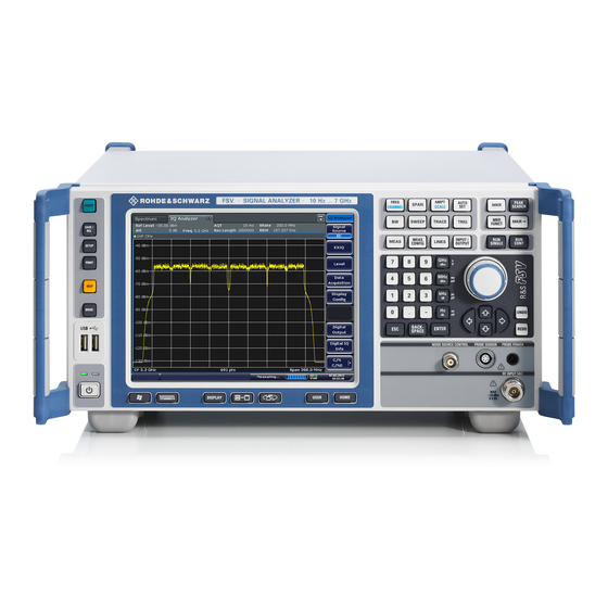
This chapter describes the front panel, including all function keys and connectors. Figure 3-1 shows the front panel view of the R&S FSVA. (The R&S FSV is very similar.) The individual elements are described in more detail in the subsequent sections. - Page 31 ® Front and Rear Panel View R&S FSVA/FSV Front Panel View Description Auxiliary functions to display Win- Chapter 3.1.1, "Function Keys on the Front dows Start menu or on-screen key- Panel", on page 17 board Display options for screen Chapter 6.4, "Changing the Display",...
- Page 32 ® Front and Rear Panel View R&S FSVA/FSV Front Panel View 3.1.1 Function Keys on the Front Panel A detailed description of the corresponding menus and the other function keys is provided in chapter 6 "Instrument Functions" of the Operating Manual.
- Page 33 Sets the reference level, the displayed dynamic range, the RF attenuation and the unit for the level display. (SCALE) Sets the level offset and the input impedance. Activates the preamplifier (option RF Preamplifier, R&S FSV- B22). (SCALE for special applications) AUTO SET Enables automatic settings for level, frequency or sweep type mode.
- Page 34 Noise marker (Noise Meas) ● Phase noise ● n dB down function ● AM/FM audio demodulation (with option R&S FSV-B3) ● Peak list MKR-> Used for search functions of the measurement markers (maxi- mum/minimum of the trace). Assigns the marker frequency to the center frequency, and the marker level to the reference level.
- Page 35 The screen is touch-sensitive, offer- ing an alternative means of user interaction for quick and easy handling of the device. Figure 3-2 shows the touchscreen display of the R&S FSVA/FSV. The indi- vidual elements are described in more detail in Chapter 6, "Basic Operations", on page 65.
- Page 36 3.1.3 Connectors on the Front Panel This section describes the front connectors and interfaces of the R&S FSVA/FSV. Optional connectors and interfaces are indicated by the option name in brackets. Most connectors on the front panel (except for USB) are located at the bottom right-hand side.
- Page 37 3.1.3.4 PROBE POWER The R&S FSVA/FSV provides a connector for supply voltages of +15 V to -12 V and ground for active probes and preamplifiers. A maximum current of 140 mA is available. This connector is suitable as power sup- ply for high-impedance probes from Agilent.
- Page 38 External mixers can be connected at the LO OUT/IF IN and IF IN female connec- tors (option R&S FSV-B21 for R&S FSVA/FSV 30 and R&S FSVA/FSV 40 instru- ments). Both two-port and three-port mixers can be used. Connect the mixer as follows: Quick Start Guide 1321.3066.02 ─...
- Page 39 LO OUT / IF IN and IF IN with the SMA caps supplied. Three-port mixer 1. Connect the LO OUT / IF IN output of the R&S FSVA/FSV to the LO port of the external mixer. 2. Connect the IF IN input of the R&S FSVA/FSV to the IF port of the external mixer.
-
Page 40: Rear Panel View
Rear Panel View Two-port mixer 1. 1. Connect the LO OUT / IF IN output of the R&S FSVA/FSV to the LO/IF port of the external mixer. The nominal LO level is 15.5 dBm. Because of the diplexer contained in the R&S FSVA/FSV, the IF signal can be tapped from the line which is used to feed the LO signal to the mixer. - Page 41 ® Front and Rear Panel View R&S FSVA/FSV Rear Panel View Figure 3-3: Rear panel view = LAN = TRIGGER OUTPUT = IF/VIDEO = USB = AUX PORT 6+7 = External generator control (option B10) = EXT TRIGGER / GATE IN...
- Page 42 (see data sheet). 3.2.1.2 The LAN interface can be used to connect the R&S FSVA/FSV to a local network for remote control, printouts and data transfer. The assignment of the RJ-45 con- nector supports twisted-pair category 5 UTP/STP cables in a star configuration (UTP stands for unshielded twisted pair, and STP for shielded twisted pair).
- Page 43 ® Front and Rear Panel View R&S FSVA/FSV Rear Panel View 3.2.1.6 REF OUT This connector can be used to provide an external reference signal (e.g. the OCXO or ultra high precision reference signal) to other devices that are connec- ted to this instrument.
- Page 44 ® Front and Rear Panel View R&S FSVA/FSV Rear Panel View EMI impact on measurement results Electromagnetic interference (EMI) can affect the measurement results. To avoid any impact, make sure that the following conditions are met: ● Use suitable double-shielded cables.
- Page 45 Ultra High Precision Reference Option (R&S FSV-B14) Alternatively to the OCXO reference, an ultra high precision reference (option R&S FSV-B14) is available. This option generates an even more precise 10 MHz reference signal with an output level of ≥ 0 dBm. If instal- led, and if no external signal is used, this signal is used as an internal refer- ence (also if an OCXO reference is installed).
- Page 46 3.2.2.3 Digital Baseband Interface (R&S FSV-B17) The R&S FSVA/FSV Digital Baseband Interface option (R&S FSV-B17) provides an online digital I/Q data interface on the rear panel of the instrument for input and output. The digital input and output can be enabled in the base unit or in one of the applications (where available).
-
Page 47: Preparing For Use
Putting into Operation This section describes the basic steps to be taken when setting up the R&S FSVA/FSV for the first time. Risk of injury due to disregarding safety information Observe the information on appropriate operating conditions provided in the data sheet to prevent personal injury or damage to the instrument. - Page 48 ® Preparing for Use R&S FSVA/FSV Putting into Operation Risk of instrument damage due to inappropriate operating conditions An unsuitable operating site or test setup can damage the instrument and connected devices. Before switching on the instrument, observe the infor- mation on appropriate operating conditions provided in the data sheet.
- Page 49 The instrument comes with the following accessories: ● Power cable ● Quick Start Guide 4.1.3 Placing or Mounting the Instrument The R&S FSVA/FSV is designed for use under laboratory conditions, either on a bench top or in a rack. Quick Start Guide 1321.3066.02 ─ 06...
- Page 50 Putting into Operation Bench Top Operation If the R&S FSVA/FSV is operated on a bench top, the surface should be flat. The instrument can be used in horizontal position, standing on its feet, or with the sup- port feet on the bottom extended.
- Page 51 ● If the instruments have foldable feet, fold them in completely. Rackmounting The R&S FSVA/FSV can be installed in a rack using a rack adapter kit (for the order no., see data sheet). The installation instructions are part of the adapter kit.
- Page 52 Connecting the AC Power The R&S FSVA/FSV is equipped with an AC power supply connector. The R&S FSVA/FSV can be used with different AC power voltages and adapts itself automatically to it. Refer to the datasheet for the requirements of voltage and fre- quency.
- Page 53 When only DC power is available, for example from a battery or in a vehicle, an optional DC power supply adapter (R&S FSV-B30) can be connected to the R&S FSVA/FSV to operate the instrument with a DC voltage of 10 V to 28 V. For installation instructions see the option's installation guide.
- Page 54 Putting into Operation Switching the DC power supply off 1. Press the ON/OFF key on the front panel of the R&S FSVA/FSV and wait until the instrument has shut down. 2. Switch off the power switch on the rear panel of the R&S FSVA/FSV.
- Page 55 Preparing for Use R&S FSVA/FSV Putting into Operation 2. Switch off the power switch on the rear panel of the R&S FSVA/FSV. 3. Switch off the DC power supply. 4. Switch off the battery pack. 4.1.7.1 Charging the Battery Pack The battery pack is not charged in the factory.
- Page 56 FSVA/FSV Putting into Operation 4. Insert the rechargeable batteries into the charging slots of the charger. ‑ B34 charger Figure 4-2: R&S FSVA/FSV LEDs indicate the operating state of each charging slot: ● Charging Green LED flashes ● Charging completed Green LED remains lit ●...
- Page 57 4.1.8 Switching the Instrument On and Off Switching the instrument on If an optional DC power supply (R&S FSV-B30) or an optional battery pack (R&S FSV-B32) is used, you must switch on these devices first; see Chap- ter 4.1.6, "Using an Optional DC Power Supply",...
- Page 58 ® Preparing for Use R&S FSVA/FSV Putting into Operation 4.1.9 Performing a Self Alignment and a Self Test Operating temperature Before performing this functional test, make sure that the instrument has reached its operating temperature (for details, refer to the data sheet).
-
Page 59: Connecting Usb Devices
For an overview of the available options, refer to the datasheet. Connecting USB Devices The USB interfaces of the R&S FSVA/FSV allow you to connect USB devices directly to the instrument. Increase the number of possible connections using USB hubs. Due to the large number of available USB devices, there is almost no limit to the expansions that are possible with the R&S FSVA/FSV. - Page 60 R&S FSVA/FSV Connecting USB Devices When a USB device is then disconnected from the R&S FSVA/FSV, Windows immediately detects the change in hardware configuration and deactivates the corresponding driver. All USB devices can be connected to or disconnected from the instrument during operation.
-
Page 61: Connecting An External Monitor
If the external monitor is selected, the R&S FSVA/FSV display is disabled. The screen content (measurement screen) formerly displayed on the R&S FSVA/FSV is displayed on the external screen. If you select both moni- tors, the R&S FSVA/FSV screen and the external screen are both active. - Page 62 Printers..............54 4.4.1 Changing the Language of the Instrument Interface You can change the language of the R&S FSVA/FSV graphical user interface (softkeys, dialog boxes, input settings etc.) to the any other installed language, if available. If you do not understand the currently used interface language, this may be difficult.
- Page 63 ® Preparing for Use R&S FSVA/FSV R&S FSVA/FSV Setup 2. Press the "Reference Int/Ext" softkey until it is in the desired state. External reference signal It is important that the external reference signal is deactivated when switch- ing from external to internal reference to avoid interactions with the internal reference signal.
- Page 64 If the touchscreen is so out of order that you cannot navigate properly, con- nect an external mouse to the R&S FSVA/FSV and follow the steps descri- bed below to start re-alignment.
- Page 65 ® Preparing for Use R&S FSVA/FSV R&S FSVA/FSV Setup 4. Using a finger or any other pointing device, press the 4 markers on the screen. The touchscreen is aligned according to the executed pointing operations. 4.4.5 Setting the Screen Colors To change the colors of the displayed objects, two default color settings are provi- ded.
- Page 66 ® Preparing for Use R&S FSVA/FSV R&S FSVA/FSV Setup viewed from above or below. In the instrument's default setting, "Default Col- ors 1" is active. Remote commands: DISP:CMAP:DEF1 DISP:CMAP:DEF2 4.4.5.3 Using the Predefined Color Set 1. In the screen colors submenu (see Chapter 4.4.5.1, "Displaying the Screen...
- Page 67 ® Preparing for Use R&S FSVA/FSV R&S FSVA/FSV Setup 6. Repeat the steps for all objects that you want to change in color. 7. To change to user-defined colors, press the "Userdefined Colors" softkey. For details refer toChapter 4.4.5.4, "Defining and Using a User-Defined Color Set",...
- Page 68 4.4.6 Setting the Display Power Save Function The R&S FSVA/FSV provides a feature for automatically switching off its screen after a user-defined period of time. The background lighting is disabled if no entries are made from the front panel after the selected response time (key, soft- key and rotary knob).
- Page 69 ® Preparing for Use R&S FSVA/FSV R&S FSVA/FSV Setup Deactivating Display Power Save ► In the "Display Setup" submenu, press the "Display Pwr Save On/Off" softkey again. "Off" is highlighted and the power save mode is switched off. 4.4.7 Selecting and Configuring Printers You can printout your measurement results using a local printer or a network printer.
- Page 70 Preparing for Use R&S FSVA/FSV R&S FSVA/FSV Setup ● To save the hardcopy in an image file, select one of the image types. Depending on the image type, the color depth varies (e.g. 4-bit for BMP, 24-bit for PNG and JPEG).
-
Page 71: Windows Operating System
After the R&S FSVA/FSV is started, the operating system boots and the instrument firm- ware is started automatically. - Page 72 ® Preparing for Use R&S FSVA/FSV Windows Operating System Risk of rendering instrument unusable The instrument is equipped with the Windows 10 operating system. You can install additional software on the instrument, however, additional soft- ware can impair instrument function. Thus, run only programs that Rohde &...
- Page 73 For the administrator account, an automatic login function is active by default. If activated, login is carried out automatically for the administrator (with full access) in the background when the R&S FSVA/FSV is started, without having to enter a password. This function is active until you explicitly deactivate it or change the password.
- Page 74 1. Press the "Windows" key or the CTRL + ESC key combination on your key- board to access the operating system of the R&S FSVA/FSV (see also Chap- ter 4.5.4, "Accessing the Start Menu",...
- Page 75 3. Save the changes to the file. Reactivating the automatic login function 1. Press the "Windows" key or the CTRL + ESC key combination on your key- board to access the operating system of the R&S FSVA/FSV (see also Chap- ter 4.5.4, "Accessing the Start Menu",...
- Page 76 ® Preparing for Use R&S FSVA/FSV Windows Operating System All necessary system settings can be defined in the "Start > Settings" menu (for required settings refer to the Windows 10 documentation and to the hardware description). Quick Start Guide 1321.3066.02 ─ 06...
-
Page 77: Firmware Update And Installation Of Firmware Options
® Firmware Update and Installation of Firmware Options R&S FSVA/FSV Firmware Update Firmware Update and Installation of Firmware Options This chapter describes how to update the firmware and how to activate optional firmware packages. Updating the firmware or installing optional firmware requires administrator rights (see Chapter 4.5.3,... -
Page 78: Activating Firmware Options
® Firmware Update and Installation of Firmware Options R&S FSVA/FSV Activating Firmware Options 6. Press "Execute" The installation program will guide you through the installation. 7. After the firmware update, the "UNCAL" status display indicates the necessity of a self alignment. Perform a self alignment (for details refer to Chapter 4.1.9,... - Page 79 7. Reboot the instrument. With time-limited licenses, a message box appears if an option is about to expire. Press the "OK" button to resume using the R&S FSVA/FSV. If an option has already expired, a message box appears for you to confirm. In this case, all instrument functions are unavailable (including remote control) until the R&S FSVA/FSV is rebooted.
-
Page 80: Basic Operations
Information in the Diagram Area Basic Operations This chapter gives an overview on how to work with the R&S FSVA/FSV. It describes what kind of information is displayed in the diagram area, how to oper- ate the R&S FSVA/FSV via the front panel keys and other interaction methods, and how to use the Online Help. - Page 81 6.1.1 Channel Display Using the R&S FSVA/FSV you can handle several different measurement tasks (channels) at the same time (although they can only be performed asynchro- nously). For each channel, a separate tab is displayed on the screen. In order to switch from one channel display to another, simply press the corresponding tab.
- Page 82 (with a finger or mouse pointer). The cor- responding (edit) dialog box is displayed where you can edit the setting. In spectrum mode, the R&S FSVA/FSV shows the following settings: Ref Level Reference level m.+el.Att...
- Page 83 Acquisition time; for ACP/CCDF measurements, IQ analyzer and option R&S FSV-K7 Demodulation bandwidth option R&S FSV-K7 only Dig Out State of digital output, option R&S FSV-B17 only 6.1.3 Measurement Settings Information In addition to the common hardware settings, the channel bar above the diagram...
- Page 84 A frequency offset ≠ 0 Hz is set. DC/AC An external DC or AC calibration signal is in use. Input source: digital I/Q (option R&S FSV-B17 only) 6.1.4 Diagram-specific and Trace Information Diagram-specific information, e.g. concerning traces, is indicated in the diagram header and footer.
- Page 85 ® Basic Operations R&S FSVA/FSV Information in the Diagram Area MIN PEAK detector SAMPLE detector AVERAGE detector RMS detector QUASIPEAK detector CISPR Average detector RMS Average detector Trace Mode Sweep mode: Clrw CLEAR/WRITE MAX HOLD MIN HOLD AVERAGE (Lin/Log/Pwr) View...
- Page 86 ® Basic Operations R&S FSVA/FSV Information in the Diagram Area Marker Information in Marker Table In addition to the marker information displayed within the diagram grid, a separate marker table may be displayed beneath the diagram. This table provides the fol-...
- Page 87 ® Basic Operations R&S FSVA/FSV Information in the Diagram Area Hiding the status bar You can hide the status bar display, e.g. in order to enlarge the display area for the measurement results. 1. Press the DISPLAY key. 2. In the "Display Settings" dialog box, select "Status Bar State: Off".
-
Page 88: Means Of User Interaction
Instrument was set to an external reference but no signal was detected on the reference input. OVEN OCXO reference frequency (option R&S FSV-B4) has not yet reached its operating temperature. The message usually disappears a few minutes after power has beeen switched on. - Page 89 ® Basic Operations R&S FSVA/FSV Means of User Interaction For most tasks, there are at least 2 alternative methods to perform them: ● Using the touchscreen ● Using other elements provided by the front panel, e.g. the keypad, rotary knob, or arrow and position keys 6.2.1...
- Page 90 ® Basic Operations R&S FSVA/FSV Means of User Interaction Table 6-1: Standard Application Functions in the Toolbar Icon Description Opens the "Select Mode" menu (see Chapter 6.1.1, "Channel Display", on page 66) Opens an existing measurement (settings) file Stores the current measurement file...
- Page 91 ® Basic Operations R&S FSVA/FSV Means of User Interaction Deactivating and Activating the Touchscreen Function The touchscreen function can be deactivated, e.g. when the instrument is being used for demonstration purposes and tapping the screen should not provoke an action.
- Page 92 ® Basic Operations R&S FSVA/FSV Means of User Interaction You can use the TAB key on the on-screen keyboard to move the focus from one field to another in dialog boxes. 6.2.4 Keypad The keypad is used to enter alphanumeric parameters. It contains the following keys: ●...
- Page 93 ® Basic Operations R&S FSVA/FSV Means of User Interaction – If no input field is currently active, the most recently entered value is undone, i.e. the previous value is retrieved. Thus, you can toggle between two values (e.g. spans). ● ENTER key –...
- Page 94 ® Basic Operations R&S FSVA/FSV Means of User Interaction UPARROW/DNARROW keys The UPARROW or DNARROW keys do the following: ● In a numeric edit dialog box, increase or decrease the instrument parameter. ● In a list, scroll forward and backward through the list entries.
- Page 95 ® Basic Operations R&S FSVA/FSV Means of User Interaction (For details on function keys in general see Chapter 3.1.1, "Function Keys on the Front Panel", on page 17.) A list of softkeys for a certain function key is also called a menu. Each softkey can either represent a specific function, or a submenu that in turn represents several softkeys.
- Page 96 ® Basic Operations R&S FSVA/FSV Means of User Interaction Some softkeys belong to a certain (firmware) option. If this option is not imple- mented in your device, the associated softkeys are not displayed. Hiding softkeys You can hide the softkey display, e.g. when using remote control, in order to enlarge the display area for the measurement results.
- Page 97 6.2.9 Dialog Boxes In most cases, the R&S FSVA/FSV dialog boxes are designed to enter a numeric value. In the documentation, these dialog boxes are called "edit dialog boxes". Dialog boxes that are not only designed for parameter entry have a more complex structure and, in the documentation, are called "dialog boxes".
-
Page 98: Setting Parameters
® Basic Operations R&S FSVA/FSV Setting Parameters Figure 6-2: Edit dialog box for parameter entry The title bar shows the name of the parameter that was selected. The entry is performed in the editing line. When the dialog box is displayed, the focus is on the editing line and it contains the currently used parameter value and its unit. - Page 99 ® Basic Operations R&S FSVA/FSV Setting Parameters 6.3.2 Entering Alphanumeric Parameters If a field requires alphanumeric input, you can use the on-screen keyboard to enter numbers and (special) characters (see also Chapter 6.2.3, "On-screen Key- board", on page 76). Figure 6-3: On-screen keyboard Alternatively, you can use the keypad.
- Page 100 ® Basic Operations R&S FSVA/FSV Setting Parameters Correcting an entry: 1. Using the arrow keys, move the cursor to the right of the entry you want to delete. 2. Press the BACKSPACE key. 3. The entry to the left of the cursor is deleted.
- Page 101 ® Basic Operations R&S FSVA/FSV Setting Parameters 6.3.3 Navigating in Dialog Boxes Some of the dialog boxes are not only for parameter entry, and therefore have a more complex structure. The following figure shows an example. Changing the focus The focus on the graphical user interface is moved by pressing an element on the screen, or via the rotary knob.
- Page 102 ® Basic Operations R&S FSVA/FSV Setting Parameters Figure 6-4: Focused area Figure 6-5: Focused area in edit mode Edit mode When using the touchscreen for focus changes, all focused areas are in the edit mode automatically, if available. Otherwise, you must switch to edit mode manually.
- Page 103 ® Basic Operations R&S FSVA/FSV Setting Parameters Chapter 6.3.2, "Entering Alphanumeric Parameters", on page 84. If you edit fields, the edit mode is activated automatically when you start typing. ● To move the focus to the next interface element (e.g. field, option, list), press it on the screen, or turn the rotary knob.
-
Page 104: Changing The Display
In some cases, e.g. if you want to install a printer, original Windows dialog boxes are used. In these dialog boxes, the navigation behavior is different to the one you are used to from R&S FSVA/FSV applications. In the following, the important differences and useful tips are listed: ●... - Page 105 When working with an external monitor or operating via remote control on a com- puter, it is useful to be able to interact with the R&S FSVA/FSV without requiring the keypad and keys located on the front panel of the instrument. Therefore, a "Soft Front Panel"...
- Page 106 ® Basic Operations R&S FSVA/FSV Changing the Display Using the F6 key you can toggle the Front Panel display on and off. Remote: SYST:DISP:FPAN:STAT ON Working with the Soft Front Panel Basic operation with the soft Front Panel is identical to normal operation. To acti- vate a key, either press the key on the touchscreen, or click on it with the mouse pointer.
- Page 107 ® Basic Operations R&S FSVA/FSV Changing the Display 2. In the "Display Settings" dialog box, select "Mini Front Panel State: On". The "Mini Front Panel" window appears on the screen. It can be moved any- where on the screen where it does not interfere with your current task.
- Page 108 ® Basic Operations R&S FSVA/FSV Changing the Display 6.4.4 Enlarging the Display Area You can enlarge the screen display area if you are using an external monitor or the Soft and Mini Soft Frontpanel display (see Chapter 6.4.3, "Soft and Mini Soft Front Panel Display",...
- Page 109 ® Basic Operations R&S FSVA/FSV Changing the Display Zoom and the number of sweep points Note that zooming is merely a visual tool, it does not change any measure- ment settings, such as the number of sweep points! You should increase the number of sweep points before zooming, as other- wise the function has no real effect (see the "Sweep Points"...
- Page 110 ® Basic Operations R&S FSVA/FSV Changing the Display Scrolling in the zoomed display You can scroll the diagram area to display the entire diagram using the scrollbars at the right and at the bottom of the diagram. To return to selection mode in the diagram While you are in zoom mode, touching the screen changes the zoom area.
- Page 111 ® Basic Operations R&S FSVA/FSV Changing the Display DISP:ZOOM:AREA 5,30,20,100 3. Hide the overview window: DISP:ZOOM:OVER OFF 6.4.7 Adding a Title to the Diagram Header You can add an introductory title to the trace information in the diagram header. 1. Press the SETUP key.
- Page 112 ® Basic Operations R&S FSVA/FSV Changing the Display 3. Press the "More" softkey. 4. Press the "Theme Selection" softkey. A list of available themes is displayed. 5. Select the desired theme from the list. The screen display changes according to the selected theme.
- Page 113 ® Basic Operations R&S FSVA/FSV Changing the Display To descrease the display update rate 1. Press the DISPLAY key. The "Display Settings" dialog box is opened. 2. Under "Display Update Rate", select "Slow". The display is updated less frequently, and performance for measurements should improve.
-
Page 114: Basic Measurement Examples
Measuring a Sinusoidal Signal Basic Measurement Examples The following measurement examples are intended as an introduction to operat- ing the R&S FSVA/FSV. The User Manual contains additional and more advanced examples. Refer to chapter "Advanced Measurement Examples" to find the following topics: ●... - Page 115 The R&S FSVA/FSV always displays its amplitude and fre- quency at the marker position. The frequency measurement uncertainty is deter- mined by the frequency reference of the R&S FSVA/FSV, the resolution of the marker frequency display and the number of sweep points.
- Page 116 ® Basic Measurement Examples R&S FSVA/FSV Measuring a Sinusoidal Signal M1[1] -30.00 dBm 128.00000 MHz The field header indicates the number of the marker (Marker 1) and the trace on which the marker is located ([1] = Trace 1). Note: Performing a peak search. When a marker is initially activated, it auto- matically performs the peak search function (as shown in the example).
- Page 117 Low Reference Levels If the selected reference level is lower than the highest signal that occurs in the spectrum, the signal path in the R&S FSVA/FSV is overloaded. In this case, the message "IFOVL" is displayed in the error message field.
- Page 118 The built-in frequency counter allows you to measure the frequency more accu- rately than measuring it with the marker. The frequency sweep is stopped at the marker, and the R&S FSVA/FSV measures the frequency of the signal at the marker position.
-
Page 119: Measuring Harmonics Of Sinusoidal Signals
® Basic Measurement Examples R&S FSVA/FSV Measuring Harmonics of Sinusoidal Signals Figure 7-1: Measurement of the frequency with the frequency counter Prerequisites for using the internal frequency counter In order to obtain a correct result when measuring the frequency with the internal frequency counter, an RF sinusoidal signal or a spectral line must be available. - Page 120 Press the "Start" softkey and enter 100 MHz. c) Press the "Stop" softkey and enter 400 MHz. The R&S FSVA/FSV displays the fundamental and the first and second harmonics of the input signal. 3. To average (smooth) the noise, reduce the video bandwidth.
- Page 121 ® Basic Measurement Examples R&S FSVA/FSV Measuring Harmonics of Sinusoidal Signals Figure 7-2: Measuring the harmonic suppression of the internal reference generator. Delta markers D2 [1] and D3 [1] show the offset of the first and second harmonics from the fundamental.
- Page 122 ® Basic Measurement Examples R&S FSVA/FSV Measuring Harmonics of Sinusoidal Signals Reducing the noise by reducing the video bandwidth 1. Press the BW key. 2. Press the "Video BW Manual" softkey. 3. Reduce the video bandwidth to 1 kHz (for example), by entering 1 kHz.
-
Page 123: Measuring Signal Spectra With Multiple Signals
® Basic Measurement Examples R&S FSVA/FSV Measuring Signal Spectra with Multiple Signals 2. Press the "Trace Wizard" softkey. 3. For "Trace 1", press the button in the "Trace Mode" column and select "Aver- age" from the list. The noise component of the trace is smoothed by averaging 10 successive traces. - Page 124 128,03 MHz 1. Set the signal analyzer to the default state by pressing the PRESET key. The R&S FSVA/FSV is set to its default state. 2. Set the center frequency to 128.015 MHz and the frequency span to 300 kHz.
- Page 125 Matching generator and R&S FSVA/FSV frequencies The level drop is located exactly in the center of the screen only if the genera- tor frequencies match the frequency display of the R&S FSVA/FSV exactly. To achieve exact matching, the frequencies of the generators and the R&S FSVA/FSV must be synchronized.
- Page 126 ® Basic Measurement Examples R&S FSVA/FSV Measuring Signal Spectra with Multiple Signals 4. Set the resolution bandwidth to 100 kHz. To do so, in the bandwidth menu, press the "Res BW Manual" softkey and enter 100 kHz. It is no longer possible to clearly distinguish the two generator signals.
- Page 127 Since the dynamic range of a signal analyzer is very large, extremely small modulation depths can also be measured precisely. For this purpose, the R&S FSVA/FSV provides measure- ment routines that output the modulation depth numerically in % directly.
- Page 128 Press the "More" key. c) Press the "AM Mod Depth" softkey. The R&S FSVA/FSV automatically sets a marker to the carrier signal in the center of the diagram and one delta marker each to the upper and lower AM sidebands. The R&S FSVA/FSV calculates the AM modulation depth from the level differences of the delta markers to the main marker and out- puts the numeric value in the marker field.
- Page 129 50 % AM, 1 kHz AF 1. Set the signal analyzer to the default state by pressing the PRESET key. The R&S FSVA/FSV is set to its default state. 2. Set the center frequency to 128 MHz and the span to 0 Hz.
-
Page 130: Measurements In Zero Span
Press the "Trg/Gate Level" softkey and enter 50%. The trigger level is displayed as a horizontal line across the entire mea- surement diagram. The R&S FSVA/FSV displays the 1 kHz AF signal as a static image in zero span. Use a headset to listen to the AF. - Page 131 Press the SPAN key and enter 0 Hz, or press the "Zero Span" softkey. 3. Set the reference level of the R&S FSVA/FSV to 10 dBm (= level of the signal generator +10 dB) and set the attenuation to 20 dB.
- Page 132 Measuring the Edges of a GSM Burst with High Time Resolution Because of the high time resolution of the R&S FSVA/FSV at the 0 Hz display range, the edges of TDMA bursts can be measured precisely. The edges can be shifted to the screen area by using the trigger offset.
- Page 133 ® Basic Measurement Examples R&S FSVA/FSV Measurements in Zero Span Table 7-6: Signal generator settings (e.g. R&S SMU) Frequency 890 MHz Level 0 dBm Modulation GSM, one timeslot activated The measurement is based on the setting in the example above for measuring the power of the GSM during the activation phase.
- Page 134 -50 µs. The R&S FSVA/FSV displays the rising edge of the GSM burst. Figure 7-9: Rising edge of the GSM burst displayed with high time resolution 4.
- Page 135 For this purpose, the R&S FSVA/FSV provides the function for measuring abso- lute and relative power in zero span. In the following example, the measurement is performed using a GSM burst.
- Page 136 Press the BW key. d) Press the "Res BW Manual" softkey and enter 1 MHz. 3. Set the reference level of the R&S FSVA/FSV to 0 dBm (= level of the signal generator) by pressing the AMPT key and entering 0 dBm.
- Page 137 Using the rotary knob, move the second vertical line to the end of the burst. The R&S FSVA/FSV displays the power during the activation phase of the burst. Figure 7-11: Power measurement during the activation phase of the burst 7.
- Page 138 Measurements in Zero Span b) Switch the "Trg/Gate Polarity" softkey to "Neg." The R&S FSVA/FSV initiates triggering in response to the falling edge of the burst. This shifts the burst to the left-hand half of the measurement dia- gram. The power is measured in the deactivation phase. The start of the burst is shifted to the center of the screen and the power during the deacti- vation phase is measured.
- Page 139 1 kHz AF 1. Set the signal analyzer to the default state by pressing the PRESET key. The R&S FSVA/FSV is set to its default state. 2. Set the center frequency to 127.50 MHz and the span to 300 kHz.
- Page 140 Figure 7-13: Display of the filter edge of the 300 kHz filter as an FM discriminator characteristic 5. Set the FM deviation to 50 kHz on the signal generator. 6. Set the span to 0 Hz on the R&S FSVA/FSV. a) Press the SPAN key. b) Press the "Zero Span" softkey.
- Page 141 ® Basic Measurement Examples R&S FSVA/FSV Measurements in Zero Span c) Press the "Trg/Gate Level" softkey and enter 50%. A static image for the FM AF signal is produced. Result: (-10 ( 5) dB; this yields a deviation of 100 kHz when the steepness of the demodulator characteristic is 5 dB/100 kHz.
-
Page 142: Storing And Loading Instrument Settings
Storing and Loading Instrument Settings Storing and Loading Instrument Settings The R&S FSVA/FSV can store complete instrument settings together with instru- ment configurations and measurement data in a settings file. The data is stored on the built-in hard disk or - if selected - on a USB device (e.g. memory stick) or on a network drive. - Page 143 ® Basic Measurement Examples R&S FSVA/FSV Storing and Loading Instrument Settings The name may contain letters and digits. For details on alphanumeric entries Chapter 6.3.2, "Entering Alphanumeric Parameters", on page 84. 4. To store the file in a directory different to the default directory, select the required path in the Files area.
- Page 144 7.5.4 Configuring Automatic Loading If the R&S FSVA/FSV is switched on in the factory default state, it loads the instrument settings that it had when switched off (provided that it was switched off using the ON / OFF key on the front panel; see Chapter 4.1.8, "Switching the...
-
Page 145: Controlling The R&S Fsva/Fsv Remotely
Operation with Windows Remote Desktop Controlling the R&S FSVA/FSV Remotely In addition to working with the R&S FSVA/FSV interactively, located directly at the instrument, it is also possible to operate and control it from a remote PC. Various methods for remote control are supported: ●... - Page 146 3. Search for "remote access". 4. Select "Allow remote access to your computer". 5. Define which users are to be given access to the R&S FSVA/FSV via Remote Desktop. Note: The user account under which configuration is carried out is automati- cally enabled for Remote Desktop.
- Page 147 Chap- ter 8.8.2, "Creating Users", on page 176. c) Select "OK" to confirm the settings. 6. The R&S FSVA/FSV is now ready for connection setup with the Remote Desktop program of the controller. 8.1.2 Configuring the Controller Remote Desktop Client The Windows Remote Desktop Client is part of the operating system and can be accessed via "Start >...
- Page 148 7. Open the "Local Resources" tab for enabling printers, local drives and serial interfaces. 8. If you will need to access drives of the controller from the R&S FSVA/FSV (e.g. in order to store settings or to copy files from the controller to the R&S FSVA/FSV), select "More", then enable the "Drives"...
- Page 149 10. Open the "Display" tab. The options for configuring the R&S FSVA/FSV screen display are displayed. 11. Under "Remote desktop size", you can set the size of the R&S FSVA/FSV window on the desktop of the controller. 12. Under "Colors", do not change the settings.
- Page 150 13. Set the "Display the connection bar when I use the full screen" option: ● If activated, a bar showing the network address of the R&S FSVA/FSV will appear at the top edge of the screen. You can use this bar to reduce, mini- mize or close the window.
- Page 151 FSVA/FSV Operation with Windows Remote Desktop If a dark screen appears or a dark square appears in the upper left-hand cor- ner of the screen, you must restart the R&S FSVA/FSV in order to see the modified screen resolution. ●...
-
Page 152: Operation With A Vnc Client
8.1.4 Deactivating the R&S FSVA/FSV via Remote Operation 1. Click the R&S FSVA/FSV soft front panel and close the application with the key combination ALT + F4. 2. Click the desktop and press the key combination ALT + F4 to shut down the R&S FSVA/FSV. - Page 153 ● The complete mini soft front panel is available on the client ("Alt-M" opens the mini soft front panel). All R&S FSVA/FSV instruments as of firmware version 3.0 support a VNC and are delivered with a version of the TightVNC software. On the client side, you can use a web browser or a VNC client to access the instrument.
-
Page 154: Brief Introduction To Remote Control
® Controlling the R&S FSVA/FSV Remotely R&S FSVA/FSV Brief Introduction to Remote Control Brief Introduction to Remote Control The instrument can be remote-controlled via the network (LAN interface). For details on configuring the LAN interface see Chapter 8.6, "Setting Up a Network (LAN) Connection",... - Page 155 ® Controlling the R&S FSVA/FSV Remotely R&S FSVA/FSV Brief Introduction to Remote Control 8.3.1.1 Linking the Remote Control Library for Visual Basic Programming notes: ● Outputting text using the print function Using the print method, this example displays the value of the variable MyVar in the "Immediate"...
- Page 156 ® Controlling the R&S FSVA/FSV Remotely R&S FSVA/FSV Brief Introduction to Remote Control Since the DLL returns zero-terminated strings in responses, a string of suffi- cient length must be created before the functions InstrRead() and ilrd() are called, because Visual Basic inserts a length specification in front of the strings and this specification is not updated by the DLL.
- Page 157 ® Controlling the R&S FSVA/FSV Remotely R&S FSVA/FSV Brief Introduction to Remote Control ErrorMessage = "" If (status < 0) Then 'Query the error message from VISA If (viStatusDesc(vi, status, ErrorMessage) = VI_SUCCESS) Then Err.Description = ErrorMessage End If Err.Raise (status)
- Page 158 ® Controlling the R&S FSVA/FSV Remotely R&S FSVA/FSV Brief Introduction to Remote Control 'If the network provides a name resolution mechanism, the hostname of 'the instrument can be used instead of the numeric IP address 'the resource string for GPIB would be "GPIB::20::INSTR'' status = viOpen(defaultRM, "TCPIP::10.0.0.10::INSTR'', 0, 1000, analyzer)
- Page 159 ® Controlling the R&S FSVA/FSV Remotely R&S FSVA/FSV Brief Introduction to Remote Control Configuring the Power Save Function for the Display During remote control operation, it is often unnecessary to display the measure- ment results on screen. Although the command SYSTem:DISPlay:UPDate...
- Page 160 ® Controlling the R&S FSVA/FSV Remotely R&S FSVA/FSV Brief Introduction to Remote Control 8.3.1.5 Reading Out Instrument Settings The settings made above can now be read out. To do so, the abbreviated com- mands are used. REM --------- Reading out instrument settings ------------------------------...
- Page 161 ® Controlling the R&S FSVA/FSV Remotely R&S FSVA/FSV Brief Introduction to Remote Control END SUB REM ************************************************************************ 8.3.1.7 Command Synchronization The synchronization methods used in the following example are described in the Operating Manual, chapter "Remote Control - Basics", section "Command Sequence and Command Synchronization".
- Page 162 8.3.2.1 Default Setting of the R&S FSVA/FSV The following settings provide typical examples of how to change the default set- ting of the R&S FSVA/FSV. Note that only some of the settings are necessary depending on the application example.
- Page 163 'Disable questionable Statusreg End Sub REM ************************************************************************ Default Settings for Measurements REM ************************************************************************ Public Sub SetupInstrument() '--------- Default setting f the R&S FSV --------------------------------- CALL SetupStatusReg 'Configure status registers CALL InstrWrite(analyzer,"*RST") 'Reset instrument CALL InstrWrite(analyzer,"SYST:DISP:UPD ON") 'ON: screen display on 'OFF: off (improved performance) CALL InstrWrite(analyzer,"INIT:CONT OFF")
- Page 164 ® Controlling the R&S FSVA/FSV Remotely R&S FSVA/FSV Brief Introduction to Remote Control CALL InstrWrite(analyzer,"INP:ATT 10dB") 'Input attenuation '--------- Level scaling --------------------------------------------------- CALL InstrWrite(analyzer,"DISP:WIND:TRAC:Y:SPAC LOG") 'Log level axis CALL InstrWrite(analyzer,"DISP:WIND:TRAC:Y:SCAL 100dB") 'Level range CALL InstrWrite(analyzer,"DISP:WIND:TRAC:Y:SCAL:MODE ABS") 'Absolute scaling CALL InstrWrite(analyzer,"CALC:UNIT:POW DBM") 'y meas.
- Page 165 ® Controlling the R&S FSVA/FSV Remotely R&S FSVA/FSV Brief Introduction to Remote Control 'Video bandwidth CALL InstrWrite(analyzer,"SWE:TIME 100ms") 'Sweep time END SUB 8.3.2.2 Using Markers and Delta Markers The markers are used for marking points on traces, reading out measurement results and for selecting a display area quickly.
- Page 166 ® Controlling the R&S FSVA/FSV Remotely R&S FSVA/FSV Brief Introduction to Remote Control 'set to peak and then to next peak left CALL InstrWrite(analyzer,"CALC:DELT2:X?;Y?") 'Read delta marker 2 frequency and level result$ = Space$(100) CALL InstrRead(analyzer, result$, 100, retCount) Debug.Print "Delta 2: ";result$ '--------- Peak search with search range limit in x direction -------------- CALL InstrWrite(analyzer,"CALC:MARK:X:SLIM:STAT ON;LEFT _...
- Page 167 In this case, it may be necessary to suppress the carrier by using a notch filter in order to prevent the RF input of the R&S FSVA/FSV from being overloaded.
- Page 168 First, a high reference level is used on the carrier frequency, and then a low reference level is used on the frequency of the third harmonic. The default setting of the R&S FSVA/FSV for measurements ("SetupInstrument") is also used as a starting point here, after which adaptations for the measurement are carried out.
- Page 169 Two markers are used to determine both the noise and the phase noise at a 10 kHz offset from the carrier signal. REM ************************************************************************ Public Sub Noise() Dim retCount as Long '--------- Default setting of the R&S FSV -------------------------------- CALL SetupStatusReg 'Configure status register CALL InstrWrite(analyzer,"*RST") 'Reset instrument CALL InstrWrite(analyzer,"INIT:CONT OFF")
- Page 170 ® Controlling the R&S FSVA/FSV Remotely R&S FSVA/FSV Brief Introduction to Remote Control CALL InstrRead(analyzer, result$, 100, retCount) Debug.Print "Phase Noise [dBc/Hz]: "; result$ '--------- Measuring the noise -------------------------------------------- CALL InstrWrite(analyzer,"CALC:MARK:X 99.96MHz") 'Position marker 1 CALL InstrWrite(analyzer,"CALC:MARK:FUNC:NOIS:RES?") 'Query and output result...
- Page 171 FSVA/FSV Brief Introduction to Remote Control Array dimensions The arrays for the measured data are dimensioned so they provide suffi- cient space for trace data of the R&S FSVA/FSV (691 measurement points). REM ************************************************************************ Public Sub ReadTrace() '--------- Creating variables ----------------------------------------------...
- Page 172 'This subroutine selects the settings to be stored and creates the 'data record "TEST1" in the directory C:\R_S\Instr\user. It uses the default 'setting and resets the instrument after the setting is stored. '--------- Default settings of the R&S FSV ------------------------------ CALL SetupInstrument CALL InstrWrite(analyzer,"INIT:CONT OFF") 'Change to single sweep CALL InstrWrite(analyzer,"INIT;*WAI")
- Page 173 REM ************************************************************************ Setting the Data Record for Startup Recall In the following example, the first step is to change the R&S FSVA/FSV to the default state. In the next step, the TEST1 data record stored under C:\R_S\Instr\user is selected for the startup recall function, i.e. the data record is then set after each *RST, presetting and each time the instrument is started.
- Page 174 'Create buffer for printer name FOR i = 0 TO 49 Devices$(i) = Space$(50) 'Preallocate buffer for printer name NEXT i '--------- Default setting of the R&S FSV ------------------------------- CALL SetupStatusReg 'Configure status register CALL InstrWrite(analyzer,"*RST") 'Reset instrument Quick Start Guide 1321.3066.02 ─ 06...
- Page 175 ® Controlling the R&S FSVA/FSV Remotely R&S FSVA/FSV Brief Introduction to Remote Control CALL InstrWrite(analyzer,"INIT:CONT OFF") 'Single sweep mode CALL InstrWrite(analyzer,"SYST:DISP:UPD ON") 'Screen display on '--------- Measurement settings ------------------------------------------ CALL InstrWrite(analyzer,"FREQ:CENT 100MHz;SPAN 10MHz") 'Frequency setting CALL InstrWrite(analyzer,"DISP:TRAC:Y:RLEV -10dBm") 'Reference level CALL InstrWrite(analyzer,"INIT;*WAI")
-
Page 176: Remote Control Interfaces And Protocols
® Controlling the R&S FSVA/FSV Remotely R&S FSVA/FSV Remote Control Interfaces and Protocols CALL InstrWrite(analyzer,"HCOP;*OPC") 'Start printout SRQWaitTimeout = 5000 'Allow 5s for completion 'Now wait for the service request statusSRQ = viWaitOnEvent(vi, VI_EVENT_SERVICE_REQ, SRQWaitTimeout, _ eventType, eventVi) CALL viClose(eventVi) - Page 177 ® Controlling the R&S FSVA/FSV Remotely R&S FSVA/FSV Remote Control Interfaces and Protocols Table 8-1: Remote control interfaces and protocols Inter- Remarks Protocols, VISA address string face ● Local The interface is based on HiSLIP High-Speed LAN Instrument Protocol Area TCP/IP and supports vari- (IVI-6.1)
- Page 178 ® Controlling the R&S FSVA/FSV Remotely R&S FSVA/FSV Remote Control Interfaces and Protocols – inst0 selects the VXI-11 protocol (default) – hislip0 selects the newer HiSLIP protocol ● INSTR indicates the instrument resource class (optional) Example: ● Instrument has the IP address 192.1.2.3; the valid resource string using VXI-11 protocol is: TCPIP::192.1.2.3::INSTR...
-
Page 179: Configuring The Gpib Interface
A GPIB interface is integrated on the rear panel of the instrument. You can set the GPIB address and the ID response string. The GPIB language is set as SCPI by default and cannot be changed for the R&S FSVA/FSV. For details on the GPIB interface see Chapter 3.2.1.7, "GPIB... -
Page 180: Setting Up A Network (Lan) Connection
Windows operating system, or with LXI (LAN eXtension for Instruments). The R&S FSVA/FSV is equipped with a network interface and can be connected to an Ethernet LAN (local area network). Provided the network administrator has... - Page 181 You must assign an IP address to the instrument and the computer, see Chapter 8.6.2, "Assigning the IP Address", on page 167. Note: As the R&S FSVA/FSV uses a 1 GBit LAN, a crossover cable is not necessary (due to Auto-MDI(X) functionality). Quick Start Guide 1321.3066.02 ─ 06...
- Page 182 ® Controlling the R&S FSVA/FSV Remotely R&S FSVA/FSV Setting Up a Network (LAN) Connection Risk of network failure Consult your network administrator before performing the following tasks: ● Connecting the instrument to the network ● Configuring the network ● Changing IP addresses ●...
- Page 183 ® Controlling the R&S FSVA/FSV Remotely R&S FSVA/FSV Setting Up a Network (LAN) Connection Risk of network errors Connection errors can affect the entire network. If your network does not support DHCP, or if you choose to disable dynamic TCP/IP configuration, you must assign valid address information before connecting the instrument to the LAN.
- Page 184 7. Confirm the displayed message ("Yes" button) to restart the instrument. Using a DNS server to determine the IP address If a DNS server is configured on the R&S FSVA/FSV, the server can determine the current IP address for the connection using the permanent computer name.
- Page 185 ® Controlling the R&S FSVA/FSV Remotely R&S FSVA/FSV Setting Up a Network (LAN) Connection 5. Tap the entry named "Internet Protocol Version 4 (TCP/IPv4)" to highlight it. 6. Select the "Properties" button. 7. On the "General" tab, select "Use the following DNS server addresses" and enter your own DNS addresses.
- Page 186 ® Controlling the R&S FSVA/FSV Remotely R&S FSVA/FSV Setting Up a Network (LAN) Connection Each instrument is delivered with an assigned computer name, but this name can be changed. The default instrument name is a non-case-sensitive string with the following syn- tax: <Type><variant>-<serial_number>...
-
Page 187: How To Configure The Lan Using The Lxi Web Browser Interface
® Controlling the R&S FSVA/FSV Remotely R&S FSVA/FSV How to Configure the LAN Using the LXI Web Browser Interface How to Configure the LAN Using the LXI Web Browser Interface The instrument's LXI browser interface works correctly with all W3C compliant browsers. - Page 188 ► Press the "Device Indicator" button on the "Instrument Home Page" to activate or deactivate the LXI status icon on the status bar of the R&S FSVA/FSV. A green LXI status symbol indicates that a LAN connection has been estab- lished;...
- Page 189 ® Controlling the R&S FSVA/FSV Remotely R&S FSVA/FSV How to Configure the LAN Using the LXI Web Browser Interface mode uses DHCP server or Dynamic Link Local Addressing (Automatic IP) to obtain the instrument IP address. Changing the LAN configuration is password-protected. The default pass- word is LxiWebIfc (notice upper and lower case characters).
-
Page 190: Configuring The Network
® Controlling the R&S FSVA/FSV Remotely R&S FSVA/FSV Configuring the Network 3. Select "Submit". Configuring the Network After network support has been installed, data can be exchanged between the instrument and other computers, and network printers can be used. Network operation is only possible if you are authorized to access network resources. - Page 191 ® Controlling the R&S FSVA/FSV Remotely R&S FSVA/FSV Configuring the Network the interruption of the network connection and does not set up the connection when the instrument is switched on. If you are not prompted to enter the user name and password, see Chap- ter 4.5.3.1, "Automatic Login...
- Page 192 Windows and on the network. 8.8.4 Mapping Network Drives 1. Press the SAVE/ RCL key on the front panel of the R&S FSVA/FSV. 2. Press the "File Manager" softkey. 3. Press the "More" softkey. 4. Press the "Network Drive" softkey.
- Page 193 The drive is displayed in the Explorer. Note: Only networks that you authorized to access are connected. Disconnecting network drives 1. Press the SAVE/ RCL key on the front panel of the R&S FSVA/FSV. 2. Press the "File Manager" softkey. 3. Press the "More" softkey.
- Page 194 ® Controlling the R&S FSVA/FSV Remotely R&S FSVA/FSV Configuring the Network 8.8.5 Sharing Directories (only with Microsoft Networks) Sharing directories makes data available for other users. This is only possible in Microsoft networks. Sharing is a property of a file or directory.
-
Page 195: Index
® Index R&S FSVA/FSV Index Symbols LAN ............. 27 MONITOR (VGA) ........ 27 75 Ω (enhancement label) ....... 69 Noise source control ......21 OCXO ..........30 Power Sensor ........22 AC supply fuse ........37 Probe power ........22 Administrator rights ......... - Page 196 ® Index R&S FSVA/FSV Electrostatic discharge ......33 IFOVL (status display) ......73 Enhancement labels ........ 68 Interfaces Entry LAN ........... 162 Canceling ..........77 IP address ..........162 Concluding .......... 77 Changing .......... 167 Error messages IP configuration see User Manual .........72 LXI ............
- Page 197 ® Index R&S FSVA/FSV Offset (hardware setting) ......67 Browser interface ......172 On-screen keyboard ........ 76 LAN configuration ......173 Online help Ping ...........174 Working with ......... 7 Operating system ........56 Login ........... 58 service packs ........57 MAXH (trace information) ......
- Page 198 ® Index R&S FSVA/FSV Reference frequency Softkeys OCXO ..........30 Firmware Update ........ 62 Ultra high precision (option B14) ..30 More ............80 Release notes ......... 14 Up ............80 Remote control SPLIT/MAXIMIZE Command synchronization ....146 Key ............89 Configuration ........130 Stand-alone operation ......
- Page 199 ® Index R&S FSVA/FSV Update rate Display ..........97 Updates ........... 62 Connector ........... 28 User account ........... 62 VBW (hardware setting) ......67 Virus protection ........57 VISA ............162 Resource string .........162 VNC ............137 VXI protocol ........... 163 Web browser Configuration interface ......172...
Need help?
Do you have a question about the FSV and is the answer not in the manual?
Questions and answers