Table of Contents
Advertisement
Advertisement
Chapters
Table of Contents

Related Manuals for Phoenix Contact CAPAROC Series


Summary of Contents for Phoenix Contact CAPAROC Series
- Page 1 CAPAROC: System and installation User manual...
- Page 2 User manual CAPAROC: System and installation UM EN CAPAROC, Revision 01 2021-10-19 This manual is valid for: All modules of the CAPAROC system. PHOENIX CONTACT GmbH & Co. KG • Flachsmarktstraße 8 • 32825 Blomberg • Germany phoenixcontact.com...
-
Page 3: Table Of Contents
Mounting distances ..................... 27 Connecting or removing cables ....................29 Connecting cables....................29 Connecting the power supply ................29 5.2.1 Requirements for the power supply ............. 29 5.2.2 Connecting the power supply ............... 30 Removing cables....................30 3 / 66 109745_en_01 PHOENIX CONTACT... - Page 4 Performing the update ..................56 After use ..........................59 Device replacement..................... 59 Device defect and repair..................59 Maintenance......................59 Decommissioning and disposal ................60 Appendix for document lists...................... 61 List of figures ....................... 61 List of tables ......................63 4 / 66 PHOENIX CONTACT 109745_en_01...
-
Page 5: For Your Safety
– Qualified application programmers and software engineers. The users must be familiar with the relevant safety concepts of automation technology as well as applicable stan- dards and other regulations. 5 / 66 109745_en_01 PHOENIX CONTACT... -
Page 6: Field Of Application Of The Product
Product changes Modifications to the device hardware are not permitted. Modifications to the firmware are only permitted by means of firmware updates provided by Phoenix Contact. Incorrect operation or modifications to the device can endanger your safety or damage the device. -
Page 7: The Caparoc Product Family
The customizable standard, thanks to a wide range of possible combinations of the fu- ture-proof modular system – Easy operation for everyone through tool-free assembly, uninterrupted installation, and transparent operating state – Strikingly simple design-in with extensive support from the selection up to digital ser- vices 7 / 66 109745_en_01 PHOENIX CONTACT... -
Page 8: Structure Of The Caparoc System
CAPAROC modules are snapped on. Figure 2-1 Example of a CAPAROC system DIN rail End bracket Power module 2-channel 2 - 10 A circuit breaker 1-channel 1 - 10 A circuit breaker Potential distribution module Current rail 8 / 66 PHOENIX CONTACT 109745_en_01... -
Page 9: Approvals
Go to the page for the relevant product. • Switch to the “Approvals” tab. The current approvals for the product are listed. Observe any notes and restrictions for the approvals in the module-specific packing slip or in the module-specific documentation. 9 / 66 109745_en_01 PHOENIX CONTACT... -
Page 10: Overview Of The Caparoc Modules
CAPAROC PM PN 1110986 power module for supplying the system with the required voltage and PROFINET interface. The system provides extended diagnos- tics and control options via the integrated interface. 10 / 66 PHOENIX CONTACT 109745_en_01... -
Page 11: Caparoc Circuit Breaker Modules
2 A nominal current CAPAROC E1 12-24DC/4A 1157285 4 A nominal current CAPAROC E1 12-24DC/6A 1157286 6 A nominal current CAPAROC E1 12-24DC/8A 1157279 8 A nominal current CAPAROC E1 12-24DC/10A 1157284 10 A nominal current 11 / 66 109745_en_01 PHOENIX CONTACT... -
Page 12: Caparoc Current Rails
8 HP (49.2 mm). CAPAROC CR EXT20 1115674 Rear current rail for extending the system and distributing the sup- ply voltage with an overall width of 20 HP (123 mm). 12 / 66 PHOENIX CONTACT 109745_en_01... -
Page 13: Housing Versions, Design, And Dimensions
4-channel circuit breaker CAPAROC E4 12-24DC/1-10A Figure 2-14 on Figure 2-15 on page 18 page 18 PD 0V 0 V potential distributor CAPAROC PD 0V Figure 2-16 on Figure 2-17 on page 19 page 19 13 / 66 109745_en_01 PHOENIX CONTACT... -
Page 14: Design Of Caparoc Pm Pn
CAPAROC system CAPAROC PM PN power module Figure 2-6 Design of CAPAROC PM PN Power LED (PWR) Diagnostic LEDs RJ45 connections Release Feed-in IN+, IN- Figure 2-7 Dimensional drawing of CAPAROC PM PN 24,8 111,3 14 / 66 PHOENIX CONTACT 109745_en_01... -
Page 15: Design Of Caparoc Pm S-R
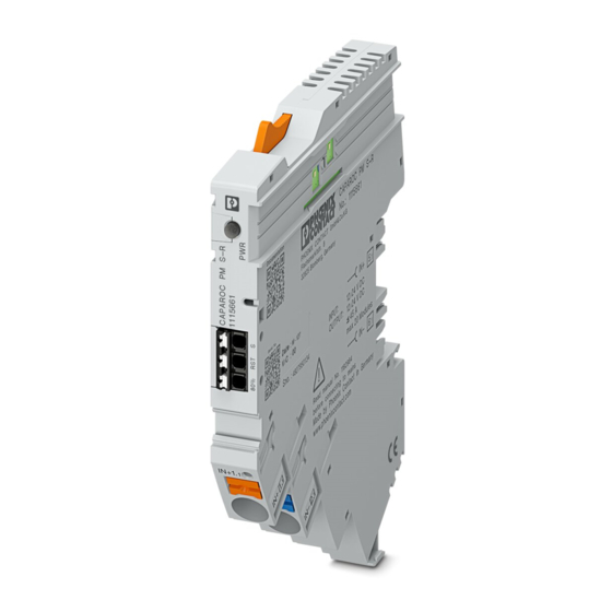
The CAPAROC product family CAPAROC PM S-R power module Figure 2-8 Design of CAPAROC PM S-R Power LED (PWR) Feed-in IN+, IN- Signal connections Release Figure 2-9 Dimensional drawing of CAPAROC PM S-R 12,4 111,3 15 / 66 109745_en_01 PHOENIX CONTACT... -
Page 16: Design Of Caparoc E1
CAPAROC system CAPAROC E1 ... circuit breaker Figure 2-10 Design of CAPAROC E1 ... LED button channel 1 Release Load output channel 1 Figure 2-11 Dimensional drawing of CAPAROC E1 ... 111,3 16 / 66 PHOENIX CONTACT 109745_en_01... -
Page 17: Design Of Caparoc E2
LED button channel 1 Load output channel 1 Rotary switch channel 1 Load output channel 2 LED button channel 2 Release Rotary switch channel 2 Figure 2-13 Dimensional drawing of CAPAROC E2 ... 12,4 111,3 17 / 66 109745_en_01 PHOENIX CONTACT... -
Page 18: Design Of Caparoc E4
LED button channel 2 Load output channel 3 LED button channel 3 Load output channel 4 LED button channel 4 Release Load output channel 1 Figure 2-15 Dimensional drawing of CAPAROC E4 ... 12,4 111,3 18 / 66 PHOENIX CONTACT 109745_en_01... -
Page 19: Design Of Caparoc Pd 0V
The CAPAROC product family CAPAROC PD 0V potential distributor Figure 2-16 Design of CAPAROC PD 0V IN- potential distribution Release Figure 2-17 Dimensional drawing of CAPAROC PD 0V 109,9 19 / 66 109745_en_01 PHOENIX CONTACT... - Page 20 CAPAROC system 20 / 66 PHOENIX CONTACT 109745_en_01...
-
Page 21: Transport And Unpacking
Read the complete packing slip carefully before unpacking the device. slip • Retain the packing slip. Checking the delivery • Check the delivery for damage and completeness. • Submit claims for any transport damage immediately. 21 / 66 109745_en_01 PHOENIX CONTACT... - Page 22 CAPAROC system 22 / 66 PHOENIX CONTACT 109745_en_01...
-
Page 23: Mounting And Removing Modules
See Section “Qualification of users” on page 23 / 66 109745_en_01 PHOENIX CONTACT... -
Page 24: Basic Information About Mounting
For the maximum number, please refer to the table below and the relevant power module data sheet. Table 4-1 Maximum number of circuit breaker modules Power module Description Max. number CAPAROC PM S-R power module with status-reset 20 modules CAPAROC PM PN power module with PROFINET 16 modules 24 / 66 PHOENIX CONTACT 109745_en_01... -
Page 25: Mounting The Modules
Make sure that the device plugs for the current rail are posi- tioned above the corresponding opening on the current rail. Use the guide slots on the hous- ing sides to connect the modules together. Figure 4-2 Snapping on the modules 25 / 66 109745_en_01 PHOENIX CONTACT... -
Page 26: Removing The Modules
Only the internal bus system is interrupt- ed. After successfully mounting a new identical module, communication is automati- cally restored and the system does not need to be restarted. 26 / 66 PHOENIX CONTACT 109745_en_01... -
Page 27: Mounting Distances
Leave enough space below the system to connect all the cables. Maintain a minimum distance of 30 mm above and below to ensure adequate convec- tion cooling. Figure 4-4 Mounting distances for the CAPAROC system 27 / 66 109745_en_01 PHOENIX CONTACT... - Page 28 CAPAROC system 28 / 66 PHOENIX CONTACT 109745_en_01...
-
Page 29: Connecting Or Removing Cables
EN 50178 and EN 64010-2-201. They prevent short circuits between the primary and secondary circuit. WARNING: Dangerous contact voltage in the event of ground faults – The CAPAROC modules for the low-voltage area must only be operated in ground- ed networks. 29 / 66 109745_en_01 PHOENIX CONTACT... -
Page 30: Connecting The Power Supply
To remove a cable from the terminal point, press on the spring lever using a suitable tool (e.g., bladed screwdriver with a blade width of 2.5 mm). This opens the leg-spring connection of the relevant terminal point. • Remove the conductor. 30 / 66 PHOENIX CONTACT 109745_en_01... -
Page 31: Startup
Signaling (LED) Description LED off Channel switched off Green Channel switched on Yellow Channel switched on, channel load >80% of the set nominal current. Check the configuration. Flashing Channel is in programming mode 31 / 66 109745_en_01 PHOENIX CONTACT... -
Page 32: Programming (2-Channel Circuit Breakers)
• Turn the rotary switch back up one position. • Press the channel LED button for >2 seconds to save the new current value. 32 / 66 PHOENIX CONTACT 109745_en_01... -
Page 33: 2-Channel Visual Signaling
The previous value has been set again once the LED only flashes red. Yellow/red Flashing Channel is in overload mode and will be switched off in approx. 5 seconds. Check the configuration. 33 / 66 109745_en_01 PHOENIX CONTACT... -
Page 34: Connecting Loads
Visual signaling of the power module status-reset (PM S-R) Description Designation Color Meaning State Green/yel- Voltage indicator Green on Operating voltage present low/red Red on Operating voltage outside the nominal voltage range Operating voltage not present 34 / 66 PHOENIX CONTACT 109745_en_01... -
Page 35: Indicators On The Protective Device
(1- and 4-channel circuit breakers)” on page 31 Section “Programming (2- channel circuit breakers)” on page 6.3.3 Flow chart for startup The flow chart illustrates typical startup. It does not include all the parameterization options. 35 / 66 109745_en_01 PHOENIX CONTACT... - Page 36 Slot 0, Subslot 2: Strom-Parametriersperre Einzelkanal Einstellung Strom-Parametriersperre abgeschlossen Sperrung aller Taster Slot 0, Subslot 2: am System notwendig? Lokale Benutzerinterface-Sperre nein Einstellung Lokale Benutzerinterface-Sperre abgeschlossen Konfiguration der IP Parameter im Engineering Vergabe des Profinet Namens Ende 36 / 66 PHOENIX CONTACT 109745_en_01...
-
Page 37: Process, Parameter, And Diagnostic Data
4 ... 7 Reserved * The permissible total current of the system depends on the temperature derating ** The value range that can be represented does not correspond to the permissible operating voltage range 37 / 66 109745_en_01 PHOENIX CONTACT... -
Page 38: Output Process Data Slot 0/Subslot 2 (Global System Data)
The reset command switches all channels that were shut down by a short circuit or overload back on. The command is issued once by setting bit “0” to “1”. To send another reset com- mand, first set bit 0 to “0”. Then set bit 0 to “1” again. 38 / 66 PHOENIX CONTACT 109745_en_01... -
Page 39: Input Process Data Of Caparoc E1 12-24Dc/1-10A
1500 ms. Internally, only one validity flag is available per module. The rest of the output process data for this module is also deemed valid as soon as either of the two flags is set to “1”. 39 / 66 109745_en_01 PHOENIX CONTACT... -
Page 40: Input Process Data Of Caparoc E2 12-24Dc/2-10A
1 = hardware is defective 5 ... 7 Reserved Byte 0 ... 7 Set nominal current, channel 2 {1 ... 10} A Byte 0 ... 7 Flowing current, channel 2 0 ... 255 (= 0 ... 25.5 A) 40 / 66 PHOENIX CONTACT 109745_en_01... -
Page 41: Output Process Data Of Caparoc E2 12-24Dc/2-10A
1500 ms. Internally, only one validity flag is available per module. The rest of the output process data for this module is also deemed valid as soon as either of the two flags is set to “1”. 41 / 66 109745_en_01 PHOENIX CONTACT... -
Page 42: Input Process Data Of Caparoc E4 12-24Dc/1-10A
1 = hardware is defective 5 ... 7 Reserved Byte 0 ... 7 Set nominal current, channel 2 {1 ... 10} A Byte 0 ... 7 Flowing current, channel 2 0 ... 255 (= 0 ... 25.5 A) 42 / 66 PHOENIX CONTACT 109745_en_01... - Page 43 1 = hardware is defective 5 ... 7 Reserved Byte 0 ... 7 Set nominal current, channel 4 {1 ... 10} A Byte 0 ... 7 Flowing current, channel 4 0 ... 255 (= 0 ... 25.5 A) 43 / 66 109745_en_01 PHOENIX CONTACT...
-
Page 44: Output Process Data Of Caparoc E4 12-24Dc/1-10A
1500 ms. Internally, only one validity flag is available per module. The rest of the output process data for this module is also deemed valid as soon as either of the two flags is set to “1”. 44 / 66 PHOENIX CONTACT 109745_en_01... -
Page 45: Parameter And Diagnostic Data (Pdi Channel)
Table 7-10 Local user interface lock Byte Data Data Access Default setting offset type Byte 0 = lock inactive 1 = lock active 2 = no change 45 / 66 109745_en_01 PHOENIX CONTACT... -
Page 46: Global Switch-On Delay
PROFINET connection has been established. Table 7-12 Global operating mode Byte Data Data Access Default setting offset type Byte 0 = independent operation 1 = wait for fieldbus 2 = no change 46 / 66 PHOENIX CONTACT 109745_en_01... -
Page 47: Resetting The Application Parameters To Factory Default Settings
Table 7-13 Resetting the application parameters to factory default settings Byte Data Data Access Default setting offset type Byte 10 = reset power module 20 = reset power module and all circuit breaker modules 47 / 66 109745_en_01 PHOENIX CONTACT... -
Page 48: Parameters And Acyclic Data Slot 1
0 = no change {1 ... 10} = nominal current channel 4* * The nominal current is only adopted if the rotary switch is in the “RC” position (see Section , “CAPAROC E2 ... circuit breaker”) 48 / 66 PHOENIX CONTACT 109745_en_01... -
Page 49: Table 7-15 Local Nominal Current Programming Lock
2 = no change 0 = switch off channel 3 1 = switch on channel 3 2 = no change 0 = switch off channel 4 1 = switch on channel 4 2 = no change 49 / 66 109745_en_01 PHOENIX CONTACT... -
Page 50: Table 7-17 Error Counter
The counter to be reset must include a “0” in the byte. Example Clear error counter for channel 1 and retain error counter for channel 2: Table 7-18 Only clear error counter for channel 1 Byte Data Any number from 1 ... 255 50 / 66 PHOENIX CONTACT 109745_en_01... -
Page 51: Web Server
Following activation via PROFINET, it can be reached via port 80 using the previously as- signed IP address. The web server is used to monitor the system. It is only possible to set individual pa- rameters via PROFINET. 51 / 66 109745_en_01 PHOENIX CONTACT... - Page 52 CAPAROC system 52 / 66 PHOENIX CONTACT 109745_en_01...
-
Page 53: Updating The Caparoc Pm Pn Firmware
Web server Browser HTTP, Incom- area/inter- WebSock- ing/out- nal net- going work, de- pending on the routing rules Preparing the update • Start the PC WORX FIRMWARE UPDATER. • Click on “File...”. 53 / 66 109745_en_01 PHOENIX CONTACT... - Page 54 CAPAROC system Figure 8-1 PC WORX FIRMWARE UPDATER 54 / 66 PHOENIX CONTACT 109745_en_01...
- Page 55 Under “General, Time after which the device is available after update (ms)”, change the value to 120000 ms. Click “OK”. Figure 8-2 PC WORX FIRMWARE UPDATER, “Preferences” dialog Use the file with the extension “.bin” as the firmware file. 55 / 66 109745_en_01 PHOENIX CONTACT...
-
Page 56: Performing The Update
The device must have a valid IP address and subnet mask. • If necessary, enter a valid IP address or subnet mask in the corresponding field. • Start the scan again. Figure 8-4 PC WORX FIRMWARE UPDATER, device search 56 / 66 PHOENIX CONTACT 109745_en_01... - Page 57 The new firmware is installed, the yellow PWR LED on the device flashes. – As soon as the update is completed, the PWR LED lights up green. – The device is accessible again. Figure 8-6 PC WORX FIRMWARE UPDATER, complete update 57 / 66 109745_en_01 PHOENIX CONTACT...
- Page 58 If the update was successful, the device is highlighted in green. – The “Update Info” is “Ok”. Check that firmware “0.00.01” (test firmware) is displayed. This indicates definitively that the update was successful. Figure 8-7 PC WORX FIRMWARE UPDATER, successful update 58 / 66 PHOENIX CONTACT 109745_en_01...
-
Page 59: After Use
Device defect and repair Do not open the housing Repairs may only be carried out by Phoenix Contact. Do not open the housing. If the hous- ing is opened, the function of the device can no longer be ensured. Defective devices Please contact Phoenix Contact. -
Page 60: Decommissioning And Disposal
Packaging disposal Dispose of packaging materials that are no longer needed (cardboard packaging, paper, bubble wrap sheets, tubing, etc.) with household waste in accordance with the currently ap- plicable national regulations. 60 / 66 PHOENIX CONTACT 109745_en_01... -
Page 61: A Appendix For Document Lists
Figure 4-4: Mounting distances for the CAPAROC system ........27 Section 5 Figure 5-1: Connecting the CAPAROC power supply ........... 30 Section 6 Figure 6-1: Flow chart for initial startup of CAPAROC PROFINET ......36 61 / 66 109745_en_01 PHOENIX CONTACT... - Page 62 PC WORX FIRMWARE UPDATER, device search ......56 Figure 8-5: PC WORX FIRMWARE UPDATER, start update ........ 57 Figure 8-6: PC WORX FIRMWARE UPDATER, complete update ......57 Figure 8-7: PC WORX FIRMWARE UPDATER, successful update ...... 58 62 / 66 PHOENIX CONTACT 109745_en_01...
-
Page 63: A 2 List Of Tables
Table 7-10: Local user interface lock ..............45 Table 7-11: Global switch-on delay ................ 46 Table 7-12: Global operating mode ................ 46 Table 7-13: Resetting the application parameters to factory default settings ..47 63 / 66 109745_en_01 PHOENIX CONTACT... - Page 64 Local nominal current programming lock ..........49 Table 7-16: Channel outputs .................. 49 Table 7-17: Error counter..................50 Table 7-18: Only clear error counter for channel 1..........50 Section 8 Table 8-1: Interface to other systems..............53 64 / 66 PHOENIX CONTACT 109745_en_01...
- Page 65 The receipt of technical documentation (in particular user documentation) does not consti- tute any further duty on the part of Phoenix Contact to furnish information on modifications to products and/or technical documentation. You are responsible to verify the suitability and intended use of the products in your specific application, in particular with regard to observ- ing the applicable standards and regulations.
- Page 66 Should you have any suggestions or recommendations for improvement of the contents and layout of our manuals, please send your comments to: tecdoc@phoenixcontact.com 66 / 66 PHOENIX CONTACT GmbH & Co. KG • Flachsmarktstraße 8 • 32825 Blomberg • Germany phoenixcontact.com...
- Page 68 PHOENIX CONTACT GmbH & Co. KG Flachsmarktstraße 8 32825 Blomberg, Germany Phone: +49 5235 3-00 Fax: +49 5235 3-41200 E-mail: info@phoenixcontact.com phoenixcontact.com...
Need help?
Do you have a question about the CAPAROC Series and is the answer not in the manual?
Questions and answers