
Related Manuals for Phoenix Contact CBMC E4 24DC/1-10A IOL

Summary of Contents for Phoenix Contact CBMC E4 24DC/1-10A IOL
- Page 1 Multi-channel electronic device circuit breaker with IO-Link interface User manual...
-
Page 2: Cbmc E4
UM EN CBMC E4 ... IOL, revision 00 2017-08-31 This user manual is valid for: Designation Order No. CBMC E4 24DC/1-4A+ IOL 2910410 CBMC E4 24DC/1-10A IOL 2910411 PHOENIX CONTACT GmbH & Co. KG • Flachsmarktstraße 8 • 32825 Blomberg • Germany phoenixcontact.com... -
Page 3: Table Of Contents
About this document ........................7 Aim of this document .....................7 Hardware requirements ..................7 Description of the CBMC E4 24DC/1-4A+ IOL and CBMC E4 24DC/1-10A IOL ......9 General description of the device circuit breaker ...........9 Possible fields of application of the device circuit breaker ........10 Connection and operating elements ..............11... - Page 4 CBMC E4 ... IOL Appendixes..........................37 List of figures .......................37 List of tables ......................39 Index........................41 4 / 44 PHOENIX CONTACT 108147_en_00...
-
Page 5: For Your Safety
– Qualified application programmers and software engineers. The users must be familiar with the relevant safety concepts of automation technology as well as applicable stan- dards and other regulations. 5 / 44 108147_en_00 PHOENIX CONTACT... - Page 6 CBMC E4 ... IOL 6 / 44 PHOENIX CONTACT 108147_en_00...
-
Page 7: About This Document
About this document Aim of this document This user manual helps you to start up and operate the following products: – CBMC E4 24DC/1-4A+ IOL – CBMC E4 24DC/1-10A IOL Hardware requirements Table 2-1 Hardware requirements Hardware Description CBMC E4 ... IOL... - Page 8 CBMC E4 ... IOL 8 / 44 PHOENIX CONTACT 108147_en_00...
-
Page 9: Description Of The Cbmc E4 24Dc/1-4A+ Iol And Cbmc E4 24Dc/1-10A Iol
The CBMC Circuit Breaker Multichannel Compact CBMC E4 24DC/1-4A+ IOL and CBMC E4 24DC/1-10A IOL are identical in appearance. They only differ with regard to a function. In the following, the term device circuit breaker or CBMC E4 ... IOL is therefore generally used. -
Page 10: Possible Fields Of Application Of The Device Circuit Breaker
Output DC 24V 10 A Signal 29.5V L– SGnd Out 1 CBMC Out 2 1 -10 A > 100% Boost > 75% > 50% DC OK Input AC 100-240V N/- L/+ Figure 3-2 IO-Link with CBMC topology 10 / 44 PHOENIX CONTACT 108147_en_00... -
Page 11: Connection And Operating Elements
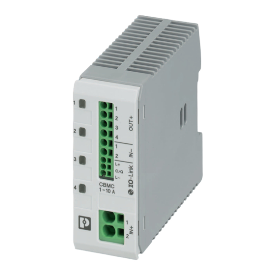
Description of the CBMC E4 24DC/1-4A+ IOL and CBMC E4 24DC/1-10A IOL Connection and operating elements CBMC Figure 3-3 CBMC E4 ... IOL operating elements Channel LED button Protected outputs 24 V DC supply IO-Link interface IO-Link LED 3.3.1 Channel LED button The channel LED button of the CBMC E4 ... -
Page 12: Diagnostics And Status Indicators
The LED flashes in the case of an active IO-Link connection with data ex- change between master and device. If you do not get any visual feedback via the LED, check the IO-Link connection and the IO-Link master configuration. 12 / 44 PHOENIX CONTACT 108147_en_00... -
Page 13: Operating Modes
Description of the CBMC E4 24DC/1-4A+ IOL and CBMC E4 24DC/1-10A IOL Operating modes 3.4.1 Independent operation The device can be operated without an IO-Link. For this, only the supply voltage and ground need to be connected. The channel states and the nominal currents can be adjusted via the buttons. - Page 14 CBMC E4 ... IOL 14 / 44 PHOENIX CONTACT 108147_en_00...
-
Page 15: Mounting And Power Supply
Maintain a minimum distance of 30 mm on the top and bottom to ensure convection cooling (see Figure 4-1 "Convection cooling"and Figure 4-2 "Minimum distance"). Figure 4-1 Convection cooling CBMC Figure 4-2 Minimum distance 15 / 44 108147_en_00 PHOENIX CONTACT... -
Page 16: Power Supply Connection
Table 4-2 Vendor and device ID Decimal Hexadecimal Vendor ID (Phoenix Contact) 00 B0 Device ID (CBMC E4 24DC/1-4A+ IOL) 393520 06 01 30 Device ID (CBMC E4 24DC/1-10A IOL) 393504 06 01 20 16 / 44 PHOENIX CONTACT 108147_en_00... -
Page 17: Process Data And Status Information
If an error in the power path is detected on a channel (see Section "Diagnostics and status indicators" on page 12), it is not possible to switch on the channel, either by button or via IO-Link. 17 / 44 108147_en_00 PHOENIX CONTACT... -
Page 18: Bit Assignment Of Data Type "Cbmc Io-Link To Master
Load current channel 1 Subindex Byte 4 PDin Load current channel 2 Subindex Byte 5 PDin Load current channel 3 Subindex Byte 6 PDin Load current channel 4 Subindex Byte 7 PDin Input voltage Subindex 18 / 44 PHOENIX CONTACT 108147_en_00... - Page 19 10 V and a gradient of 0.1 to a representable voltage range of 10.0 V ... 35.5 V. The process data is also available via acyclic access (see Section "Acyclic data" on page 20) 19 / 44 108147_en_00 PHOENIX CONTACT...
-
Page 20: Acyclic Data
22 bytes ro text Product name 22 bytes ro Product ID Order number 7 bytes Product text 52 bytes ro Serial number 10 bytes ro Hardware ver- 4 bytes sion Firmware version - 4 bytes 20 / 44 PHOENIX CONTACT 108147_en_00... - Page 21 0D00 reset Switching state OUT1-4 4 bytes 0; 1 OUT1 1 byte 0; 1 3329 OUT2 1 byte 0; 1 0D01 OUT3 1 byte 0; 1 OUT4 1 byte 0; 1 21 / 44 108147_en_00 PHOENIX CONTACT...
-
Page 22: Io-Link Specific Parameters
System command 128 The system command allows the controller of the CCBMC E4 ... IOL to be restarted. System command 130 The system command resets the device to its default settings. 22 / 44 PHOENIX CONTACT 108147_en_00... -
Page 23: Device-Specific Parameters
. By accessing Subindex 0, all four channel states can be read or written (if several channels are switched on via Subindex 0 access, the actual switching-on always happens sequentially with 100 ms delay). 23 / 44 108147_en_00 PHOENIX CONTACT... -
Page 24: Bit-Assignment Of Data Type "Channel State
Subindex 0 read access returns the byte sequence 01 00 00 00 . From this, it can be read that only channel 1 is currently switched on. The individual channel states of channels 1-4 are read- and writable under Subindex 1-4. 24 / 44 PHOENIX CONTACT 108147_en_00... -
Page 25: Bit-Assignment Of Data Type "Local Programming Lock
Bit 5 Bit 4 Bit 3 Bit 2 Bit 1 Bit 0 Nominal current channel 3 Byte 2 Bit 7 Bit 6 Bit 5 Bit 4 Bit 3 Bit 2 Bit 1 Bit 0 25 / 44 108147_en_00 PHOENIX CONTACT... -
Page 26: Error Memory
Error power path (MOSFET / Fail-safe element defective) channel 1 Error power path (MOSFET / Fail-safe element defective) channel 2 Error power path (MOSFET / Fail-safe element defective) channel 3 Error power path (MOSFET / Fail-safe element defective) channel 4 26 / 44 PHOENIX CONTACT 108147_en_00... -
Page 27: Bit-Assignment Of Data Type "Output Voltages
. The voltage value comes from multiplying the 16-bit value by a gradient of 0.1. This results in an output voltage of 29.9 V. The individual voltages of the channels are reached under Subindex 1-4. 27 / 44 108147_en_00 PHOENIX CONTACT... -
Page 28: Events
8CD0 36049 Surge voltage shutdown IN+ Warning Coming/Going Permitted maximum voltage ex- ceeded 8CD1 36056 Total current switch off OUT1 Warning Single event Total current switch off trigger: OUT1 carried maximum current 8CD8 28 / 44 PHOENIX CONTACT 108147_en_00... -
Page 29: Device Access Locks
The channel states are not data memory objects and can be changed either acyclically per index access or by means of process data outputs (PDout). 29 / 44 108147_en_00 PHOENIX CONTACT... - Page 30 CBMC E4 ... IOL 30 / 44 PHOENIX CONTACT 108147_en_00...
-
Page 31: A Technical Appendix
Altitude 2000 m Degree of protection IP20 General Flammability rating according to UL 94 Mounting type DIN rail: 35 mm Color Light gray RAL 7035 Protection class Pollution degree Design DIN rail module, one-piece 31 / 44 108147_en_00 PHOENIX CONTACT... - Page 32 45000 μF (depending on the current setting and the short- circuit current available) Vibration resistance, frequency 10 Hz ... 150 Hz (transmission frequency 58 Hz) Vibration resistance, acceleration 49 m/s² Vibration resistance test duration 150 min. (per axis and direction) 32 / 44 PHOENIX CONTACT 108147_en_00...
- Page 33 AWG conductor cross section 24 ... 12 Conductor cross section flexible, with ferrule, with plastic 0.25 mm² ... 1.5 mm² sleeve Conductor cross section flexible, with ferrule, w/o plastic 0.25 mm² ... 2.5 mm² sleeve 33 / 44 108147_en_00 PHOENIX CONTACT...
- Page 34 Conductor cross section flexible, with ferrule, with plastic 0.2 mm² ... 0.75 mm² sleeve Conductor cross section flexible, with ferrule, w/o plastic 0.25 mm² ... 1.5 mm² sleeve A 1.1 Derating T [°C] Figure A-2 Derating 34 / 44 PHOENIX CONTACT 108147_en_00...
-
Page 35: Ordering Data
With electronic locking of the set nominal currents. For installation on DIN rails. – Adjustable from 1 A to 4 A CBMC E4 24DC/1-4A+ IOL 2910410 – Adjustable from 1 A to 10 A CBMC E4 24DC/1-10A IOL 2910411 35 / 44 108147_en_00 PHOENIX CONTACT... - Page 36 8 IO-Link ports and 4 digital inputs, 24 V DC, M12 fast con- nection technology Network cable, Ethernet, CAT5 (100 Mbps), 4-pos., PUR, NBC-MSD/ 1,0-93E SCO 1407356 RAL 5021 (water blue), shielded, straight M12 SPEED- CON/IP67 plug (D-coding) to free cable end, cable length: 36 / 44 PHOENIX CONTACT 108147_en_00...
-
Page 37: B Appendixes
CBMC E4 ... IOL operating elements ..........11 Section 4 Figure 4-1: Convection cooling ................15 Figure 4-2: Minimum distance ................15 Appendix A Figure A-1: Dimensions ..................31 Figure A-2: Derating ....................34 Figure A-3: Tripping characteristics ...............35 37 / 44 108147_en_00 PHOENIX CONTACT... - Page 38 CBMC E4 ... IOL 38 / 44 PHOENIX CONTACT 108147_en_00...
-
Page 39: List Of Tables
Bit-assignment of data type "Local programming lock" ......25 Table 5-7: Bit-assignment of data type "Nominal current"........25 Table 5-8: Error memory ..................26 Table 5-9: Bit-assignment of data type "output voltages"........27 Table 5-10: Events....................28 Table 5-11: Device access locks ................29 39 / 44 108147_en_00 PHOENIX CONTACT... - Page 40 CBMC E4 ... IOL 40 / 44 PHOENIX CONTACT 108147_en_00...
-
Page 41: Index
O-Link connection ............16 Operating mode independent ............13 IO-Link..............13 Parameters Device-specific ............23 IO-Link-specific ............. 22 Power supply .............. 16 Programming lock ............25 Removal..............15 Status indicators ............12 System commands ............. 22 41 / 44 108147_en_00 PHOENIX CONTACT... - Page 42 CBMC E4 ... IOL 42 / 44 PHOENIX CONTACT 108147_en_00...
- Page 43 The receipt of technical documentation (in particular user documentation) does not constitute any further duty on the part of Phoenix Contact to furnish information on modifications to products and/or technical documentation. You are responsible to verify the suitability and intended use of the products in your specific application, in particular with regard to observing the applicable standards and regulations.
- Page 44 Should you have any suggestions or recommendations for improvement of the contents and layout of our manuals, please send your comments to: tecdoc@phoenixcontact.com 44 / 44 PHOENIX CONTACT GmbH & Co. KG • Flachsmarktstraße 8 • 32825 Blomberg • Germany phoenixcontact.com...
Need help?
Do you have a question about the CBMC E4 24DC/1-10A IOL and is the answer not in the manual?
Questions and answers