
Subscribe to Our Youtube Channel
Related Manuals for LeCroy WaveSurfer 400 Series


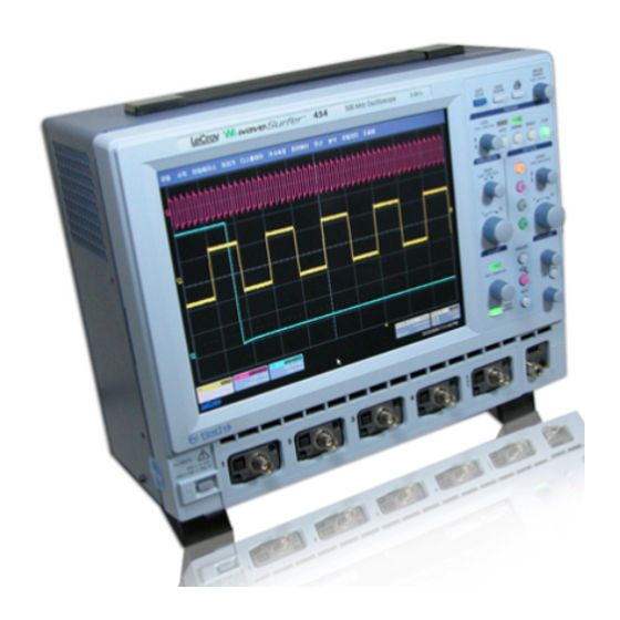
Summary of Contents for LeCroy WaveSurfer 400 Series
- Page 1 LeCroy Color Digital Oscilloscopes WaveSurfer 400 Series Service Manual Version A- September 2004 WAVESURFER-SM-E ECO 1...
- Page 2 © 2004 by LeCroy Corporation. All rights reserved. LeCroy, ActiveDSO, ProBus, SMART Trigger, WavePro, WaveRunner and WaveSurfer are registered trademarks of LeCroy Corporation. JitterTrack, WaveMaster, and X-Stream are trademarks of LeCroy Corporation. Information in this publication supersedes all earlier versions. Specifications subject to change without notice.
-
Page 3: Table Of Contents
Read this first Warranty Warranty and Product Support Product Assistance Maintenance Agreements Staying Up to Date Service and Repair How to return a Product What Comes with Your Scope General Information Product Assistance Installation for Safe and Efficient Operation Operating Environment Safety Symbols Power Requirements Cleaning and Maintenance... - Page 4 Theory of Operation System Block Diagram Main Board 4.2.1 Front End 4.2.2 Analog to Digital Converter 4.2.3 Trigger 4.2.4 Time Base 4.2.5 Calibrator 4-10 4.2.6 Scan DAC 4-10 4.2.7 Main Board Control 4-10 Computer 4-11 4.3.1 Operating System 4-11 4.3.2 Memory 4-11 4.3.3...
- Page 5 Theory of Operation 4.7.7 Control 4-21 4.7.7.1 Output Enable OUTPUT-EN/ (active low) 4-21 4.7.7.2 Line Frequency Synchronization Output Signal (LFS) 4-21 4.7.7.3 PWR_OK signal 4-21 4.7.8 Over-Current Protection 4-22 4.7.9 Over-Temperature Protection 4-22 4.7.10 Over-Voltage Protection 4-22 Theory of Operation - List of Figures Figure 4-1 WaveSurfer Block Diagram Figure 4-2...
- Page 6 Performance Verification Introduction 5.1.1 List of Tested Characteristics 5.1.2 Calibration Cycle Test Equipment Required 5.2.1 Test Records Turn On Input Impedance 5.4.1 Channel Input Impedance 5.4.2 External Trigger Input Impedance Leakage Current 5.5.1 Channel Leakage Current 5.5.2 External Trigger Leakage Current 5-12 Peak-Peak Noise Level 5-14...
- Page 7 Maintenance Introduction 6.1.1 Safety Precautions 6.1.2 Anti-static Precautions Software Update Procedure 6.3.1 Installing New X-Stream DSO Application Software 6.3.2 Software End User License Agreement 6.3.3 Installing Device Drivers 6.3.4 Restoring the Operating System 6.3.5 Software Options 6-12 6.3.5.1 Changing Software Option Key 6-12 Board Exchange Procedure 6-13...
- Page 8 Maintenance 6.10.2 Repair Level 6-45 6.10.3 Initial Troubleshooting 6-46 6.10.4 Power Supply Problem 6-48 6.10.5 No Display (Internal or External) 6-49 6.10.6 Internal Display Problem 6-51 6.10.7 Boot Up Sequence 6-52 6.10.8 Front Panel Controls or Touch Screen Does not Operate 6-53 6.10.9 Timebase Problem 6-57...
-
Page 9: Read This First
LeCroy authorized service center. However, this will be done only if the product is determined after examination by LeCroy to be defective due to workmanship or materials, and not to have been caused by misuse, neglect or accident, or by abnormal conditions or operation. -
Page 10: Staying Up To Date
Outside the warranty period, you will need to provide us with a purchase order number before we can repair your LeCroy product. You will be billed for parts and labor related to the repair work, and for shipping. -
Page 11: General Information
General Information Product Assistance Help on installation, calibration, and the use of LeCroy equipment is available from your local LeCroy office, or from LeCroy’s • Customer Care Center, 700 Chestnut Ridge Road, Chestnut Ridge, New York 10977–6499, U.S.A., tel. (845) 578–6020 •... - Page 12 The oscilloscope has not been designed to make direct measurements on the human body. Users who connect a LeCroy oscilloscope directly to a person do so at their own risk. 2-2 General Information...
-
Page 13: Power Requirements
Cleaning And Maintenance Maintenance and repairs should be carried out exclusively by a LeCroy technician Cleaning should be limited to the exterior of the instrument only, using a damp, soft cloth. Do not use chemicals or abrasive elements. Under no circumstances should moisture be allowed to penetrate the oscilloscope. - Page 14 This page intentionally left blank 2-4 General Information...
-
Page 15: Specifications
3. Specifications 3.1 Vertical WS424 WS422 WS434 WS432 WS454 WS452 Bandwidth (at probe tip) 200 MHz 350 MHz 500 MHz Rise Time (typical) 1.75 ns 1 ns 750 ps Input Channels Display 10.4" Color flat-panel TFT-LCD, 800x600 SVGA, touch screen Sample Rate (single-shot) 2 GS/s max (interleaved mode), 1 GS/s (all channels) Sample Rate (RIS mode) -
Page 16: Optional Smart Triggers
Standard 10/100Base-T Ethernet interface (RJ-45 connector). Connect to any network using DHCP with automatically assigned IP address. Remote Control Via LeCroy Remote Command Set (via Ethernet) USB Ports 3 USB ports (one on front of instrument) support Windows compatible devices... -
Page 17: Measure, Zoom, And Math Tools
3.6 Measure, Zoom, and Math Tools Standard Parameter Up to 6 of the following parameters can be calculated at one time on any Measurement waveform: Amplitude,Area, Base (Low), Delay, Duty, Fall Time (90%- 10%), Fall Time (80%-20%), Frequency,Maximum,Mean,Minimum,Overshoot+, Overshoot-, Period, Peak-Peak, Rise Time (10%-90%), Rise Time (20%-80%), RMS, Skew, Standard Deviation, Top (High), Width. -
Page 18: Environmental And Safety
3.10 Environmental and Safety Temperature (Operating) +5 °C to +40 °C Temperature (Non-Operating) –20 °C to +60 °C Humidity (Operating) 5% to 80% relative humidity (non-condensing) at <= 30 °C.Upper limit derates to 55% relative humidity (non-condensing) at +40 °C. Humidity (Non-Operating) 5% to 95% relative humidity (non-condensing) as tested per MIL–PRF–... -
Page 19: Theory Of Operation
Theory of Operation 4.1 System Block Diagram Figure 4-1 WaveSurfer Block Diagram Theory of Operation 4-1... -
Page 20: Main Board
Main Board The main board is divided into the following sections: • Front End Based on high impedance buffer, variable gain amplifier and differential amplifiers. • Analog to Digital Converter Based on the HAM631 and the relay switchyard to combine the input channels. •... -
Page 21: Front End
4.2.1 Front End The front end processes an analog signal for ADC and trigger, consists of 1M ohms attenuators, high impedance buffer, 200 ohms attenuator, variable gain amplifier SA5209D and differential amplifiers. The main functions of the Front end without the amplifiers are: •... - Page 22 Divide gain The gain ratio in each block and input range is a table below. At the BNC the dynamic range is 16 mV to 80V FS (full scale) and the output is 500 mV differential (HAD631 input). Range V/div Block 5mV 10mV 20mV 50mV 100mV 200mV 500mV ATT 1/*10...
-
Page 23: Analog To Digital Converter
SA5209D Differencial Variable gain amplifier Differencial amplifier Differencial amplifier 500mVpp full scale from Front End input to ADC system CHx SIG 20MHz & CHxa SIG 200MHz Bandwidth Limiter Bandwidth CHx GND *CHxa SIG Limiter Gain Offset Bandwidth limiter for Differencial amplifier DC calibration CHx GAIN CHx OS ADJ... -
Page 24: Trigger
Channel combine mode 4 channels mode (CH1 & CH3) 20RL1 CH1 ADC 20RL1 CH1 ADC CH1a SIG CH1a SIG Differencial Differencial Front Front HAM631 HAM631 CH1b SIG CH1b SIG CH1 signal CH1 signal 20RL2 CH2 ADC 20RL2 CH2 ADC CH2b SIG CH2b SIG HAM631 HAM631... - Page 25 MST429A The main function of MST429A are: • generates main trigger signal for Time Base system The trigger function of MST429A are: • Single source trigger, Standard trigger, Hold off by Time Hold off by Events, Pulse width Interval • Multiple source trigger, State qualified, Edge qualified...
- Page 26 Differencial Differencial amplifier 500mVpp full scale ECL Logic level Differencial OUT1 CH1 TRIG SIG HTR420 OUT2 LINOUT *CH1 TRIG SIG Trigger level control TRIG LVL1 VALA MST429A TRIG LVL2 VALB Trigger hysteresis control VALC CH1 HYST VALD Differencial amplifier VALE OUT1 ECLA CH2 TRIG SIG...
-
Page 27: Time Base
4.2.4 Time Base The time base includes four circuits: • MCG426: generates sampling clocks: 12.5 MHz up to 2GHz generates clocks for the MTB411 interleaves sampling clocks to increase sampling rate and memory depth. • MTB411A: Time Base System Trigger circuitry Main oscillator circuitry Frequency divider for a Probe Calibrator •... -
Page 28: Calibrator
4.2.5 Calibrator The main functions of the Calibrator are: • Probe calibration signal output. • DC calibration signal output. • Skew calibration signal output. Fast rise square wave Skew Calibrator CH1 CAL SIG divider CH2 CAL SIG Low-pass Comparator 125MHz clock Synthesizer Filter divider... -
Page 29: Computer
The system has an internal hard drive of at least 30 GB in size. 10 GB is allocated for LeCroy use, 16 GB is in a user partition for the saving of panel setups, waveform memory, hard copies, application programs, user data, etc. -
Page 30: Pci Card
4.4 PCI Card The PCI card is the interface between the PCI bus on the processor card and the rest of the system (acquisition system and amplifier for speaker). It has the following interfaces: PCI interface (32 bit 33MHz bus with bus mastering capability) Acquisition data interface using 32bit local bus. -
Page 31: Local Bus For Acquisition
4.4.2 Local bus for acquisition The acquisition interface consists of 2 local buses to read out acquisition data and to control the main board. 4.4.2.1 Control All resource on main board is controlled through 8bit local bus. 4.4.2.2 Acquisition Data 32bit local bus is used to access the acquisition memories. -
Page 32: Key Board
4.5.1 Key board The front panel assembly consists of the panel board PCB, the panel board metal,the elastomeric keypad and the key board PCB. The key board PCB connects to the panel board assembly which is connected to the mother board by USB. The key board has the LED's which illuminate some of the front panel buttons and has trace patterns which act as switches when the elastomeric keypad shorts the traces together in response to a key press. -
Page 33: Display And Touchscreen
4.6 Display and Touchscreen Figure 4-12 Display & Touchscreen Block Diagram 4.6.1 Color LCD Module The display module is an SHARP TFT (thin film transistor) active matrix color liquid crystal display (LCD) module comprising amorphous silicon TFT attached to each signal electrode, a driving circuit and a backlight. -
Page 34: Power Supply
4.7 Power Supply Do not touch any electric parts inside the power supplies during operation as the primary side of the power unit has many high voltage portions to ground. Power Supply Unit comprises of INLET BOARD, PFC BOARD and MAIN BOARD. The INLET BOARD includes EMI Filters. -
Page 35: Output Voltages
4.7.2 Output Voltages The power supply makes several output voltages: CAPACITIVE LOADING OUTPUT “TOTAL” Min. Typ. Max. VOLTAGE REGULATION Load Load Load Minimum Maximum BAND Capacitance Capacitance +5.0Vana +/-1% 0.1A 4.0A 4.2A 1200µF 1800µF (RS) -5.0V (RS) +/-1% 1.0A 5.0A 5.25A 1200µF 1600µF... -
Page 36: 5Vana And 2.5V Dc/Dc (Daughter Board)
4.7.3.5 +5VANA and 2.5V DC/DC (Daughter Board) Dual 2-phase synchronous step-down switching regulator is used for the +5.0Vana and 2.5V supply. 4.7.3.6 +9 and 12V DC/DC (Daughter Board) S tep-down switching regulator is used for the +9.0V supply. Synchronous step-down switching regulator is used for the +12V supply. 4.7.3.7 -5V and –12V Forward converter This converter is used for the –5.0V supply. - Page 37 MAIN BOARD Primary 3CN1 PFC BOARD 5267-3A 18.5VDC Primary Return Triac Bias 5CN2 PFC BOARD 5566-2A 385VDC Primary Return Secondary Reference Supplied BOARD Connector Pin# Voltage /Function Comment EXT BOARD 5566-2A Bus Voltage 5CN1 EXT BOARD 5267-3A To printer Main Board 51067 +5.0V -5.0V...
- Page 38 Main Board 5268-07A -12.0V F.B –12.0V +12.0V F.B +12.0V -5.0V F.B –5.0V +5.0V F.B +5..0V LINE Line tiger Signal BAT EN Battery EN. BAT VS Battery V.S. Main Board 5568-02A +12Vdig FAN MOTOR Reference Supplied Connector Pin# Voltage Comment BOARD /Function UATX-Board 5566-20A...
-
Page 39: Output Voltage Adjustment Range
EXT Board 5267-06A REMOTE_ON BAT VS BAT EN Vaux 5Vstd CN10 EXT Board 5267-02A External OUT 4.7.5 Output Voltage Adjustment Range Each output voltage has an adjustment range of the nominal Vset voltage as specified in the table. The adjustments are clearly labeled and accessible from the top of the Power Supply. - Page 40 4.7.8 Over-Current Protection All outputs are protected against damage due to overloads or short circuits. Short circuit current levels for any output, unless specified below, will not exceed 125% of maximum current for that output. Each output has independent current limiting, that is the over-current of any of these outputs will not cause any other output except –5.0V Output.
-
Page 41: Performance Verification
WaveSurfer 400 series Digital Storage Oscilloscope. 5.1.1 List of Tested Characteristics This subsection lists the characteristics that are tested in terms of quantifiable performance limits. -
Page 42: Test Equipment Required
50Ω, BNC T adapter Table 5-1 : Test Equipment 5.2.1 Test Records The last pages of this chapter contain the WaveSurfer 400 series test records in the format of tables. Keep them as masters and use a photocopy for each calibration. Turn On If you are not familiar with operating the WaveSurfer 400, refer to the operator's manual. -
Page 43: Input Impedance
Input Impedance Specifications DC 50Ω ±1.0 % EXT DC 50Ω ±1.0 % DC 1MΩ ±1.0% EXT 1MΩ ±1.0 % AC 1.2MΩ ±1.0% The impedance values for 50Ω coupling are measured with a high precision digital multimeter. The DMM is connected to the DSO in 4 wire configuration (input and sense), allowing for accurate measurements. - Page 44 Set the DMM with Ohms and Ohms sense to provide a 4 wire measurement. Connect it to Channel 1. Measure the input impedance, reverse the meter leads and measure the input impedance. Average these two numbers and record it in Table 2, and compare it to the limits. Repeat the above test for all input channels.
- Page 45 Trigger mode Auto Set the DMM with Ohms and Ohms sense to provide a 4 wire measurement. Connect it to Channel 1. Measure the input impedance, reverse the meter leads and measure the input impedance. Average these two numbers and record it in Table 2, and compare it to the limits. Repeat the above test for all input channels.
- Page 46 c. AC 1MΩ Recall Input Impedance - 1 Mohm AC x1.lss or configure the DSO : Panel Setups Recall FROM DEFAULT SETUP Channels Trace ON Channel 1, Channel 2, Channel 3 & Channel 4 Input Coupling AC 1MΩ on all 4 Channels Input gain 20 mV/div.
-
Page 47: External Trigger Input Impedance
5.4.2 External Trigger Input Impedance a. DC 50Ω Recall Input Impedance - 50 ohm ext x1.lss or configure the DSO : Select Setup trigger Trigger on Impedance DC 50Ω Connect the DMM to External, and measure the input impedance, reverse the meter leads and measure the input impedance. - Page 48 b. Ext DC 1MΩ Input Impedance Recall Input Impedance - 1 Mohm DC Ext x1.lss or configure the DSO : Select Setup trigger Trigger on Impedance DC 1MΩ Connect the DMM to External, and measure the input impedance. Record the input impedance in Table 2, and compare the result to the limit in the test record.
-
Page 49: Leakage Current
Leakage Current Specifications DC 50Ω, EXT DC 50Ω : ±0.5 mV DC 1MΩ, EXT DC 1MΩ : ±1.0 mV The leakage current is tested by measuring the voltage across the input channel. 5.5.1 Channel Leakage Current a. DC 50Ω Recall Leakage - 50 ohm x1.lss or configure the DSO : Panel Setups Recall FROM DEFAULT SETUP Channels Trace ON... - Page 50 Set the DMM to measure Volts, and connect it to Channel 1. Measure the voltage and enter it in Table 3. Compare it to the limits. Repeat the test for all input channels. Recall Leakage - 50 ohm x10.lss or set Input gain to 200 mV/div. on all 4 Channels Repeat the test for all input channels.
- Page 51 Repeat the test for all input channels. Recall Leakage - 1 Mohm x10.lss or set Input gain to 200 mV/div. on all 4 Channels Repeat the test for all input channels. Record the measurements in Table 3, and compare the results to the limits in the test record. Recall Leakage - 1 Mohm x1.lss or set Input gain to 2 V/div.
-
Page 52: External Trigger Leakage Current
5.5.2 External Trigger Leakage Current a. DC 50Ω Recall Leakage - 50 ohm ext x1.lss or configure the DSO: Panel Setups Recall FROM DEFAULT SETUP Channels Trace OFF Channel 1, Channel 2, Channel 3 & Channel 4 Select Setup trigger Set Trigger on Impedance DC 50Ω... - Page 53 b. DC 1MΩ Recall Leakage – 1 Mohm ext x1.lss or configure the DSO as shown in 5.5.2.a and make the following changes: Select Setup trigger Set Trigger on External DC 1MΩ Connect the DMM to External. Measure the voltage and enter it in Table 3. Compare it to the limits. Recall Leakage - 1 Mohm ext x10.lss or Set Trigger Source to Ext/10.
-
Page 54: Peak-Peak Noise Level
Peak-Peak Noise Level Description Noise tests with open inputs are executed on all channels with 1 MΩ input coupling, 0 mV offset, at a gain setting of 2 mV/div and 10 mV/div. The scope parameters functions are used to measure the Peak to Peak amplitude of the noise. Specifications 1.6 mV Peak-Peak at 2 mV/div. - Page 55 Press Clear Sweeps. Measure for at least 50 sweeps, and then press Stop to halt the acquisition. Record the four mean parameter values in Table 4, and compare the test results to the limits in the test record. Recall Noise - 10mv.lss or set Input gain to 10 mV/div. on all 4 Channels Record the measurements (mean of 1,2,3,4) in Table 4, and compare the results to the limits in the test record.
-
Page 56: Dc Accuracy
DC Accuracy Specification ≤ ±1.5 % of reading + 1.0% of FS + 1mV full scale with 0 mV offset. Description This test measures the DC Accuracy within the gain range specified. It requires a DC source with a voltage range of 0 V to 6 V adjustable in steps of no more than 15 mV, and a calibrated DMM that can measure voltage to 0.1 %. - Page 57 DC Power Supply Figure 5-2 : DC Accuracy Equipment Setup For each DSO Volts/div, set the output of the external DC voltage reference source as shown in Table 5, column PS output. 1) Connect the DMM and record the voltage reading in Table 5, column DMM. 2) Disconnect the DMM from the BNC T connector.
- Page 58 5-18 Performance Verification Rev. D Sept 2007...
-
Page 59: Negative Dc Accuracy
5.7.2 Negative DC Accuracy Recall DC accuracy - 50 ohm 2mv.lss or configure the DSO as shown in 5.7.1. Connect the test equipment as shown in Figure 5-2. For each DSO Volts/div, set the output of the external DC voltage reference source as shown in Table 6, column PS output. -
Page 60: Offset Accuracy
Offset Accuracy Specifications ±(1.0% of offset + .5% of FS + 1mv) Description The offset test is done at 50 mV/div, with a signal of ±0.750 Volt cancelled by an offset of the opposite polarity. 5.8.1 Positive Offset Accuracy Procedure Recall Offset - Positive.lss or configure the DSO: Panel Setups Recall FROM DEFAULT SETUP... - Page 61 4) Press Clear Sweeps 5) After 100 sweeps, Read off the DSO Mean parameter voltage, and record the measurement in Table 7, column Mean. Repeat the test for the other channels, substituting channel controls and input connector. Record the measurements in Table 7. Calculate the Difference ( ∆...
-
Page 62: Negative Offset Accuracy
5.8.2 Negative Offset Accuracy Procedure Recall Offset - Negative.lss or configure the DSO as shown in 5.8.1 and for each channel make the following change : −0.750 Volt on all 4 Channels Input offset Connect the test equipment as shown in Figure 5-2. Set the output of the external DC voltage reference source until the DMM measures +0.750 Volt. -
Page 63: Bandwidth
Bandwidth 5.9.1 Description The purpose of this test is to ensure that the entire system has a bandwidth of at least 500 MHz for a WaveSurfer 45x, 350 MHz for a WaveSurfer 43x and 200 MHz for a WaveSurfer 42x. An external source is used as the reference to provide a signal where amplitude and frequency are well controlled. - Page 64 Recall Bandwidth - CH1 10mv.lss or configure the DSO: Panel Setups Recall FROM DEFAULT SETUP Channels Trace ON Channel 1 Input Coupling DC 50Ω on all 4 Channels Input gain 10 mV/div on all 4 Channels Input offset 0 mV on all 4 Channels Trigger setup Edge Trigger on...
- Page 65 Repeat the above measurement for the model under test either, 200.1 350.1 MHz & 500.1 MHz. Record the generator output amplitude readout in the third column of Table 9. Disconnect the RF output of the HP8648B generator from the power sensor.
- Page 66 Increase the frequency of the generator to the maximum input frequency for that model, adjusting the amplitude so that the power remains constant and measure the value of pk-pk. Record in Table 9. Repeat the above 3 steps for Channel 2, (Bandwidth – CH2 10mv.lss s) Channel 3 (Bandwidth –...
- Page 67 Calculate the ratio to 10 MHz for each channel, pk-pk /pk-pk (for WaveSurfer 500.1 45X) pk-pk /pk-pk (for WaveSurfer 43X) pk-pk /pk-pk (for 350.1 , or 200.1 WaveSurfer 42X) and compare the results to the limits in the test record. Repeat the above steps for V/div setting of 50 mV, 100 mV, and 500 mV, using the appropriate Bandwidth - CHx vvmv.lss (where x is channel and yy is V/div setting) panel setup and recording your results in Tables 10 through 12.
-
Page 68: Trigger Level
5.10 Trigger Level Specifications +/- (3% of Trigger Level + 20% of sensitivity) 5.10.1 Description The trigger capabilities are tested for several cases of the standard edge trigger: Channel (internal), and External Trigger sources Three DC levels: −2.5, 0, +2.5 major screen divisions Positive and negative slopes 5.10.2 Channel Trigger at 0 Division Threshold Recall Trigger - CH1 0 div pos slope.lss or configure the DSO:... - Page 69 Connect the output of the generator to Channel 1 through a 50 Ohm coaxial cable as shown in Figure 5-5 and adjust the sine wave output amplitude to get 90% of full scale. Rev. D Sept 2007 Performance Verification 5-29...
- Page 70 Sine Wave Generator Figure 5-5 Channel Trigger Equipment Setup Press Clear Sweeps, Acquire 10 sweeps and record in Table 13 the level readout displayed below 100 mV in the icon 1, at top left. Compare the test results to the corresponding limit in the test record. Set Trigger Slope 1 : Neg Acquire 10 sweeps and record in Table 13 the level readout displayed below 100 mV in the icon 1, at top left.
-
Page 71: Channel Trigger At +2.5 Divisions Threshold
Set trigger to channels 2, 3 and 4 and for both POS and NEG slope, move input signal to appropriate channel and compare the test results to the corresponding limit in the test record. 5.10.3 Channel Trigger at +2.5 Divisions Threshold Recall Trigger - CH1 +2.5 div pos slope.lss or configure the DSO as shown in 5.10.2 and for each Channel make the following change : Set Trigger level : DC +250 mV... - Page 72 Set Trigger Slope 1 : Neg Acquire 10 sweeps and record in Table 13 the level readout displayed below 100 mV in the icon 1, at top left. Set trigger to channels 2, 3 and 4 and for both POS and NEG slope move input signal to appropriate channel and compare the test results to the corresponding limit in the test record.
- Page 73 Compare the test results to the corresponding limit in the test record. Set Trigger Slope 1 : Neg Acquire 10 sweeps and record in Table 13 the level readout displayed below 100 mV in the icon 1, at top left. Set trigger to channels 2, 3 and 4 and for both POS and NEG slope move input signal to appropriate channel and compare the test results to the corresponding limit in the test record.
-
Page 74: Time Base Accuracy
5.11 Time Base Accuracy 5.11.1 Description An external sine wave generator of 10.0 MHz with frequency accuracy better than 1 PPM is used. Specifications Clock : accuracy : ≤ ±0.001 % or ≤ ±10 PPM 5.11.2 Clock Verification Procedure Recall Timebase Accuracy.lss or configure the DSO Panel Setups Recall FROM DEFAULT SETUP Channels trace ON... - Page 75 Rev. D Sept 2007 Performance Verification 5-35...
- Page 76 This page intentionally left blank 5-36 Performance Verification Rev. D Sept 2007...
- Page 77 WaveSurfer 400 Series Test Record LeCroy Digital Storage Oscilloscope Performance Certificate WaveSurfer 400 Manual Performance Test Procedure Version D – Sept 2007 Model Serial Number Customer Software Version Inspection Date Next Due Temperature Humidity Tested By Report Number Place of Inspection...
- Page 78 This page intentionally left blank Rev D Sept 2007 2 of 10...
- Page 79 WaveSurfe r 400 Series Test Record Coupling Volts/div. Measured Measured Measured Measured Measured Lower Upper Channel 1 Channel 2 Channel 3 Channel 4 External Limit Limit Impedance Impedance Impedance Impedance Impedance Ω, MΩ Ω, MΩ Ω, MΩ Ω, MΩ Ω, MΩ Ω, MΩ...
- Page 80 WaveSurfe r 400 Series Test Record Coupling V/Div. Measured Measured Measured Measured Limits pkpk - mean pkpk - mean pkpk - mean pkpk - mean pk-pk Channel 1 Channel 2 Channel 3 Channel 4 2 mV DC 1MΩ 10 mV DC 1MΩ...
- Page 81 WaveSurfe r 400 Series Test Record Volts Measured Channel 1 Measured Channel 2 Measured Channel 3 Measured Channel 4 Limits /div. V & mV V & mV V & mV V & mV ∆ 1 ∆ ∆ ∆ Mean Mean Mean Mean Mean−...
- Page 82 WaveSurfe r 400 Series Test Record Volt Coupling Measured Channel 1 Measured Channel 2 Measured Channel 3 Measured Channel 4 Limits /div. Offset Output V & mV V & mV V & mV V & mV ∆ ∆ 2 ∆ ∆...
- Page 83 WaveSurfe r 400 Series Test Record Frequency Measured Generator Measured Measured Measured Measured Lower Power Amplitude Channel 1 Channel 2 Channel 3 Channel 4 Limit pk-pk(1) Ratio(1) pk-pk (2) Ratio(2) pk-pk(3) Ratio(3) pk-pk(4) Ratio(4) to 10 to 10 to 10 to 10 µW 200.1...
- Page 84 WaveSurfe r 400 Series Test Record Frequency Measured Generator Measured Measured Measured Measured Lower Power Amplitude Channel 1 Channel 2 Channel 3 Channel 4 Limit pk-pk(1) Ratio(1 pk-pk(2) Ratio(2) pk-pk(3) Ratio(3) pk-pk(4) Ratio(4) to 10 to 10 to 10 to 10 200.1 0.707 (WS 42X)
- Page 85 WaveSurfe r 400 Series Test Record Trigger Trigger Channel 1 Channel 2 Channel 3 Channel 4 Lower Upper Level Slope Limit Limit Measured Measured Measured Measured Trigger Trigger Trigger Trigger Level (1) Level (2) Level (3) Level (4) −27.5 +27.5 −27.5 +27.5 +250...
- Page 86 WaveSurfe r 400 Series Test Record This page intentionally left blank Rev D Sept 2007 10 of 10...
-
Page 87: Introduction
Maintenance Introduction This section contains information necessary to disassemble, assemble, maintain, calibrate and troubleshoot the LeCroy WaveSurfer 400. 6.1.1 Safety Precautions symbol used in this manual indicates dangers that could result in personal injury. symbol used in this manual identifies conditions or practices that could damage the instrument. -
Page 88: Installing New X-Stream Dso Application Software
6.3.1 Installing New X-Stream DSO Application Software In order to load new X-Stream DSO software the system must be capable of booting up to the Windows desktop. • If the XStream application is running, exit it through the File, Exit menu option. •... -
Page 89: Software End User License Agreement
Upgrades. If the Software Product is labeled as an “upgrade,” (or other similar designation) the License will not take effect, and you will have no right to use or access the Software Product unless you are properly licensed to use a product identified by LeCroy as being eligible for the upgrade (“Underlying Product”). - Page 90 Permitted Objective; (C) the information to be gained thereby has not already been made readily available to you or has not been provided by LeCroy within a reasonable time after a written request by you to LeCroy to provide such information;...
- Page 91 LeCroy, its agents, or employees, but only by an instrument in writing signed by an authorized officer of LeCroy. No waiver by LeCroy of any breach or default of any provision of this EULA by you will be effective as to any other breach or default, whether of the same or any other provision and whether occurring prior to, concurrent with, or subsequent to the date of such waiver.
- Page 92 Assignment. This EULA and the rights and obligations hereunder, may not be assigned, in whole or in part by you, except to a successor to the whole of your business, without the prior written consent of LeCroy. In the case of any permitted assignment or transfer of or under this EULA, this EULA or the relevant provisions will be binding upon, and inure to the benefit of, the successors, executors, heirs, representatives, administrators and assigns of the parties hereto.
- Page 93 • The check box should be checked to install the Windows device drivers and to upgrade the Microcode in the instrument. Maintenance 6-7...
-
Page 94: Installing Device Drivers
6.3.3 Installing Device Drivers • Pressing finish will first install the device drivers. Displayed will be a dialog box as shown below: • Press Install, an error message box may appear as shown below: • Press Continue Anyway, you may receive several more of the same dialog boxes, accept each one. -
Page 95: Restoring The Operating System
“D:”. Since WaveSurfer does not have an installed CD-ROM drive, LeCroy has provided a recovery application program that will allow you to recover the application software and user data by accessing a partition on the hard drive. This is very easy to do, if necessary. - Page 96 6. Phoenix cME Console main page displays. Click “Applications”. 7. Click Phoenix FirstWare Recover. (If you click “SYSTEM RESTART” button, WaveSurfer will reboot.) 8. Click the LAUNCH button. 9. The First Ware Recover splash screen displays. 6-10 Maintenance...
- Page 97 10. Read the license agreement and click [Accept] to proceed. Maintenance 6-11...
- Page 98 11. The Select Recover Type screen displays. Select recover option, as defined below: [Recover Boot Partition] Recovers drive "C:" only. Drive “C:” is the drive that the WaveSurfer application software is stored on. Drive "D:" is not recovered. (Drive "D:" is the USERDATA area of the hard disk.) [Recover Entire Drive] Select this button if you want to recover both the “C:”...
- Page 99 15. When the recovery is completed, Windows will start automatically. No message or dialog box will display. 16. If you selected [Recover Entire Drive] in step 11, CheckDisk will run after the Windows splash screen. 17. After the “Welcome” screen, the FBReseal dialog box will display. Click the [OK] button. Windows will restart automatically.
-
Page 100: Software Options
6.3.5 Software Options There are many software options available, new ones are being developed all of the time, refer to the LeCroy website for the latest selection of options available. 6.3.5.1 Changing Software Option Key a. Scope ID, Scope Serial Number The scope ID and scope s/n: are used to request a Software Option Key •... -
Page 101: Board Exchange Procedure
Board Exchange Procedure 6.4.1 PCI Board Exchange Procedure The WaveSurfer uses option keys to identify the correct model number, memory size and software options. These option keys must be re-installed if the PCI board is exchanged.. 6.4.2 Hard Drive Replacement Procedure 6.4.2.1 Required items (a) PC... -
Page 102: Copying Necessary Files To Share Them Through Network
172 20 25 201 255 255 252 0 Note: • There must be a user account on the host computer which has local rights to the machine. If the host is used as part of a domain and that user does not have local rights then a local user account must be created. -
Page 103: Creating A Network-Ready Startup Disk
(3) Configure so that others can access the folder C:\FW over the network with the share name "FW". (If you use Windows XP, right-click the FW folder icon to call up the FW Properties dialog box and configure the settings as shown on Figure 6.2) Figure 6.1 Copy... - Page 104 (1) Insert the DVD-R labeled as "WS400 Series Control Program (DVD-R for loading on the hard disk)" in the DVD-ROM drive of the PC. (2) Insert an empty floppy disk in the floppy disk drive. (Prior to insertion, affix a label inscribed with "Startup Disk for WS400 Series Control Program"...
- Page 105 (6) Open A:\NET\Protocol.ini in the floppy disk by a text editor. Delete "DisableDHCP=0" and add the following three lines as shown in Figure below. "IPAddress0" is the IP address to be assigned to the WaveSurfer. This must be different from that for the PC. DisableDHCP=1 SubNetMask0=255 255 252 0 IPAddress0=172 20 25 1...
-
Page 106: Updating The Hard Disk (Through A Network)
6.4.2.5 Updating the hard disk (through a network) <Required items> 1. PC (DVD-ROM drive and network interface card required; OS: Windows 2000 or XP) 2. Network cable 3. USB floppy disk drive 4. Floppy disk labeled as "Startup Disk for WS400 Series Control Program" 5. - Page 107 1. Updates both drives (C: and D:) and recovery area. 2. Exit (8) The process to update the hard disk will start. It takes about 30 minutes to complete it. Display “Image Restoration Status” message. (9) At the completion, the following message will appear : Success: The operation completed without error.
-
Page 108: Setup At The First Startup
Setup at the first startup (Make sure to perform the following procedure after updating the hard disk.) (1) Turn on the power to the waveSurfer. (2) Wait until the LeCroy's logo fills the screen, then press [F4] until the LeCroy Phoenix will appear. - Page 109 (11) Open the "Computer Name" tab and press the "Change" button. (12) The "Computer Name Changes" dialog box will appear. Enter the main unit serial number "LCRY0301Jxxxxxx" for LeCroy, then press the "OK" button. (xxxxxx stands for the serial number.) (13) Reboot Windows following the instruction given on the dialog box.
-
Page 110: Validating The Software
Windows will automatically reboot itself. (14) If XStreamDSO has started up, choose "Utilities Setup ..." from the "Utilities" menu. (15) Open the "Status" tab and check to make sure that the "Firmware Version" is identical to the “3.6.0.11”(build 61005). (16) Open the "Remote" tab and check to make sure that the main unit serial number has been set as the "Host Name". -
Page 111: Bios Setting
6.4.2.9 BIOS setting If the system does not boot up on the start-up floppy disk, please confirm “First Boot Device” in the “Advanced BIOS Features” of the BIOS setting. Turn on the power while pushing the Delete Key. STANDARD CMOS Features Date (mm: dd: yy): Time (hh: mm: ss): IDE Primary Master... - Page 112 DRAM Clock : By SPD DRAM Timing : By SPD DRAM Command Rate : 2T Command AGP & P2P Bridge Control AGP Aperture Size : 64M AGP Driving Control : Auto AGP Fast Write : Disabled AGP Master 1WS Write : Disabled AGP Master 1WS Read : Disabled...
- Page 113 POWER MANAGEMENT SETUP ACPI function : Enabled ACPI Suspend Type` : S1(POS) Power Management Option : User Define HDD Power Down : Disabled Suspend Mode : Disabled Video Off Option : Suspend ->Off Video Off Method : V/H SYNC+Blank MODEM Use IRQ Sort-Off by PWRBTN : Instant-Off Run VGABIOS if S3 Resume...
-
Page 114: Battery Exchange Procedure
Battery Exchange Procedure Exchange Battery Setting BIOS Turn on the power while pushing the Delete key Load Optimized Defaults Standard CMOS Features Set Date and Time Save and Exit Setup Note: If the Wavesurfer was set to the old BIOS setting, after "Load optimized Defaults" does, each setting becomes initial as a general PC. -
Page 115: Equipment And Spare Parts Recommended For Service
Equipment and Spare Parts Recommended for Service 6.7.1 Test Equipment Required See Table 5-1 in section 5.2. 6.7.2 WaveSurfer Spare Parts LeCroy P/N Assembly Adjustments Performance Tests IW211857900 WS4-Processor RB80526RY None None IW211857902 WS4-LCD CIRCUIT None None IW211857903 WS454 PANEL BOARD... -
Page 116: Service Menu
Service Menu 6.8.1 Accessing Service Menu The service menu is accessed by pressing Utilities, Utilities Setup. Press the service button in the lower right corner, you will be prompted with a password dialog box. Enter password 9472. You will be granted service center access. -
Page 117: Mainframe Tests
6.8.2 Mainframe Tests 6.8.2.1 Front Panel Test From the service menu select Front Panel Next select Production Test. Select On. A picture of the front panel will appear on the screen as shown below: Verify that all LED’s are illuminated. Press each button in turn, each push knob and turn each knob in both directions, they will change color as shown below: Maintenance 6-31... - Page 118 Continue until all buttons and knobs have been tested, the total should indicate that all needed items were pressed or turned. . Select Production test and then off to turn off the test. The front panel LED’s will be left in an abnormal state.
-
Page 119: Calibration Procedures
Calibration Procedures The following section includes the manual adjustments that can be made in the WaveSurfer system. 6.9.1 System Power Supply Calibration Procedure Risk of electric shock ......CAUTION: • Measure the power supply voltages as shown in the table below. If any are found to be outside of their specifications proceed with the remainder of this procedure to adjust them. - Page 120 Remote Line Line CN11 Power +12 +5 +3.3 +3.3 CN10 CN11 Power Gnd Gnd Gnd +3.3 On/Off +2.5 +2.5 5CN2 3CN1 -12V +12V +3.3V +2.5V 5CN1 Do not touch Figure 6-5: View of the power supply adjustment locations 6-34 Maintenance...
-
Page 121: Touch Screen Calibration Procedure
6.9.2 Touch Screen Calibration Procedure The touch screen must be calibrated based on the users vantage point to the screen, the size of their finger and their visual alignment with the tip of their finger to the screen. The calibration procedure can be invoked through the Utilities menu, Utilities tab. - Page 122 Point 1 Point 2 Point 3 Point 4 After the last point is pressed, then the calibration constants are applied. 6-36 Maintenance...
-
Page 123: Front/Acq System Adjustments
6.9.3 Front/ACQ System Adjustments 6.9.3.1 Internal reference voltage adjustment 6.9.3.1.1 Adjustment of reference voltage for automatic calibration Adjusts the internal reference voltage used for automatic calibration to be within the range from -600mV to +600mV. ±0.02% Adjustment standard Adjustment method (1) Open the “Maintenance2”... -
Page 124: Front End Adjustment
6.9.3.2 Front end adjustment 6.9.3.2.1 Coarse adjustment of channel offset Setting CHx ⇒ DC 1MΩ, 20mV/div, 0V offset, BWL=20MHz Timebase ⇒ 1ms/div Adjustment method (1) Open the “Production\PichuAcqBoard\Calibration” menu within the “Service” menu. (2) Select “FE offsetA” from the “Curves” menu, click “Auto cal,” remove the check mark and click “Reset current.”... - Page 125 6.9.3.2.3 Attenuator phase adjustment Adjustment standard Overshoot: 0.5% or less Rounding: 0.5% or less Setting CHx ⇒ DC 1MΩ, 50mV/div, 500mV/div Adjustment method Input a 15kHz square-wave signal and adjust the attenuator phase. Adjustment locations 50mV/div 2C44 3C44 4C44 5C44 500mV/div 2C45 3C45...
- Page 126 6.9.3.2.6 High-speed waveform adjustment Adjustment standard WS45x DC 50Ω, 10mV/div Overshoot / ringing 7% or less DC 50Ω, 500mV/div Overshoot / ringing 12% or less (PSPL4050) 9% or less (PSPL2600) WS43x DC 50Ω, 10mV/div Overshoot / ringing 5% or less DC 50Ω, 500mV/div Overshoot / ringing 9% or less (PSPL4050) 7% or less (PSPL2600) WS42x...
-
Page 127: Tdc Adjustment
6.9.3.3 TDC adjustment 6.9.3.3.1 Auto-adjustment Adjusts the TDC (verifies time axis during RIS mode operation) automatically. Adjustment method (1) Without inputting any signal, run “Automatic Adjustment – TDC” in the “Mainenance1” menu. (2) After adjustment is completed, click "Save to HW” to save to the EEPROM. -
Page 128: Trigger Hysteresis Adjustment
6.9.3.5 Trigger hysteresis adjustment 6.9.3.5.1 Auto-adjustment Trigger hysteresis: 0.3 ± 0.01 div Adjustment standard Adjustment method (1) Without inputting any signal, run “Automatic Adjustment - Trig Hyst” in the “Mainenance1” menu. (2) Trigger hysteresis is adjusted automatically to become 0.3div. (3) After the auto-adjustment is completed, click “Save to HW”... -
Page 129: Odd Path Adjustment
Setting Timebase ⇒ 1ns/div, RIS (1) Input a high-speed pulse signal to CH1 and input an approximate 1kHz signal to CH2. (2) In the “Measure” menu, set “Delay – C1.” Click ”Statistics” to turn “On” this function. (1) In the “Trigger” menu, select “Edge Trigger” and set ”Trigger on – C1”... -
Page 130: Trigger Analog Time Adjustment
6.9.3.8 Trigger analog time adjustment For “holdoff by time” or a trigger mode based on a SMART trigger time setting, the time accuracy is adjusted for time settings of 100ns or less. (In the case of a time setting longer than 100ns, the time will be accurate since it will be calculated using a 500MHz internal reference clock.) 6.9.3.8.1 Automatic / semiautomatic adjustment Adjustment standard... - Page 131 Precautions when using a trigger analog time adjustment jig When using a trigger analog time adjustment jig instead of the PSPL2600 or SG-503, connect a – 10dB attenuator to the output of the adjustment jig, and with CH1 set to 50Ω input and a 20mV/div range, verify that the output amplitude is approximately 7 div before making adjustments.
-
Page 132: Adjustment Of Time Difference Between Channels
Interval trigger time ± (0.5% + 0.5ns) Adjustment standard Setting Trigger Ref4 at time of adjustment: Smart Trigger - Interval - Greater Than Ref3 at time of adjustment: Smart Trigger - Interval - In Range – Limits Slope: Positive LEVEL: Midpoint of amplitude Adjustment method Set the amplitude of the signal source to approximately 6.0div. -
Page 133: Speaker Volume Adjustment
6.10.2 Repair Level Most procedures in this section will allow troubleshooting down to the BOARD LEVEL. Defective circuit boards will be repaired or exchanged by the regional LeCroy service office or the local representative. Maintenance 6-47... -
Page 134: Initial Troubleshooting
6.10.3 Initial Troubleshooting RESS THE FRONT PANEL POWER SWITCH ERFORM THE POWER O YOU SUPPLY HEAR THE FANS TROUBELSHOOTING RUNNING PROCEDURE ONNECT AN EXTERNAL S THERE ERFORM THE THERE VIDEO ON MONITOR TO THE REAR VIDEO ON THE ROUBLESHOOTING THE EXTERNAL PANEL CONNECTOR AND DISPLAY ROCEDURE... - Page 135 Initial Troubleshooting (continued) ALL TRACES EPLACE THE RONT DISPLAYED ON THE CQUISITION SCREEN OARD ERFORM THE ERFORMANCE VERIFICATION PROCEDURE ERFORM THE ID ALL TESTS ROUBLESHOOTING PASS ROCEDURE FOR THE AILED EFER TO INDIVIDUAL TROUBELSHOOTING CHARTS FOR PROBLEMS NOT LISTED ABOVE Maintenance 6-49...
-
Page 136: Power Supply Problem
6.10.4 Power Supply Problem RESS THE FRONT PANEL POWER SWITCH Note: The power supply will not power up if the +2.5V, +5VA and -5VDIG are not loaded by the Acquisition Board. OMENTARILY SHORT 4 & 5 PINS OF THE RE THE FRONT PANEL SWITCH FANS RUNNING BOARD USING A PAIR OF... -
Page 137: No Display (Internal Or External)
6.10.5 No Display (Internal or External) HIS PROCEDURE ASSUMES THAT VIDEO IS NOT PRESENT ON AN EXTERNAL MONITOR CONNECTED TO THE REAR PANEL AND THAT THE INTERNAL SCOPE COOLING FANS ARE OPERATIONAL *External monitor must be connected to rear panel connector before power is turned on to scope. *External video will not be present after Windows starts booting unless it is enabled from within Windows however it will be visible for ~30 seconds after power on.. - Page 138 No Display (Internal or External) (continued) B B G W R Power Switch Ext Battery Control Inverter Power Audio TFT Video Power +3.3 Gnd Gnd Gnd On/Off Power +12 +5 +3.3 +3.3 6-52 Maintenance...
-
Page 139: Internal Display Problem
6.10.6 Internal Display Problem HIS PROCEDURE ASSUMES THAT VIDEO IS PRESENT ON AN EXTERNAL MONITOR CONNECTED TO THE REAR PANEL OR THAT THE FRONT PANEL BECOMES ACTIVE AS IF THE SCOPE HAD BOOTED UP AND IS OPERATIONAL *External monitor must be connected to rear panel connector before power is turned on to scope. *External video will not be present after Windows starts booting unless it is enabled from within Windows however it will be visible for ~30 seconds after power on.. -
Page 140: Boot Up Sequence
6.10.7 Boot Up Sequence RESS THE FRONT PANEL POWER SWITCH NPLUG CARD FROM MOTHERBOARD BOOT UP PAST THE 2000 INDOWS SCREEN BOOT UP PAST THE ESTORE MAGE ON 2000 INDOWS RIVE SCREEN OES THE ESTORE MAGE ON WINDOWS DESKTOP EPLACE RIVE APPEAR OTHERBOARD... -
Page 141: Front Panel Controls Or Touch Screen Does Not Operate
6.10.8 Front Panel Controls or Touch Screen Does not Operate HIS PROCEDURE ASSUMES THAT THE SYSTEM BOOTS UP AND IS RUNNING THE TREAM APPLICATION S PROBLEM WITH TOUCH SCREEN RONT ANEL ONLY OUCH SCREEN ONLY FRONT PANEL OR BOTH Maintenance 6-55... - Page 142 Front Panel Controls or Touch Screen Does not Operate (continued) THE FRONT PANEL OPERATE AT ROBLEM EPLACE ENCODER WITH UTTONS OR LL OR SOME NOBS BOARD KNOBS USH PORTION OF A KNOB IS CONSIDERED A BUTTON FOR THIS PROCEDURE UTTON EPLACE DEFECTIVE ENCODERS EPLACE ENCODER...
- Page 143 Front Panel Controls or Touch Screen Does not Operate (continued) PEN DEVICE MANAGER FROM WITHIN WINDOWS UMAN NTERFACE DEVICES UNPLUG ANY EXTERNAL ) USB FRONT OR REAR DEVICES ERIFY UMAN NTERFACE DEVICES ARE AS SHOWN ERIFY CABLE IS RE THEY CONNECTED BETWEEN CORRECT ROCESSOR BOARD AND...
- Page 144 Front Panel Controls or Touch Screen Does not Operate (continued) "L OUCH " CREEN ONTROLLER IN THE ERVICES THE TOUCH SCREEN ONTROL PANEL OPERATE AT DMINISTRATIVE TOOLS ERVICES ERFORM THE TOUCH SCREEN INOPERATIVE PROCEDURE "L OUCH CREEN " ONTROLLER ERVICES INSTALL TREAM ONTROL PANEL...
-
Page 145: Timebase Problem
6.10.9 Timebase Problem HIS PROCEDURE ASSUMES THAT THE SYSTEM IS CAPABLE OF PASSING A CLEAN CONTINUOUS SINEWAVE ON EACH CHANNEL EPLACE CQUISITION OARD Maintenance 6-59... -
Page 146: Remote Control Problem
6.10.10 Remote Control Problem VERIFY CABLE IS CONNECTED RE YOU TRYING RS-232 YOU TRYING IS NOT TO COMMUNICATE VIA TO COMMUNICATE SUPPORTED ETHERNET GPIB? ERIFY THAT ETWORK GPIB IS SET UP CORRECTLY LISTED AS A GPIB D NSTALL RIVER ONTACT YOUR COMMUNICATION NETWORK SOURCE... -
Page 147: Vertical Accuracy Problem
6.10.11 Vertical Accuracy Problem HIS PROCEDURE ASSUMES THAT THE SYSTEM IS CAPABLE OF PASSING A CLEAN CONTINUOUS SINEWAVE ON EACH CHANNEL ERTICAL ROUBLESHOOT 50 O HMS OR CCURACY INPUT IMPEDANCE REASON OR REPLACE 1 MO NPUT 1M O FE/ACQ C ORRECT ERIFY THAT ACCURACY ERFORM... -
Page 148: Bandwidth Problem
6.10.12 Bandwidth Problem HIS PROCEDURE ASSUMES THAT THE SYSTEM IS CAPABLE OF PASSING A SIGNAL ON EACH CHANNEL AND THAT IT IS NOT DISJOINTED OR EXCESSIVELY NOISY 100 K NPUT A HZ SIGNAL INTO WEEP THE FREQUENCY UP TO 200MH , 350MH 500MH DEPENDING ON MODEL... -
Page 149: Line Trigger Problem
6.10.13 Line Trigger Problem HIS PROCEDURE ASSUMES THAT THE SYSTEM IS CAPABLE OF TRIGGERING ON ALL CHANNELS AND WILL ONLY NOT TRIGGER ON LINE 29P1 EASURE SIGNAL ON BOARD S IT A SQUARE EPLACE MAIN POWER , 3V WAVE PK OF SUPPLY LINE FREQ FE/ACQ... - Page 150 This page intentionally left blank 6-64 Maintenance...
-
Page 151: Mechanical Parts & Removal
Mechanical Parts & Removal 7 Mechanical Parts & Removal Over All Replaceable Parts Item Part Number Name Description Fig. No IWDES040291 Inverter CXA-P1212B-WJL INVERTER IW211857902 WS4-LCD CIRCUIT LCD MONITOR included IWDIC561211 RB80526RY850128S L54Q IWDMT620781 FBA08A12MO FAN MOTOR IWDZB100231 Mother board MB-266NI MOTHER BOARD IWDZB100221 Hard disk MHT2030AT... - Page 152 Item Part Number Name Description Fig. No IWKHB199421 PFC OUTPUT CABLE 2 POWER - PFC IWKHB199521 AUX OUTPUT CABLE 2 POWER - PFC IWKHB199611 LINE TRG&5V STB CABLE POWER - PFC IWKHB199721 BATTERY CONTROL CABLE POWER – Battery Control Board IWKHB199821 BATTERY I/O CABLE IWKHB200011...
-
Page 153: Over All Block Diagram
Over All Block Diagram Mechanical Part & Removal 7-3... -
Page 154: Disassembly Flow Charts
7 .3 Disassembly Flow Charts Note: Power is always present on the CPU motherboard and inside the Power Supply whenever the power cord is plugged into a power source. Remove the power cord from the instrument before removing or inserting any connectors to the CPU motherboard. -
Page 155: Outer Replaceable Parts
OUTER Replaceable Parts Item Part Number Quantity Description *Location Fig. No IW MKB130069 SCREW KB (+) 3X6S A1-6, B1-7,C1-2 IW KCM148511 WS FOOT BASE UL-I C1-4 IW KGM030211 WS RUBBER FOOT UL-I A2-2 IW MKB130089 SCREW KB (+) 3X8S C1-4 IW MSQ920911 NYLON WASHER (2.8X7.5X0.5) B1-2, C1-2... - Page 156 A. Removal of the Rear Cover Assembly • A1 Remove the six KB (+) 3x6(BLACK) screws (Item Fig No.1) four underneath the plastic rear cover. [A1] [A2] 7-6 Mechanical Parts & Removal...
- Page 157 B. Removal of the Top Cover Assembly • B1 Remove the six KB (+) 3x6(BLACK) screws (Item Fig No.1) (two with nylon washer, four on the top cover of left and right). [B1] Mechanical Part & Removal 7-7...
- Page 158 B. Parts of the Top Cover Assembly [B2] C. Removal & Parts of the Lower Cover Assembly • C1 Remove the two KB (+) 3x6(BLACK) screws (Item Fig No.1) with nylon washer on the under cover. [C1] 7-8 Mechanical Parts & Removal...
- Page 159 FRONT PANEL ASSEMBLY Item Part Number Quantity Description Location Fig. No IWMSQ901661 SCREW TT2 (+) 3X8S E1-9, E2-4 IWMSQ901781 SCREW TAP bundle 2X6S(P) E3-11 IWKGM030711 WS KNOB SPACER S E4-6 IWKCM149211 RUBBER OVERMOLDED KNOB S E4-6 IWKGM030611 WS NOBE SPACER ML E4-3 IWTPS183211 SP WASHER...
- Page 160 D. Removal of the Front Panel Assembly Procedure: • Remove the four KB (+) 3x6 screws (Item Fig No.20) that secure the front panel assembly from the main chassis. D1 • Loose the two KB3X6 (Item Fig No.20) screws on the FRONT END ASSY. •...
- Page 161 [D3] Carefully pivot up the Front Panel Assembly not to pinch the codes. [D4] NOTE: When you remove the LVDS connector, pull it out straight not to bend the pins. . Mechanical Part & Removal 7-11...
- Page 162 E. Removal of the Front Panel Assembly Parts Fig. No Removal Parts Screws Remove the three KB(+)3X6S(NIP) screws on the front SPEAKER chassis. INVERTER Remove the two KB(+)3X6S(NIP) screws on the front chassis. BEZEL PLATE Remove the two TT2(+)3X8S screws on the front bezel. FRONT CHASSIS Remove the seven TT2(+)3X8S screws on the front bezel.
- Page 163 using the protective front cover. [E3] Note: S3 and S8 are tightened together with these nuts through KEY PLATE, KEY SHEET, and KEY BOARD. Item Part Number Quantity Description Fig. No S1-S2 IWDSW035701 Smooth, Push Button Encoder IWDME990431 Detented Encoder S4-S7 IWDSW035701 Smooth, Push Button Encoder IWDME990431...
-
Page 164: Front Panel Assy
FRONT PANEL ASSY [E4] 7-14 Mechanical Parts & Removal... -
Page 165: Spare Parts
FRAME Replaceable Parts (MAIN BOARD, POWER BOARD, CPU BOARD) Item Part Number Quantity Description Location Fig. No IWMKB130062 SCREW KB (+) 3X6S(NIP) G1, G2-2 IWMKP130301 SCREW KP (+) 3X30S IWMSM430061 SM4-3X6 IWAGM000111 Rubber Feet 16Ø IWMSM440081 SM4-4X8 IWKBA805421 WS HDD PLATE IWKBA805511 WS MAIN CHASSIS IWKBA805621... - Page 166 IW211857918 WS454 FE/ACQ BOARD GROUND SPRING is included in MAIN UNIT. 7-16 Mechanical Parts & Removal...
- Page 167 F. Removal & Parts of the HDD • Disconnect the 44pin FCC cable from the HDD. • Remove the one KB (+) 3x6S screw (Item Fig No.3) on the main chassis. [F1] G. Removal & Parts of the PCI BOARD •...
- Page 168 [G2] A strong stress shall not hang in the connector of the PCI board. [G3] 7-18 Mechanical Parts & Removal...
- Page 169 DC / IN OUT Board, Battery Control Board Mechanical Part & Removal 7-19...
- Page 170 H. Removal of the Power Supply Assembly • Remove the four KB(+)3x6 screws on the Power case. • Remove the five connectors in the box from the Power board (CN2, CN3, CN4, CN5). H2 • Remove the cables from the cable holder. •...
- Page 171 • Remove the four connectors [H4] Hint: It is easy to assemble the power board by marking the option cables (tape or etc.). Mechanical Part & Removal 7-21...
- Page 172 When the connector of the power supply is removed, it is comprehensible when the load side is removed. Assembly of power board [H5] • Connect the five connectors removed [H3] step. • Wire the five cables removed [H3] step like the following figures. This code group are bundled temporarily These...
- Page 173 Put the option cables into the cable holder last. Mechanical Part & Removal 7-23...
- Page 174 Removal of the MAIN Board • Remove the connector (REAR OUT PUT) on the main chassis. • Remove the two KB(+)3x6 screws (Item Fig No.1) on the main chassis. [I1] [I2] 7-24 Mechanical Parts & Removal...
- Page 175 J. Removal of the CPU Board • Remove the four KP(+)3x30 (Item Fig No.2) screws which connect the fan to the CPU frame. • Remove the seven screws(five KP3x6 Item Fig No.1 and KP4x8 Item Fig No.5) on the CPU board. J1 Caution : Batteries are mounted, so care should be taken to prevent short-circuiting.
- Page 176 [J2] CPU Board Cables [J3] CPU & USB Please note the CAUTION: direction of the CPU Before connecting the USB cables, make sure that heat sink stopper. the power supply of the USB connector (red) is different by FRONT and SIDE PANEL. 7-26 Mechanical Parts &...
- Page 177 Remove of the PFC CIRCUIT INLET CIRCUIT: IW211857916 PFC CIRCUIT: IW211857915 EXT OUTPUT CIRCUIT Mechanical Part & Removal 7-27...
- Page 178 Assembly Note : Reassemble the unit in the reverse order, check that all screws are used and verify that all cables are correctly connected. • Fan: Check the fan cable direction. Note the air flow, the fan extracts air from the unit and expels it.
Need help?
Do you have a question about the WaveSurfer 400 Series and is the answer not in the manual?
Questions and answers