Advertisement
Distribution Statement C - Distribution authorized to U. S. Government agencies and their contractors for
official use or for administrative or operational purposes only, 28 February 2014. Requests for this
document shall be referred to AFMETCAL, 813 Irving-Wick Dr W, Heath, OH 43056-1199.
Destruction Notice - For unclassified, limited documents, destroy by any method that will prevent
disclosure of the contents or reconstruction of the document.
TECHNICAL MANUAL
CALIBRATION PROCEDURE
FOR
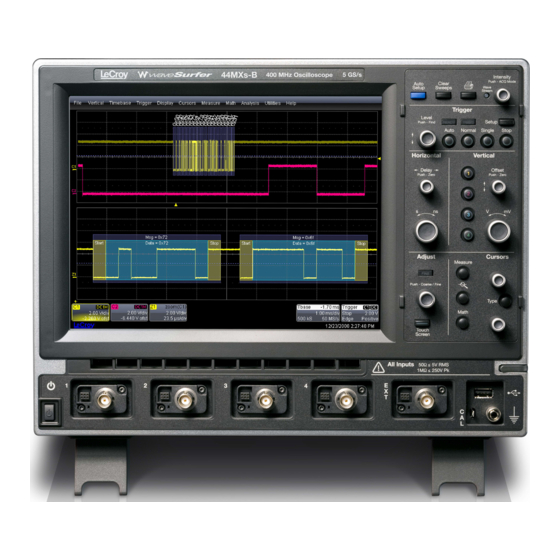
DIGITAL OSCILLOSCOPE
WAVESURFER 44MXS-B
(LECROY)
Published under Authority of the Secretary of the Air Force
T.O. 33K3-4-3760-1
28 FEBRUARY 2014
Advertisement
Table of Contents

Subscribe to Our Youtube Channel
Related Manuals for LeCroy WAVESURFER 44MXS-B


Summary of Contents for LeCroy WAVESURFER 44MXS-B
-
Page 1: Calibration Procedure
T.O. 33K3-4-3760-1 TECHNICAL MANUAL CALIBRATION PROCEDURE DIGITAL OSCILLOSCOPE WAVESURFER 44MXS-B (LECROY) Distribution Statement C - Distribution authorized to U. S. Government agencies and their contractors for official use or for administrative or operational purposes only, 28 February 2014. Requests for this document shall be referred to AFMETCAL, 813 Irving-Wick Dr W, Heath, OH 43056-1199. -
Page 2: Calibration Description
T.O. 33K3-4-3760-1 DIGITAL OSCILLOSCOPE WAVESURFER 44MXS-B (LECROY) 1 CALIBRATION DESCRIPTION: Table 1. Test Instrument (TI) Performance Test Characteristics Specifications Method Range: 2 mV to 1 V/div, 50 coupled; DC Accuracy Compared to a standard 2 mV to 10 V/div, 1 M coupled... -
Page 3: Equipment Requirements
T.O. 33K3-4-3760-1 2 EQUIPMENT REQUIREMENTS: Minimum Use Calibration Sub- Noun Specifications Equipment Item Range: 0 to 30 VDC 2.1 OSCILLOSCOPE Fluke CALIBRATOR 9500B/3200AF Accuracy: 0.475% of setting Range: Leveled Sinewave: 600 to 720 mV p-p, 10 kHz to 400 MHz Accuracy: Flatness, 5% relative to 50 kHz;... -
Page 4: Calibration Process
T.O. 33K3-4-3760-1 4 CALIBRATION PROCESS: NOTE Unless otherwise specified, verify the results of each test and take corrective action whenever the test requirement is not met, before proceeding. 4.1 DC ACCURACY CALIBRATION: 4.1.1 Set the TI controls as follows: File Recall Setup…... - Page 5 T.O. 33K3-4-3760-1 Mean Mean Mean Vertical 2 (press twice to turn channel off) Vertical 3 (press twice to turn channel off) Vertical 4 (press twice to turn channel off) Close 4.1.2 Connect the Oscilloscope Calibrator to the TI 1 connector. 4.1.3 Set the Oscilloscope Calibrator for the first value listed in the Applied column of Table 2 into 1 M.
- Page 6 T.O. 33K3-4-3760-1 Table 2. (Cont.) Volts/Div Applied (VDC) Limits (VDC) 200 m +600 m +574.0 to +626.0 m -600 m -626.0 to -574.0 m 500 m +1.5 +1.4365 to +1.5635 -1.5 -1.5635 to -1.4365 1.00 +2.874 to +3.126 -3.126 to -2.874 2.00 * +5.749 to +6.251 -6.251 to -5.749...
- Page 7 T.O. 33K3-4-3760-1 4.1.13 Set the TI controls as follows: Volts/div 2.00 mV Coupling DC50 Close 4.1.14 Repeat steps 4.1.3 through 4.1.12 for the applicable values listed in Table 2 with the Oscilloscope Calibrator output impedance set to 50 . 4.1.15 Disconnect the Oscilloscope Calibrator from the TI 1 connector and connect to the TI 2 connector.
- Page 8 T.O. 33K3-4-3760-1 VERTICAL 3 Offset 750 mV Averaging 5, then OK VERTICAL 4 Offset 750 mV Averaging 5, then OK Measure Measure Setup Show Table (checked) Mean Mean Mean Mean Vertical 2 (press twice to turn channel off) Vertical 3 (press twice to turn channel off) Vertical 4 (press twice to turn channel off) Close 4.2.2 Connect the Oscilloscope Calibrator to the TI 1 connector.
- Page 9 T.O. 33K3-4-3760-1 4.2.9 Verify the TI P1:mean(C1) indication is within +735.75 to +764.25 mV. 4.2.10 Set the Oscilloscope Calibrator OUTPUT to OFF. 4.2.11 Set the TI controls as follows: Offset 750 mV Coupling DC50 Close 4.2.12 Set the Oscilloscope Calibrator Amplitude for -750 mV DC into 50 . Set the OUTPUT to ON. 4.2.13 Repeat steps 4.2.4 through 4.2.10.
- Page 10 T.O. 33K3-4-3760-1 Volts/div 100 mV Coupling 50ΩDC Averaging 5, then OK VERTICAL 3 Volts/div 100 mV Coupling 50ΩDC Averaging 5, then OK VERTICAL 4 Volts/div 100 mV Coupling 50ΩDC Averaging 5, then OK Measure Measure Setup… Show Table (checked) Peak to peak Peak to peak Peak to peak Peak to peak...
- Page 11 T.O. 33K3-4-3760-1 4.3.3 Set the Oscilloscope Calibrator for a 600 mV p-p leveled sine wave at 50 kHz into 50 . Set the OUTPUT to 4.3.4 Adjust TI Trigger Level as necessary for a stable display. 4.3.5 Adjust the Oscilloscope Calibrator output controls for a TI P1:pkpk(C1) indication of as close as possible to 600 mV.
- Page 12 T.O. 33K3-4-3760-1 4.4 TRIGGER CALIBRATION: 4.4.1 Set the TI controls as follows: File Recall Setup… Recall Default Horizontal s ns 10.00 Volts/div 100 mV Coupling 50ΩDC Averaging 10, then OK Volts/div 100 mV Coupling 50ΩDC Averaging 10, then OK Vertical 3 Volts/div 100 mV...
- Page 13 T.O. 33K3-4-3760-1 Vertical 4 (press twice to turn channel off) Close 4.4.2 Connect the Oscilloscope Calibrator to the TI 1 connector. 4.4.3 Set the Oscilloscope Calibrator for a 10 kHz, 700 mV p-p leveled sinewave into 50 . Set the OUTPUT to 4.4.4 Adjust the Oscilloscope Calibrator for 7.2 div of vertical deflection on the TI display.
- Page 14 T.O. 33K3-4-3760-1 4.4.20 Set the TI controls as follows: Trigger Trigger Setup Slope Positive Source Close 4.4.21 Set the Oscilloscope Calibrator OUTPUT to ON. 4.4.22 Repeat steps 4.4.4 through 4.4.12 for TI C3 using C3 controls and settings. 4.4.23 Disconnect the Oscilloscope Calibrator from the TI 3 connector and connect to the TI 4 connector. 4.4.24 Press TI Vertical 3, then Vertical 4 to turn C3 off and C4 on.
- Page 15 T.O. 33K3-4-3760-1 Trigger Normal Measure Measure Setup… Show Table (checked) Frequency Close 4.5.2 Connect the Oscilloscope Calibrator to the TI 1 connector. 4.5.3 Set the Oscilloscope Calibrator for a 600 mV p-p leveled sinewave at 10 MHz into 50 . Set the OUTPUT to 4.5.4 Verify the TI P1:freq(C1) indication is within -100 to +100 Hz.
Need help?
Do you have a question about the WAVESURFER 44MXS-B and is the answer not in the manual?
Questions and answers