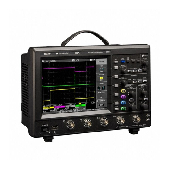
LeCroy WaveJet 300A series Getting Started Manual
Oscilloscopes
Hide thumbs
Also See for WaveJet 300A series:
- Specification (2 pages) ,
- Manual (60 pages) ,
- Quick reference manual (13 pages)
Table of Contents
Advertisement
Quick Links
Advertisement
Table of Contents

Related Manuals for LeCroy WaveJet 300A series


Summary of Contents for LeCroy WaveJet 300A series
-
Page 1: Getting Started
Getting Started Manual WaveJet 300A Series ® Oscilloscopes... - Page 2 , 2009 PRIL...
- Page 3 © 2009 by LeCroy Corporation. All rights reserved. LeCroy, ActiveDSO, JitterTrack, WaveLink, WavePro, WaveMaster, WaveSurfer, WaveJet, and Waverunner are registered trademarks of LeCroy Corporation. Other product or brand names are trademarks or requested trademarks of their respective holders. Information in this publication supersedes all earlier versions. Specifications subject to change without notice.
-
Page 4: Table Of Contents
Getting Started Manual INTRODUCTION ................7 SAFETY REQUIREMENTS .............. 8 Safety Symbols and Terms ..................8 Operating Environment ....................9 Cooling Requirements ..................... 10 AC Power Source ....................10 Power and Ground Connections ................11 Calibration ....................... 11 Cleaning ........................11 Abnormal Conditions .................... - Page 5 WaveJet 300A Series Trigger Controls ....................29 Horizontal Controls ..................29 Vertical Controls ..................... 30 Zoom Control Knobs ..................30 Special Features Controls ................31 General Control Buttons ................. 32 UNDERSTANDING DISPLAY INFORMATION ......34 Grid Area ......................... 34 Top Status Bar ......................35 Bottom Status Bar ....................
- Page 6 Getting Started Manual Other Parameters ................... 54 Statistics ........................54 DISPLAY FORMATS ..............55 Display Setup ......................55 Display Types ......................56 Zooming Waveforms ....................56 Replay Mode ......................57 SAVE AND RECALL ..............58 Saving and Recalling Scope Settings ..............58 Saving and Recalling Waveforms ................
- Page 7 WaveJet 300A Series BLANK PAGE WJ-A-GS-E Rev A...
-
Page 8: Introduction
Getting Started Manual INTRODUCTION This brief guide includes important safety and installation information for your WaveJet Series oscilloscope, along with brief operating procedures to get you started capturing, viewing, and analyzing your waveforms. WJ-A-GS-E Rev A... -
Page 9: Safety Requirements
WaveJet 300A Series SAFETY REQUIREMENTS This section contains information and warnings that must be observed to keep the instrument operating in a correct and safe condition. You are required to follow generally accepted safety procedures in addition to the safety precautions specified in this section. -
Page 10: Operating Environment
Getting Started Manual Installation (Overvoltage) Category rating per EN 61010-1 safety standard and is applicable for the oscilloscope front panel measuring CAT I terminals. CAT I rated terminals must only be connected to source circuits in which measures are taken to limit transient voltages to an appropriately low level. -
Page 11: Cooling Requirements
WaveJet 300A Series temporary conductivity caused by condensation must be expected. Protection Class 1 refers to a grounded equipment, in which protection against electric shock is achieved by Basic Insulation and by means of a connection to the protective ground conductor in the building wiring. -
Page 12: Power And Ground Connections
Getting Started Manual Power and Ground Connections The instrument is provided with a grounded cord set containing a molded three-terminal WARNING polarized plug and a standard IEC320 (Type C13) connector for making line voltage and Electrical Shock Hazard! safety ground connection. The AC inlet Any interruption of the protective ground terminal is connected directly to the conductor inside or outside of the... -
Page 13: Abnormal Conditions
WaveJet 300A Series Abnormal Conditions Operate the instrument only as intended by the manufacturer. WARNING If you suspect the scope’s protection has Any use of the scope in a manner not been impaired, disconnect the power cord specified by the manufacturer may and secure the instrument against any impair the instrument’s safety unintended operation. -
Page 14: When Your Scope Is Delivered
LeCroy shall not be responsible for any defect, damage, or failure caused by any of the following: a) attempted repairs or installations by personnel other than LeCroy representatives or b) improper connection to incompatible equipment, or c) for any damage or malfunction caused by the use of non-LeCroy supplies. - Page 15 WaveJet 300A Series repairs, among other services, are available through special supplemental support agreements. Inquire at your LeCroy customer service center or national distributor. WJ-A-GS-E Rev A...
-
Page 16: Specifications
Getting Started Manual SPECIFICATIONS Vertical System Bandwidth (-3 dB @ 50 ohms): WJ354A 500 MHz WJ352A WJ334A 350 MHz WJ332A WJ324A 200 MHz WJ322A WJ314A 100 MHz WJ312A Input Channels: 4 (WJ354A/334A/324A/314A); 2 (WJ352A/332A/322A/312A) Rise Time (typical): WJ354A 750 ps WJ352A WJ334A 1.00 ns... -
Page 17: Max Input Range
WaveJet 300A Series Input Impedance: WJ354A WJ352A 1 Mohm+/-1.5 % || 16 pF, 50 ohm +/-1.5 % WJ334A WJ332A WJ324A WJ322A 1 Mohm+/-1.5 % || 20 pF WJ314A WJ312A Input Coupling: WJ354A WJ352A GND, DC1Mohm, AC1Mohm, DC50ohm WJ334A WJ332A WJ324A WJ322A GND, DC1Mohm, AC1Mohm WJ314A... -
Page 18: Horizontal System
Getting Started Manual Sensitivity: WJ354A WJ352A 2 mV/div~10 V/div (1 Mohms), 2 mV/div~2 V/div (50 ohms) WJ334A WJ332A WJ324A WJ322A 2 mV/div~10 V/div (1 Mohms) WJ314A WJ312A DC Gain Accuracy: +/-(1.5 % + 0.5% of full scale) Offset Range: 2 mV/div~50 mV/div +/-1 V 50.2m V/div~500m V/div +/-10 V... -
Page 19: Acquisition Processing
WaveJet 300A Series Standard Record Length: 500 kpts/Ch Standard Capture Time: up to 250 µs at 2 GS/s (WJ354A/352A/334A/332A/324A/322A); up to 500 µs at 1 GS/s (WJ314A/312A) Acquisition Processing Averaging: Up to 256 sweeps Peak Detect: Period of 1 ns Trigger System Trigger Modes: Auto, Normal, Single, Stop Trigger Types: Edge, Pulse Width, Period, Pulse Count, TV... -
Page 20: Display
Getting Started Manual USB: 1 front panel mounted USB and 1 rear panel mounted USB 1.1 port. Probes 1 PP006A probe per channel (WJ354A/352A/334A/332A); 1 PP010 probe per channel (WJ324A/322A/314A/312A) Scale Factors: Automatically or manually selected depending on probe used Display Type: Color, 7.5"... -
Page 21: Measure Tools
WaveJet 300A Series Measure Tools Standard Parameters: Vertical Horizontal Other Maximum Tr 20-80% Integral Minimum Tf 80-20% Skew Peak-Peak Tr 10-90% Skew@Level Tf 90-10% Cycle RMS Frequency Mean Period Cycle Mean No. of +Pulses No. of -Pulses Base +Pulse Width Top-Base -Pulse Width +Overshoot... - Page 22 Getting Started Manual Environmental: Temperature (operating): 10 to 35 °C Temperature (storage): -20 to +60 °C Humidity (operating): 5 to 80% RH (non-condensing) Altitude (operating): up to 2000 m Certifications: EN61326:1997 +A1:1998 +A2:2001 +A3:2003 EN61010-1:2001 61010-1, 2nd edition CAN/CSA C22.2 No 61010-1-04 WJ-A-GS-E Rev A...
- Page 23 WaveJet 300A Series Declaration of Conformity: Meets intent of the European Council Directives 73/23/EEC for product safety and 89/336/EEC for electromagnetic compatibility. This declaration is based upon compliance of the WaveJet oscilloscope to the following standards: EN 61326: 1997 +A1:1998 +A2:2001 +A3:2003 EMC requirements for electrical equipment for measurement, control, and laboratory use.
- Page 24 Getting Started Manual WJ-A-GS-E Rev A...
- Page 25 WaveJet 300A Series Toxic or Hazardous Substances and Elements Hexavalent Polybrominated Polybrominated Lead Mercury Cadmium Chromium Biphenyls Diphenyl Ethers Part Name (Pb) (Hg) (Cd) (PBB) (PBDE) PCBAs Mechanical Hardware Sheet Metal Plastic Parts Cable Assemblies Display Power Supply Fans Battery for Processor Power Cord Ext Power Supply (if present)
-
Page 26: Power-Up And Installation
Getting Started Manual POWER-UP AND INSTALLATION Power-Up Press the power switch at bottom-left of the front of the scope to apply or remove power. Software You can find out the scope's software and hardware configuration as follows: 1. Press the front panel U button. -
Page 27: Updating The System Software
WaveJet 300A Series Updating the System Software System software updates are downloaded through the USB memory port in the front of the scope. 1. Insert the USB memory device, containing the software update file in a root directory, into the USB port at the front of the scope. -
Page 28: Probes
Getting Started Manual PROBES LeCroy provides a passive probe for each WaveJet oscilloscope channel, as follows: PP006A 350 and 500 MHz PP010 100 and 200 MHz Probe Compensation Passive probes must be compensated to flatten overshoot. This is accomplished by means of a trimmer at the connector end of the probe. -
Page 29: Front Panel Controls
WaveJet 300A Series FRONT PANEL CONTROLS Front Panel Buttons and Knobs The control buttons of the WaveJet Series front panel are logically grouped into analog and special function areas. The following table provides an explanation of the front panel push buttons and knobs. WJ-A-GS-E Rev A... -
Page 30: Trigger Controls
Getting Started Manual Trigger Controls -- Selects the trigger threshold level. EVEL Press the L knob to have the scope find EVEL the trigger level automatically. -- Displays the trigger setup menu. ETUP Triggers the scope after a time-out, even if the trigger conditions are not met. Triggers the scope each time a ORMAL signal is present that meets the conditions set... -
Page 31: Vertical Controls
WaveJet 300A Series Vertical Controls -- Adjusts the vertical offset of each FFSET channel individually. -- Adjusts the volts/division setting OLTS (vertical gain) of the channel selected. -- If the channel is already HANNEL UTTONS ON, the channel button makes the channel active. -
Page 32: Special Features Controls
Getting Started Manual Special Features Controls -- In intensity mode, use NTENSITY EPLAY this knob to adjust the brightness of your waveforms. The intensity value is displayed at the top of the screen at far right. Pressing the button changes its function to Replay (history) mode, which allows you to scroll backwards in time to view past acquisitions. -
Page 33: General Control Buttons
WaveJet 300A Series -- Enables you to save up to five waveforms in internal scope memory. You can also recall waveforms. -- This button enables you to ECALL save or recall scope setups and waveforms from internal scope memory or from USB memory. - Page 34 Getting Started Manual -- This button closes menus and pop- LOSE up boxes. When menus are more than one layer deep, it closes the top-most menu with each successive press of the button. WJ-A-GS-E Rev A...
-
Page 35: Understanding Display Information
WaveJet 300A Series UNDERSTANDING DISPLAY INFORMATION Grid Area The grid area contains several indicators to help you understand triggering. Indicators are coded to the channel colors (yellow here for channel 1). Trigger Delay -- This indicator is located along the top edge of the grid. -
Page 36: Top Status Bar
Getting Started Manual Trigger Level -- This indicator is located at the right edge of the grid. The value is displayed below the grid. Press the trigger level knob to reset the level to 50%. Zero Volts Level -- This indicator is located at the left edge of the grid. -
Page 37: Bottom Status Bar
WaveJet 300A Series Bottom Status Bar The status bar below the grid displays cursor (time and frequency) information and additional trigger setup information. Message Line At the very bottom of the scope display is the message line. Prompts and error messages are displayed on this line at far left. -
Page 38: Turning On Traces
Getting Started Manual TURNING ON TRACES To turn on a channel trace, simply press the channel button. This action also displays a setup menu for that channel. The setup menu displayed (1/2 or 2/2) will be the one that was displayed when the trace was last turned on. -
Page 39: Vertical Settings And Channel Controls
WaveJet 300A Series VERTICAL SETTINGS AND CHANNEL CONTROLS Choosing Coupling To select an input coupling mode, turn on the channel whose coupling you want to change by pressing the appropriate channel button. Select Coupling from page 1/2 of the channel menu, then the coupling mode from the next menu. -
Page 40: Inverting Waveforms
Getting Started Manual Inverting Waveforms Set this item to On to invert the waveform. Adjusting Sensitivity Activate the channel you want to adjust; there does not need to be a signal applied. Turn the volts per division knob in the VERTICAL group of controls. The volts/div that you set is displayed in the top line of the trace descriptor label. -
Page 41: Adjusting The Waveform's Position
WaveJet 300A Series Adjusting the Waveform's Position Turn the vertical offset adjust knob in the VERTICAL group of controls. The offset value is displayed in the bottom line of the trace descriptor label. WJ-A-GS-E Rev A... -
Page 42: Sampling Modes
Getting Started Manual SAMPLING MODES Sampling modes are accessed by pressing the S button in the ETUP HORIZONTAL control group. There are three basic sampling modes: Normal -- real-time mode Peak Detect -- the maximum and minimum values that occur in a zone twice the sampling period are detected. -
Page 43: Triggering
WaveJet 300A Series TRIGGERING Trigger Types Trigger modes are accessed by pressing the S button in the TRIGGER control ETUP group of buttons and selecting Type from the “Trigger” menu: Press the Type menu button to select Edge, Pulse Width, Period, Pulse Count, or TV triggering. -
Page 44: Pulse Width Triggering
Getting Started Manual Pulse Width Triggering Source lets you choose a channel input or an external input. Select positive or negative polarity. Coupling modes comprise AC, DC, HF Reject, and LF Reject Select Pulse Width to set “less than” and “greater than” criteria and range limits, and to set time values. -
Page 45: Period Triggering
WaveJet 300A Series Period Triggering Source lets you choose a channel input or an external input. Select positive or negative polarity. Coupling modes comprise AC, DC, HF Reject, and LF Reject Select Interval Time to set “less than” and “greater than” criteria, and to set a time value. -
Page 46: Pulse Count Triggering
Getting Started Manual Pulse Count Triggering Source lets you choose a channel input or an external input. Select positive or negative polarity. Coupling modes comprise AC, DC, HF Reject, and LF Reject Select No. of Pulse to set the number of pulses to count before the scope triggers. -
Page 47: Tv Triggering
WaveJet 300A Series TV Triggering Press the Type menu button to select a standard: NTSC, PAL, or Custom. Source lets you choose a channel input or an external input. Select Slope to set positive or negative polarity. Select TV Setting to set up the TV trigger. WJ-A-GS-E Rev A... -
Page 48: Horizontal Trigger Setup
Getting Started Manual Horizontal Trigger Setup Turn the D knob in the HORIZONTAL control group to ELAY adjust the trigger's horizontal position. The trigger location is shown by a marker at the top of the grid and the time value is given in the status bar above the grid: Post-trigger delay is indicated by a left-pointing arrow at the left edge of the grid. -
Page 49: To Set Up An Edge Trigger
WaveJet 300A Series The trigger level is indicated by a “T” to the right of the grid. The value is given below the grid A “T” with an underscore, as shown here, indicates a negative voltage level. A “T” with a superscore (overbar) indicates a positive voltage level. - Page 50 Getting Started Manual If you want to set a holdoff time, use the A knob to set a value. Push DJUST the A knob to toggle between DJUST fine and coarse adjustment. To set a holdoff time of zero seconds, turn the knob fully counterclockwise until Off is displayed in the “Holdoff”...
-
Page 51: Waveform Measurements
WaveJet 300A Series WAVEFORM MEASUREMENTS Measuring with Cursors Cursors are important tools that aid you in measuring signal values. Cursors are boundary markers that you can move across the grid. Use cursors to make fast, accurate measurements and to eliminate guesswork. Cursor Measurement Selections Time cursors are vertical lines that you move horizontally to measure the difference in time or frequency values between... -
Page 52: Cursor Placement
Getting Started Manual Amplitude cursor values are displayed in the bottom line of the trace label for each channel: Note that the value depends on the time/div setting shown in the top line of each trace label. Cursor Placement Use the A knob to move cursors horizontally and DJUST vertically. -
Page 53: Parameter Measurements
WaveJet 300A Series PARAMETER MEASUREMENTS Waveform analysis typically begins with the measurement of parameters. Parameter measurement tools determine a wide range of waveform properties. Use them to automatically calculate many attributes of your waveform, like rise time, rms voltage, and peak-to-peak voltage, for example. You can make common measurements on one or more waveforms. -
Page 54: Standard Horizontal Parameters
Getting Started Manual Top-Base -- Measures the difference between upper and lower levels in two- level signals. Differs from pkpk in that noise, overshoot, undershoot, and ringing do not affect the measurement. +Overshoot -- Amount of overshoot following a rising edge specified as percentage of amplitude. -
Page 55: Other Parameters
WaveJet 300A Series Other Parameters Integral -- Computes area of waveform between cursors relative to zero level. Values greater than zero contribute positively to the area; values less than zero negatively. Skew -- Measures from the 50% crossing of the first edge of a channel to the 50% crossing of a second channel. -
Page 56: Display Formats
Getting Started Manual DISPLAY FORMATS Display Setup The Display menu is accessed by pressing the D button on the front panel. ISPLAY Display types comprise YT (voltage versus time), XY, and XY Triggered. Select points if you want to see actual sample points only. Select lines if you want to see interpolated vectors between points. -
Page 57: Display Types
WaveJet 300A Series Display Types This is volts versus time, or dBm versus frequency for the FFT function. Asynchronous XY mode. Inputs must be connected to channel 1 and channel 2. When this mode is selected Auto is indicated as the trigger mode and the timebase control cannot be adjusted: Synchronous XY mode. -
Page 58: Replay Mode
Getting Started Manual The zoom factor is displayed above the grid: The zoom magnification factor is the ratio of the timebase of the zoom trace to that of the input waveform. Zoom delay represents the portion of the input waveform being zoomed. As you turn the Horizontal delay knob, this value becomes positive or negative depending on whether the zoom is left (+) or right (-) of center. -
Page 59: Save And Recall
WaveJet 300A Series SAVE AND RECALL Saving and Recalling Scope Settings You can save scope settings to internal memory or USB memory. The “Save/Recall” menu is accessed by pressing the S front panel button. ECALL Five memory locations available. Setup files named with current time and date. -
Page 60: Saving And Recalling Waveforms
Getting Started Manual Saving and Recalling Waveforms Reference waveforms can be saved in internal memory (five locations) or in USB memory (limited by memory capacity of USB device). When you save a waveform, the setup is saved also. You can display up to five reference waveforms at the same time. Press REF to turn them all off together. -
Page 61: Waveform Math
WaveJet 300A Series WAVEFORM MATH Standard math functions comprise addition, subtraction, multiplication, and FFT. The “Math” menu is accessed by pressing the M front panel button in the VERTICAL control group. Source can be any channel, but not another math trace. Select math operator +, -, x, or FFT. -
Page 62: Utilities
Getting Started Manual UTILITIES Print Screen Device allows you to choose an output device, such as USB or Printer. When Printer is selected the paper size and background choices are available. Selectable file formats are .tif, .bmp, and .png. Background lets you select a black or white background for the grid. -
Page 63: Configuration
WaveJet 300A Series Configuration -- Page 1/2 Language selects a UI local language. No reboot is required to accept a change in language. Select Date & Time to set the current time and to determine the clock mode at the bottom of the screen: real time clock (RTC) or trigger time stamp (TRG). -
Page 64: Configuration
Getting Started Manual Configuration -- Page 2/2 Beep enabled gives audible confirmation of button presses and knob rotations. Panel Lock disables all front panel buttons and knobs until unlock is selected from this menu, which remains continuously displayed. Use the front panel A knob to adjust the grid intensity DJUST from 0 to 100%. -
Page 65: Calibration
WaveJet 300A Series Calibration Calibrations can be set to occur automatically. Autocalibration occurs three minutes after power-up and whenever there is a change in ambient temperature of 5 °C. Select Self Calibration to perform a manual calibration. WJ-A-GS-E Rev A... -
Page 66: Status & Update
Getting Started Manual Status & Update The Status selection displays a pop-up box showing system status, including serial number and software revision. Press to close the pop-up box. LOSE Update is used to load firmware updates from USB memory. § § § WJ-A-GS-E Rev A... - Page 67 Thank You for Purchasing a WaveJet Oscilloscope.
Need help?
Do you have a question about the WaveJet 300A series and is the answer not in the manual?
Questions and answers