Table of Contents
Advertisement
Quick Links
Advertisement
Table of Contents

Subscribe to Our Youtube Channel
Related Manuals for DentalEZ TruSim


Summary of Contents for DentalEZ TruSim
- Page 1 ®...
-
Page 2: Table Of Contents
Torso ..........................6 Light Post (Optional) ....................7 Monitor Mount (Optional) ..................7 Section III Operation ................... 8 Section IV Care Maintenance ........................ 9 Handpieces ........................10 Plastic and Coated Metal Surfaces ...............10 Section V User Service Information ............11 Limited Warranty ....................12 Tubing Diagram Wiring Schematic Template TruSim Simulator... -
Page 3: Section I Introduction
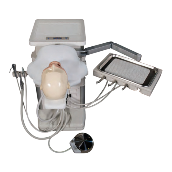
DentalEZ TruSim Simulator. ® The TruSim Simulator is available in either a mobile Power Supply (situated on wheels) or stationary configuration with • 115V, 15 Amp, 60 Hz., as applicable either a delivery unit style operator arm and short Air Pressure - 551.6 pKa (80 PSI) -
Page 4: Explanation Of Symbols And Signs
SIMULATOR HIGHEST LEVEL = Manufacturer NOTICE The pictures and illustrations in this manual depict the mobile model of the TruSim Unit. The stationary model has exactly the same specifications except 32-1/16" the mobile unit is situated on wheels and is equipped with a brake mechanism, while the stationery unit is situated on small rubber feet. -
Page 5: Section Ii Set Up
Do not modify this equipment without authorization from DentalEZ. If this NOTICE equipment is modified, appropriate inspection and testing must be conducted to ensure continued safe Installation by an authorized DentalEZ dealer service use of equipment. technician is recommended. NOTICE WARNING... -
Page 6: Utilities
Power this device is being installed as a replacement, always vacuum fitting Cord have a licensed electrician inspect the existing facility in the utility electrical and complete the electrical portion of the service com- device installation. partment. TruSim Simulator... -
Page 7: Manikin Head
Section II Set Up TruSim Simulator NOTE: If not using city water lines, fill the optional 3. Place the instruments in the handpiece holders. water bottle. NOTE: The instrumentation can be moved left/right depending on the dexterity of the operator. -
Page 8: Light Post (Optional)
Installation instructions are also included with the monitor mount. CAUTION DO NOT exceed monitor weight capacity of 20 lbs.. Light Power Cord 3/16" Hex Light Double Post Pivot Light Post Mount Monitor (Customer Supplied) Outlet #2 Phillips Screw- driver Rear Panel Monitor Cables TruSim Simulator... -
Page 9: Section Iii Operation
Section III Operation TruSim Simulator 1. Push the master switch “M” to the ON posi- WARNING tion to activate air/water to the handpieces. DO NOT place objects above the rated load of 27.2 NOTE: The handpieces are factory adjusted to 30 kg (60 lbs.) on the work surface or 13.6 kg (30 lbs.) -
Page 10: Section Iv Care
2. Empty the vacuum solids collector. 3. Empty the optional water bottle and vacuum waste water bottles after each use. . For mobile simulator, push the brake button to the OFF Position to unlock feet and store under cabinet. TruSim Simulator... -
Page 11: Handpieces
Section IV Care TruSim Simulator Handpieces Hidden Maintenance Coolant Water Spray Handpiece Drawer Water The coolant spray volume for the handpieces can be Adjustment Pressure regulated as follows: Gauge 1. Locate the handpiece water adjustment valves Handpiece inside the maintenance drawer. -
Page 12: Section V User Service Information
Section V User Service Information If the problem arises, contact your local DentalEZ WARNING full-service dealership. (See Limited Warranty, Page 12.) Be prepared to supply the following product informa- Before servicing, always disconnect the tion: external power by unplugging the unit from the power receptacle. -
Page 13: Limited Warranty
TruSim Simulator The DentalEZ Group and its employees are proud of the products we provide to the dental community. We stand behind these products with a warranty against defects in material and workmanship as provided below. In the event that you experience difficulty with the application or operation of any of our products, please con- tact our Technical Service Department at our expense at 1-866-DTE-INFO (1-866-383-4636). -
Page 14: Tubing Diagram
TruSim Simulator ™ 1/4" RED (Mobile) Tubing Diagram 1/8" GREEN WATER ADJUSTMENT (Clean/City Water & Central Vac.) COLLECTOR HIGH VOLUME WATER RETRACTION EVACUATOR VALVE 1/8" BLUE COLOR CODE GAUGE = Air 1/8" BLACK SALIVA Yellow = Signal Air (Master) 1/8" BLUE 1/8"... - Page 15 TruSim Simulator ™ 1/4" RED (Stationary) WATER 1/8" GREEN Tubing Diagram ADJUSTMENT COLLECTOR (Clean/City Water & Central Vac.) WATER RETRACTION HIGH VOLUME VALVE EVACUATOR 1/8" BLUE GAUGE SALIVA COLOR CODE EJECTOR 1/8" BLACK = Air 1/8" BLUE 1/8" GREEN WATER CONTROL...
-
Page 16: Wiring Schematic
TruSim Simulator ™ Wiring Schematic CHASSIS GROUND DUPLEX OUTLET 15 AMP CIRCUIT BREAKER (004659) 115V RECEPTACLE (3648-365) 24 VDC OUT TO CONTROL BOARD BLUE (AC LINE NEUTRAL) BROWN (AC LINE HOT) PN: 2662-294A... -
Page 17: Template
SCALE: 1.000 10.31" 4.96" Ø 0.53" Anchor Hole (2) Places Clearance for a 1/2-13 Bolt (If Applicable) TruSim Center Line Electrical Outlet Location *Water Regulator Location ELECTRICAL: Provide 120V, 20 amp power supply with duplex receptacle by contractor. AIR: Ø... - Page 18 2500 Highway 31 South Bay Minette, Alabama 36507 1-866-DTE-INFO Fax: (251) 937-0461 www.dentalez.com © DentalEZ Alabama, Inc. Printed in USA PN: 2717-255A November, 2014...
Need help?
Do you have a question about the TruSim and is the answer not in the manual?
Questions and answers