
Related Manuals for DentalEZ aXcs Magellan


Summary of Contents for DentalEZ aXcs Magellan
- Page 1 ® aXcs Magellan CMU 1 2 3 4 5 6 7 8 9 0 1 2 1 2 3 4 5 6 7 8 9 0 1 2 1 2 3 4 5 6 7 8 9 0 1 2...
-
Page 2: Table Of Contents
Pivot Hardware ............. 48 Utility Service Center .......... 27 Product Support Services ......49 Handpieces ............27-28 Basic Electrical Box Wiring Diagram Optional Features ..........29 Power Module Wiring Diagram Tubing Diagram Template (USC Base) aXcs Magellan CMU Installation, Operation and Care Manual... -
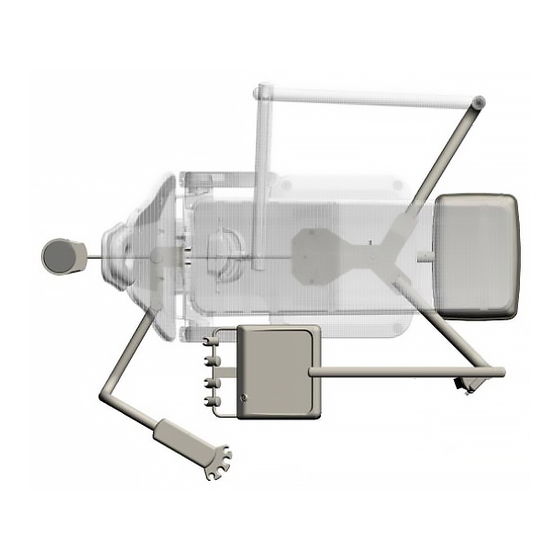
Page 3: Introduction
Before proceeding, please review the illustration Mounted Unit (CMU). below to become familiar with the components of The aXcs Magellan is designed to provide trouble- the aXcs Magellan. free service when installed, operated and maintained After the Magellan unit is installed, please review the according to the instructions in this manual. -
Page 4: Specifications
Specifications Delivery Head Unit Weight Utility Service Center Clean Water Reservoir Capacity ..(Euro 16-3/4") 18-1/2" 14" (Euro 17") R 24" 22-5/8" R 26-1/2" 3-1/2" 5-1/4" 21-1/4" 27-3/4" 27-3/4" 41-1/4" 13-1/4" 6-5/8" 9-3/4" - 21" 5-1/2" 13" aXcs Magellan CMU... -
Page 5: Basic Components
Post Pivot Pin Unpacking Cartons Two Thrust Bearings Four Thrust Washers The aXcs Magellan components are packaged and shipped according to the carton diagrams shown 3/8" x 2-1/4" Hex-head Bolt* below and on Page 5. .382/.393 ID x .683 OD Washer* 13/32"... - Page 6 Pump Cover Umbilical Slot Template 14" Nylon Cable Tie Light Extension Cord aXcs Magellan Carton — NOTICE — For any questions about an order, please contact a DentalEZ Equipment customer service representative at 1-866-DTE-INFO. Utility Service Center Assembly Foot Control & Installation Hardware...
-
Page 7: Section Ii Pre-Installation
Section II Pre-installation aXcs Magellan CMU ® Utility Service Center — IMPORTANT NOTICE — DO NOT DISCARD the USC template USC Carton Contents: after use. Neatly refold it and replace it in • Utility Service Center (USC) the back of this manual •... -
Page 8: Electrical Contractor's Procedure
NOTE: If the recommended location is not met, the Water Actuator USC base or the optional power module may interfere Valve with the 115 VAC receptacle. Assembly CHAIR SIDE 115 VAC Receptacle USC Base — NOTICE — aXcs Magellan CMU... -
Page 9: Section Iii Installation
Magellan Unit Support *IMPORTANT NOTE: This manual contains instructions for installing an aXcs Magellan Unit on a pre-tubed or non-pre-tubed chair. Pre-tubed chairs have an umbilical assembly running along the top casting through the cantilever and out the base (pump) -
Page 10: Umbilical Assembly
Umbilical Assembly Spacer, 1/2" Bolt & Lock Washer Level Set B #10 Screw & (parallel) Lock Washer Magellan Unit Support 3/8" Bolts 8" Tie Wrap White Cable aXcs Chair 3/8" Set Screws (for leveling) Clamp Set A aXcs Magellan CMU... - Page 11 Section III Installation aXcs Magellan CMU ® J/V-Chair - Route the chair umbilical Syringe Air/ Lift Hydraulic assembly through the front slot in the chair Water Lines Cylinder Hoses casting and continue as shown in the illustration below. Then secure using the two 1"...
-
Page 12: Magellan Unit Post
Trim off the excess cord, then reattach the 4. Position a thrust washer onto the flat hospital plug to the cord. member of the Magellan unit post. aXcs Magellan CMU... -
Page 13: Delivery Head
Section III Installation aXcs Magellan CMU ® 10. Locate the 1/4" x 3/4" long set screw in the 3/8" Hex-head Bolt Rubber Cap threaded hole on the Magellan unit support. 3/8" Lock Washer Then tighten the 1/4" x 3/4" set screw to prevent the pivot pin from rotating. -
Page 14: Handpiece Tubing
14. Match and connect the tubes and wires from securely lock it into the chassis. the magellan arm umbilical assembly to the tubes and wires of the chair umbilical assembly. 4. Hang the handpiece tubing coupler in the holder. aXcs Magellan CMU... -
Page 15: Syringe Tubing
Section III Installation aXcs Magellan CMU ® Euro-Style Head Syringe Tubing Traditional Head NOTE: The holder on the left is dedicated to the syringe, but any of the remaining three holders may be used. Clamp NOTE: The numbers on the bracket should match those on the chassis next to the valve block. -
Page 16: Delivery Head Tray With Pad
3. Place the tray on the pad. — NOTICE — Euro-Style Head For tubing connections, see the tubing 1. Place the pad on the tray holder. diagram in the back of this manual. 2. Place the tray on the pad. aXcs Magellan CMU... -
Page 17: Water Heater (Optional)
aXcs Magellan CMU Section III Installation ® Assistant's Arm (Optional) Male Quick Connect Carton Part Contents: Coupling • Assistant’s Arm Female Quick • Tubing Retainer Bracket Connect • Mounting Bracket Assembly Couplings • High-volume Evacuator Valve Handle • Saliva Ejector Valve Handle •... - Page 18 J-Chair or V-Chair, 12. Pass the tubing and wires from the assistant's please refer to the Installation Instructions arm through the strain relief bushing in the included with the controller. cantilever cover. aXcs Magellan CMU...
- Page 19 Section III Installation aXcs Magellan CMU ® Saliva Ejector Saliva Ejector Valve open High-Volume Evacuator (HVE) HVE Valve open NOTE: Refer to the tubing diagram in the back of this manual if necessar y. Instrument Holder Closed 1/2" Port 1/2" closed Tubing Syringe Air/...
-
Page 20: Basic Electrical Box (Optional)
It may be necessary to remove an existing screw and reinsert the screw with the green ground wire screw and reinsert the screw with the green ground wire attached. attached. NOTE: Make sure the air valve in the USC is open. aXcs Magellan CMU... -
Page 21: Fiber Optics Electrical (Optional)
Section III Installation aXcs Magellan CMU ® Fiber Optics-Electrical (Optional) NOTE: For fiber optics electrical connections, see the basic electrical box or power module system wiring diagrams in the back of this manual. Traditional Head Black White Fiber Optic Control Assembly NOTE: If the optional power module was in- stalled, installation of the fiber optics electrical... -
Page 22: Fiber Optic Tubing (Optional)
Tubing Cover color match the wires Euro-Style Head — CAUTION — NOTE: The holder on the left is dedicated to the syringe, but any of the remaining three holders may be used. aXcs Magellan CMU... -
Page 23: Light Or Monitor Pole (Optional)
Section III Installation aXcs Magellan CMU ® Light or Monitor Pole (Optional) • • • • (one each) • NOTE: The numbers on the bracket should match • those on the chassis next to the valve block and at the •... - Page 24 — CAUTION — Bolt Tray Hole Plug Tray Arm Spacer End Cap 1/4" ID Nut 1/2" ID Nut (Left Hand Thread) NOTE: The 1/4" ID nut has left hand threads. Set Screw Hole Tray/Arm Assembly Monitor Pole aXcs Magellan CMU...
-
Page 25: Chipblower (Optional)
Section III Installation aXcs Magellan CMU ® Chipblower (Optional) — CAUTION — Wet/Dry 6" Clear Toggle Valve Tubing 3" Tubing Drive Air Valve Chip Air Valve 6" Tubing Shuttle Assembly Valve Chipblower Flat-head Screws Installation, Operation and Care Manual... -
Page 26: Finalizing Usc Installation
(Refer to Page 8, Step 4.) (See connection “D”.) (This is the drive air line for the foot control.) (See connection “E”.) (See connection “A”.) (See connection “B”.) aXcs Magellan CMU... -
Page 27: Reprogramming Chair
Reprogramming Chair “H” in photo on Page 25.) 16. If an optional fiber optic electrical system Special instructions for the DentalEZ E-3000 is installed, attach the electrical leads of the Chair: To prevent the Magellan unit post from power pack transformer with connection “J”. -
Page 28: Section Iv Testing
WET/DRY Toggle Valve Master ON/OFF Switch Air/Water Regulators Water Coolant Valves • water regulator (Traditional 40 PSI Delivery • air regulator Head Shown) NOTE: If the water or air regulator needs calibration, perform the following three steps. aXcs Magellan CMU... - Page 29 Section IV Testing aXcs Magellan CMU ® (Traditional Delivery Head Shown) Air Pressure Adjustment Screws ISO 4-Line Connector Tubing Coupler Handpiece Tubing (Insert Air Pressure Gauge Here) Drive Air Pressure Flush Valve — CAUTION — Installation, Operation and Care Manual...
-
Page 30: Optional Features
Section IV Testing Fiber Optics Optional Features Syringe (Euro Style) Chipblower NOTE: If syringe adjustments are necessar y, per- form the following three steps: — NOTICE — EURO-STYLE Adjustment Screw Assistant's Vacuum Accessories OPEN aXcs Magellan CMU... -
Page 31: Section V Operation
aXcs Magellan CMU Section V Operation ® • CUT OFF Delivery Head • • Instrument • Hanger Rotate • • • Master Switch Controls Traditional & Euro-Style Head ON/OFF Handpiece Holder Screw IMPORTANT: • Master ON/OFF Switch Collector/ Swing-Away Instrument Hanger Filter Traditional Head Euro-Style Head... -
Page 32: Handpieces
NOTE: When making necessary air pressure adjustments, refer to the air pressure gauge located at • the front of the deliver y head to check the approxi- mate amount of air pressure delivered to the hand- piece. aXcs Magellan CMU... -
Page 33: Syringe
Section V Operation aXcs Magellan CMU ® Flush System Euro-Style Flush Toggle Adjustment Ferrule Valve Body Screws FLUSH NOTE: Flushing the water line in the handpiece can be done by operating the FLUSH valve while either fully depressing or not depressing the foot control. Foot Control Syringe NOTE:... -
Page 34: Clean Water System (Optional)
NOTE: When the foot control is released, the fiber Syringe optics light will stay on for approximately ten seconds NOTE: to allow inspection of the cutting site. See the syringe operating instructions on Page 32. aXcs Magellan CMU... -
Page 35: Section Vi Care
Section VI Care aXcs Magellan CMU ® Cleaning ON/OFF Clean Water System • • — NOTICE — — CAUTION — • Disinfecting NOTE: After cleaning the high-volume evacuator, saliva • ejector and solids collector, evacuate two cups of Vac-U-Ez cleaning solution (one cup each) through the high-volume evacuator and saliva ejector to sanitize the system. -
Page 36: Section Vii User Service Information
○ ○ ○ ○ ○ ○ y t l . r i " 4 i l i t y t l & l t t l l i l t t l r i o l l aXcs Magellan CMU... -
Page 37: Handpiece
Section VII User Service Information aXcs Magellan CMU ® Delivery Head (continued) n i l y t l s l i l t t l t t y t l o l f Handpiece . r i o l f s ' r y t l y t l... - Page 38 . f f . l o , y l y r t . l o . l o d i l o i t d i l o i t aXcs Magellan CMU...
-
Page 39: Arm System
Section VII User Service Information aXcs Magellan CMU ® Arm System y l r y f i y f i y l r t f i y l r i l e y t l c t i c t i y t l c t i i t c... -
Page 40: Service Instruction
Section VII User Service Information Service Instruction Model Number Serial Number (See Product Support Services, Page 49.) • • • Delivery (Model and serial numbers found on the Head Chassis underside of the delivery head chassis.) • • aXcs Magellan CMU... -
Page 41: Section Viii Parts List/Diagrams
aXcs Magellan CMU Section VIII Parts List/Diagrams ® (inside) Utility Service Center a l l t l i t a l t l i t a l Power Module t a l t a l & t a l t a l t l i t a l c t i... -
Page 42: Assistant's Arm
Section VIII Parts List/Diagrams 1b 1c 1d Assistant's Arm o t t t i u aXcs Magellan CMU... -
Page 43: Fixed/Adjustable Arm
Section VIII Parts List/Diagrams aXcs Magellan CMU ® Fixed/Adjustable Arm i l y Installation, Operation and Care Manual... -
Page 44: Traditional Delivery Head
Section VIII Parts List/Diagrams Traditional Delivery Head c i t e l l & t l i aXcs Magellan CMU... -
Page 45: Euro-Style Delivery Head
aXcs Magellan CMU ® Section VIII Parts List/Diagrams 2a 2b 12 14 Euro-Style Delivery Head c i t e l l & t l i Installation, Operation and Care Manual... -
Page 46: Foot Control
Section VIII Parts List/Diagrams Foot Control aXcs Magellan CMU... -
Page 47: Air/Water Syringe
Section VIII Parts List/Diagrams aXcs Magellan CMU ® Air/Water Syringe r t r HVE Nozzle i r - i r - Saliva Ejector Nozzle i l a i l a i r - i r - Installation, Operation and Care Manual... -
Page 48: Clean Water System
Section VIII Parts List/Diagrams Clean Water System (Optional) e l t e l t t a l aXcs Magellan CMU... -
Page 49: Pivot Hardware
aXcs Magellan CMU ® Section VIII Parts List/Diagrams Pivot Hardware , t i g i l t i n Installation, Operation and Care Manual... -
Page 50: Product Support Services
Magellan Chair Mounted Unit DentalEZ and its employees are proud of the products we provide in the dental community. We stand behind these products with a warranty against defects in material and workmanship as provided below. And, we have our own in-house repair facility to service our products. - Page 51 aXcs Magellan Unit ® Basic Electrical Box System Wiring Diagram UTILITY SERVICE CENTER VOLTAGE LEGEND (WIRE HARNESS) Brown - N/A Green - Ground Purple - N/A White - 15V, 6.0A Gray - N/A - 17V, 6.0A Black Orange Black/Red 20.0V, .5A Black Black - Common Yellow...
-
Page 52: Power Module Wiring Diagram
Magellan Unit aXcs ® Power Module System Wiring Diagram OUTSIDE VIEW UTILITY SERVICE CENTER (Main Wiring Harness) Brown Purple AMP Connector (1-480274-0) Gray Orange Green Yellow Brown, Purple & Gray (To #9 on AMP Connector) Fully Insulated 1/4" Female Quick Disconnect Black (To #8 on AMP Connector) Orange... -
Page 53: Tubing Diagram
DELIVERY HEAD Coolant Air 1/8" Blue Signal Air 1/8" Black SYRINGE *WIRE ASSEMBLY, FIBER OPTICS (Black & White) Drive Air 1/4" Red *WIRE ASSEMBLY, SCALER OR CURING LIGHT aXcs Magellan Unit 1/4" Red (Blue & Gray) ® MASTER 1/8" 1/8" Red 1/8"... - Page 54 Chair Side 18-3/4" USC Base Suggested Electrical Outlet Location 15-18" + 1/32" 4-3/4" 5-11/16" 3-11/16" Ø 7/8" through 5-1/8" 1-1/8" 2-1/8" DRAIN Horizontal Center Line WATER 8-5/8" VACUUM + 1/32" 2" 1/2" 3 x Ø 5/8" through 7-9/16" Chair Center Line 4 x for #10-32 Anchors...
- Page 55 2500 Highway 31 South Bay Minette, Alabama 36507 Phone: 1-866-DTE-INFO Fax: (251) 937-0461 www.dentalez.com P. N. 2717-203B © DentalEZ Alabama, Inc. Printed in U. S. A. June, 2002...
Need help?
Do you have a question about the aXcs Magellan and is the answer not in the manual?
Questions and answers