Table of Contents
Advertisement
Quick Links
Advertisement
Table of Contents

Related Manuals for Extron electronics MTPX Series


Summary of Contents for Extron electronics MTPX Series
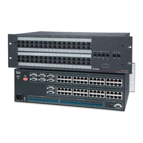
- Page 1 MTPX Series Mini Twisted Pair Matrix Switcher 68-1285-01 Rev. C 04 09...
- Page 2 Precautions Safety Instructions • English Warning Power sources • This equipment should be operated only from the power source indicated on the product. This This symbol is intended to alert the user of important operating and maintenance equipment is intended to be used with a main power system with a grounded (neutral) conductor. The (servicing) instructions in the literature provided with the equipment.
- Page 3 FCC Class A Notice This equipment has been tested and found to comply with the limits for a Class A digital device, pursuant to part 15 of the FCC Rules. Operation is subject to the following two conditions: (1) this device may not cause harmful interference, and (2) this device must accept any interference received, including interference that may cause undesired operation.
-
Page 5: Table Of Contents
Table of Contents Chapter One • Introduction ...................... 1-1 About this Manual ........................1-2 About the MTPX Twisted Pair Matrix Switchers ............. 1-2 Twisted pair (TP) cable advantages ..................1-3 Transmission distances ......................1-4 Definitions ............................1-7 Features ............................1-7 Chapter Two •... - Page 6 Table of Contents, cont’d Viewing and adjusting the local output volume ..............3-32 Reading the displayed volume ..................3-33 Example 9: Viewing and adjusting an output volume level ........... 3-36 Defining the Audio/RS-232 wire pair ................... 3-38 Setting the front panel locks (Executive modes) ..............
- Page 7 Chapter Five • Matrix Software ..................... 5-1 Matrix Switchers Control Program ................. 5-2 Installing the software ......................5-2 Using the Matrix Switcher Control software ................ 5-3 Updating firmware ........................5-6 Windows buttons, drop boxes, and trashcan ..............5-10 Windows menus ........................
- Page 8 Table of Contents, cont’d 68-1285-01 C 04 09 All trademarks mentioned in this manual are the properties of their respective owners. MTPX Twisted Pair Matrix Switchers • Table of Contents...
-
Page 9: Chapter One • Introduction
MTPX Twisted Pair Matrix Switchers Chapter One Introduction About this Manual About the MTPX Twisted Pair Matrix Switchers Definitions Features... - Page 10 Introduction About this Manual This manual contains installation, configuration, and operating information for the Extron MTPX Twisted Pair (TP) Matrix Switchers. About the MTPX Twisted Pair Matrix Switchers The MTPX matrix switcher distributes signals that are compatible with the Extron MTP and VTT/VTR product lines.
-
Page 11: Twisted Pair (Tp) Cable Advantages
The MTPX switchers input and output TP signals on RJ-45 connectors. N For best results, use a cable length of at least 50' (15 m) between the TP inputs and outputs and the transmitter and receiver. Additionally, three or six (depending on the matrix size) 15-pin HD and 5-pole 3.5 mm direct insertion input connectors are available for direct RGB (VGA) or other video inputs and stereo audio inputs without an MTP transmitter. -
Page 12: Transmission Distances
Introduction, cont’d Transmission distances The maximum distances are determined by the frequency and resolution of the video signal being routed and which MTPX inputs and outputs (TP or local) are in the full (video source to display) routing path. The tables below and on the next page specify the recommended maximum transmission distances using Extron Enhanced Skew-Free A/V UTP cable or UTP CAT 5, 5e, 6, or 7 cable, terminated with RJ-45 connectors. - Page 13 Table 2 — Recommended maximum TP transmission distances at 60 Hz, Switcher to MTP receiver when the video source is on the MTPX Plus local (VGA) input MTP Receiver OUTPUTS M TP U R A POWER LOCAL INPUTS INPUTS MONO AUDIO LISTED 0.5A MAX 1T23...
- Page 14 Introduction, cont’d Table 3 — Recommended maximum TP transmission distances at 60 Hz, transmitter to receiver using MTPX TP inputs and outputs MTP Transmitter M T P T 15H D A AUDIO MTP Receiver PRE-PEAK POWER .5A MAX MTP U R A OUTPUTS OUTPUT INPUT...
-
Page 15: Definitions
Definitions The following terms, which apply to all Extron matrix switchers, are used throughout this manual: Tie — An input-to-output connection. Set of ties — An input tied to two or more outputs. (An output can never be tied to more than one input.) Configuration —... - Page 16 Introduction, cont’d Operational flexibility — Operations such as input/output selection, setting of presets, and adjustment of audio levels can be performed using the front panel or via either serial port. The serial ports allow remote control via a PC or a control system. •...
-
Page 17: Chapter Two • Installation
MTPX Twisted Pair Matrix Switchers Chapter Two Installation Mounting the Switcher Rear Panel Cabling and Views Front Panel Configuration Port... -
Page 18: Ul Guidelines
Installation Mounting the Switcher UL guidelines The following Underwriters Laboratories (UL) guidelines pertain to the installation of the MTPX into a rack. Elevated operating ambient temperature — If the equipment installed in a closed or multi-unit rack assembly, the operating ambient temperature of the rack environment may be greater than room ambient temperature. -
Page 19: Rear Panel Cabling And Views
Rear Panel Cabling and Views Figure 2-2 shows the rear panel of the MTPX 1616. LOCAL INPUTS LOCAL OUTPUT CONTROL LOCAL LISTED 1T23 I.T.E. RJ - 45 INPUTS OUTPUTS INPUT SELECT 1.6A MAX MONO AUDIO OUTPUTS Figure 2-2 — MTPX 1616 twisted pair matrix switcher N The MTPX 816 and MTPX 168 are housed in the same 2U enclosure, but have fewer input and/or output connectors to accommodate their smaller matrix sizes. -
Page 20: Signal Inputs
Installation, cont’d Signal inputs Inputs (TP) connectors — Connect the TP outputs of compatible MTP or VTT transmitters to these RJ-45 female connectors. Do not connect this device to a computer data or telecommunications network. N You must configure the switcher for the appropriate content on the audio/ RS-232 wire pair (pins 3 and 6) for each TP input. - Page 21 Local (RGB) Inputs connectors — Connect analog computer- video sources to these 15-pin HD female connectors. N The video that is input on this connector is converted to the proprietary TP signal that normally output by the MTP 15HD transmitters, eliminating some of the transmitters in your system. N Extron recommends against tying a local (RGB) input to a local (RGB) output;...
-
Page 22: Signal Outputs
Installation, cont’d N A mono audio connector consists of a tip and sleeve. A stereo audio connector consists of a tip, ring and sleeve. See figure 2-6 to identify the tip, ring, and sleeve parts of the connector when you are making connections for the switcher from existing audio cables. - Page 23 N This connector can also output HD component video, component video, S-video, or composite video if that is the video format of the tied input. • Output only sync signals, no video signals, on the sync pins, 13 and 14. •...
-
Page 24: Rs-232/Rs-422 Connection
Installation, cont’d By default, the audio ties follow the video ties. Audio breakaway, which can be activated via the front panel or under serial port control, allows you to select from any one of the audio input sources and route it separately from its corresponding video source. -
Page 25: Front Panel Configuration Port
VIEW RGBHV AUDIO CONFIG MTPX SERIES MTP MATRIX SWITCHER Figure 2-9 — Front panel configuration port Configuration port — This 2.5 mm mini stereo jack serves the same serial communications function as the rear panel Remote port, but it is easier to access after the matrix switcher has been installed and cabled. - Page 26 Installation, cont’d 2-10 MTPX Twisted Pair Matrix Switchers • Installation...
-
Page 27: Chapter Three • Operation
MTPX Twisted Pair Matrix Switchers Chapter Three Operation Front Panel Controls and Indicators Front Panel Operations Rear Panel Operations Optimizing the Audio Video Adjustments Troubleshooting Configuration Worksheets... - Page 28 INPUTS CONFIG ENTER PRESET VIEW VIDEO AUDIO OUTPUTS MTPX SERIES MTP MATRIX SWITCHER Figure 3-1 — Front panel, MTPX 1616 INPUTS ENTER PRESET VIEW VIDEO AUDIO CONFIG MTPX SERIES...
-
Page 29: Input And Output Buttons
Input and output buttons N See “Front Panel Operations”, later in this chapter for detailed descriptions of the following operations. Primary functions Action: Select input or output for tie being created. Indications: Blink: potential tie/untie. Lit: current tie through Secondary functions Presets Action/ Select a preset in Preset mode. - Page 30 Operation, cont’d Output buttons and LEDs — The output buttons and LEDs have two primary functions (•) and three secondary functions (❏): • Select output(s). • Identify the selected output(s). Mute the audio or RS-232 output. See “Muting and unmuting audio/ ❏...
-
Page 31: Control Buttons
Control buttons N See “Front Panel Operations”, later in this chapter for detailed descriptions of the following operations. Primary functions Action: Save changes Select Preset mode Select View mode Cancel/escape Indication: Blink: save needed Blink: Save preset View mode selected Flashes once Lit: Recall preset ENTER... - Page 32 Operation, cont’d Preset button and LED — The Preset button and LED have two primary functions (•) and two secondary functions (❏): • Activates Save Preset mode to save a configuration as a preset and Recall Preset mode to activate a previously-defined preset. See “Using global presets”...
-
Page 33: I/O Controls
With the Enter, Preset, and View buttons, selects Serial Port and Audio/RS- ❏ 232 Input Configuration mode. See “Selecting the rear panel Remote port protocol and baud rate” on page 3-42. Selects 115200 baud for the rear panel Remote port in Serial Port and ❏... -
Page 34: Front Panel Operations
Operation, cont’d Audio button and LED — The Audio button and LED have two primary functions (•) and five secondary functions (❏): • Selects and deselects audio (or RS-232 if the wire pair is set for RS-232) for a configuration that is being created or viewed. •... -
Page 35: Definitions
Definitions The following terms, which apply to all Extron matrix switchers, are used throughout this manual: Tie — An input-to-output connection. Set of ties — An input tied to two or more outputs. (An output can never be tied to more than one input.) Configuration —... -
Page 36: Creating A Configuration
Operation, cont’d Creating a configuration The current configuration can be changed using the front panel buttons. Change the current configuration as follows: Press the Esc button to clear any input LEDs, output LEDs, or control LEDs that are lit. Select video, audio, or both for configuration by pressing the Video button and/or Audio button. -
Page 37: Example 1: Creating A Set Of Video And Audio Ties
Example 1: Creating a set of video and audio ties The following example ties input 5 to outputs 3, 4, and 8. The steps show the front panel indications that result from your actions. N This example assumes that there are no ties in the current configuration. Press and release the Esc button (figure 3-4). - Page 38 Operation, cont’d Press and release the Output 3, Output 4, and Output 8 buttons (figure 3-7). N The entire set of ties can be canceled at this point by pressing and releasing the Esc button. The Esc LED flashes once. Press and release the Output 3, Output 4, and Output 8 buttons.
-
Page 39: Example 2: Adding A Tie To A Set Of Video And Audio Ties
Example 2: Adding a tie to a set of video and audio ties In the following example, a new video tie is added to the current configuration. The steps show the front panel indications that result from your action. N This example assumes that you have performed example 1. Press and release the Esc button (figure 3-10). - Page 40 Operation, cont’d Press and release the Output 1 button (figure 3-13). Press and release the Output 1 button. The Enter LED blinks to indicate The LED blinks to indicate that the selected the need to confirm the change. video input will be tied to this output. ENTER PRESET OUTPUTS Figure 3-13 —...
-
Page 41: Example 3: Removing A Tie From A Set Of Video And Audio Ties
Example 3: Removing a tie from a set of video and audio ties In the following example, an existing audio tie is removed from the current configuration. The steps show the front panel indications that result from your action. N This example assumes that you have performed example 1 and example 2. Press and release the Esc button (figure 3-16). - Page 42 Operation, cont’d Press and release the Output 4 button (figure 3-19). Press and release the Output 4 button. The Enter LED blinks to indicate the need to confirm the change. The LED blinks to indicate that the selected audio output will be untied. ENTER PRESET OUTPUTS Figure 3-19 —...
-
Page 43: Viewing A Configuration
Viewing a configuration The current configuration can be viewed using the front panel buttons. The View-only mode prevents inadvertent changes to the current configuration. View-only mode also provides a way to mute audio or RS-232 outputs (see “Muting and unmuting audio/RS-232 outputs” on page 3-20). View the current configuration as follows: Press the Esc button to clear any input LEDs, output LEDs, or control LEDs that are lit. - Page 44 Operation, cont’d To select both video and audio for viewing, if necessary, press and release the Video button and the Audio button (figure 3-23) so that both are LEDs are lit. In this example, the Audio LED blinks to indicate audio breakaway (assuming you have performed examples 1, 2, and 3).
- Page 45 Press and release the Video button to deselect video (figure 3-25). The output buttons for outputs that are tied to Input 5 light to indicate audio ties (audio breakaway). VIDEO AUDIO Press the Video The Audio LED button to delesect it. remains lit to indicate that only audio is The LED is unlit...
-
Page 46: Muting And Unmuting Audio/Rs-232 Outputs
Operation, cont’d Muting and unmuting audio/RS-232 outputs Individual audio or RS-232 outputs can be muted or unmuted as follows: N Audio/RS-232 mutes are protected when front panel Lock mode 2 is selected. You can view the status of the audio output (muted or unmuted) in Lock mode 2 but you cannot change it from the front panel. - Page 47 Press the Audio button to toggle the selection on and off. The LED lights when selected. Video cannot be muted. The lit status of the LED is unimportant . VIDEO AUDIO Until you select an input, the buttons for all untied outputs light. OUTPUTS Figure 3-29 —...
-
Page 48: Using Global Presets
Operation, cont’d Press and release the View button to exit View-only mode (figure 3-32). Press the View button to exit View-only mode. CONTROL The View LED returns to the unlit state. All input LEDs and output LEDs return to the unlit state. PRESET VIEW Figure 3-32 —... -
Page 49: Example 6: Saving A Preset
Example 6: Saving a preset The following steps show an example in which the current configuration is saved as a preset. The steps show the front panel indications that result from your actions. Press and release the Esc button (figure 3-34). Press the Esc button to clear all selections. -
Page 50: Example 7: Recalling A Preset
Operation, cont’d Press and release the Enter button (figure 3-37). The current configuration is now stored in memory location 17. Press the Enter button to save the preset. CONTROL ENTER PRESET VIEW All input LEDs return to the The Enter and Preset LEDs unlit state. - Page 51 Press and release the Output 1 button (figure 3-40). Press and release the Output 1 button. The LED blinks to indicate that this preset number is selected but not recalled. CONTROL ENTER PRESET VIEW Preset 17 Preset 18 Preset 19 Preset 20 The Enter LED blinks to indicate the need to recall the preset.
-
Page 52: Viewing And Adjusting The Tp Input Audio Level
Audio Inputs INPUTS Low Audio Output Output Level Level ENTER PRESET VIEW RGBHV AUDIO CONFIG MTPX SERIES OUTPUTS MTP MATRIX SWITCHER Audio System MTPX 3232 Twisted Pair Matrix Switcher No noticeable volume differences between sources Audio Inputs High Audio Output Level CD Jukebox Figure 3-42 —... - Page 53 Audio input level settings, 16-button switchers Output LED View Esc = on, = blinking , = off MTPX Twisted Pair Matrix Switchers • Operation 3-27...
- Page 54 Operation, cont’d Audio input level settings, 32-button switchers Output LED View Esc = on, = off 3-28 MTPX Twisted Pair Matrix Switchers • Operation...
-
Page 55: Example 8: Viewing And Adjusting An Input Audio Level
Example 8: Viewing and adjusting an input audio level N This procedure can only be performed if the audio/RS-232 wire pair of the input is defined as audio (see “Defining the Audio/RS-232 wire pair“ on page 3-38. N Because of the different gain and attenuation display schemes, the input audio levels that result from the following example are shown twice: as displayed on a 16-output button switcher and on a 32-output button switcher. - Page 56 Operation, cont’d Press and release the Input 5 button (figure 3-45). N Select an input that is configured as a TP input. Press and release the Input 5 button. The LED lights. The View and Esc LEDs The output LEDs display the selected input's audio level. display the polarity (gain In this example, the output buttons and View and Esc buttons or attenuation).
- Page 57 Press and release the View ( < ) button several more times (figure 3-47) to decrease the input audio level by 1 dB per button push. Note the output button indication changes that occur each time the View ( < ) button is pressed.
-
Page 58: Viewing And Adjusting The Local Output Volume
Operation, cont’d Viewing and adjusting the local output volume N Output volume is protected when front panel Lock mode 2 is selected. You can view the volume in Lock mode 2 but not adjust it from the front panel. See “Setting the front panel locks (Executive modes)”... -
Page 59: Reading The Displayed Volume
Reading the displayed volume N This section is a detailed look at reading the output volume display on the matrix switcher’s front panel. If you do not need to read the exact value of the volume setting, skip this section. There are 65 steps of volume attenuation, with 1 dB per step (button push), except for 0-to-1, which is 13 dB. - Page 60 Operation, cont’d Audio output volume settings, 16 button switcher • Successive steps of volume increase cause consecutive LEDs to first blink, Output dB of Input LED then light steadily. (On switchers with volume attenuation 32 input buttons, each consecutive LED 5.5% indicates a 1 dB attenuation reduction when blinking and a 2 dB attenuation...
- Page 61 Audio output volume settings, 32-button switcher Output dB of Input LED Output dB of Input LED volume attenuation volume attenuation 53.5% 5.5% 8.5% 56.5% 11.5% 59.5% 14.5% 62.5% 17.5% 65.5% 20.5% 68.5% 23.5% 71.5% 26.5% 74.5% 29.5% 77.5% 32.5% 80.5% 35.5% 83.5% 38.5%...
-
Page 62: Example 9: Viewing And Adjusting An Output Volume Level
Operation, cont’d Example 9: Viewing and adjusting an output volume level In the following example, the audio output volume is viewed and adjusted. The steps show the front panel indications that result from your actions. Audio output volume is displayed differently on different models. See the tables on pages 3-34 and 3-35. - Page 63 Figure 3-53 shows the same volume (41.5%) as in figure 3-52, but displayed on a 32-input-button switcher, such as an MTPX 3232. The input LEDs display the selected output's audio volume level. In this example, the lit input buttons indicate 40 to 41.5 percent of the applied audio input.
-
Page 64: Defining The Audio/Rs-232 Wire Pair
Operation, cont’d Figure 3-55 shows the same volume (61%) as in figure 3-54, but displayed on a 32-input-button switcher, such as an MTPX Plus 3216. The input LEDs display the selected output's audio volume level. In this example, the lit input buttons indicate 61 percent of the applied audio input. The unlit input buttons indicate an audio volume attenuation of 26 dB. - Page 65 View and configure the switcher’s remote port’s serial communications settings as follows: To enter Serial Port and Audio/RS-232 Input Configuration mode, simultaneously press and hold all Control buttons (Enter, Preset, View, and Esc) (figure 3-57). Press and hold the Enter, Preset, View, and Esc buttons. CONTROL ENTER PRESET VIEW Lit input LEDs indicate RS-232 is selected.
-
Page 66: Setting The Front Panel Locks (Executive Modes)
Operation, cont’d Setting the front panel locks (Executive modes) The matrix switcher has three levels of front panel security lock that limit the operation of the switcher from the front panel. The three levels are: • Lock mode 0 — The front panel is completely unlocked. All front panel functions are available. -
Page 67: Performing A System Reset From The Front Panel
Press and hold the Video and Audio buttons simultaneously to turn on Lock mode 2 or to toggle between mode 1 and mode 2. The Video and Audio LEDs blink twice to 2 seconds indicate the mode change. Release the buttons. VIDEO AUDIO VIDEO AUDIO Figure 3-61 —... -
Page 68: Selecting The Rear Panel Remote Port Protocol And Baud Rate
Operation, cont’d Selecting the rear panel Remote port protocol and baud rate N The Remote port settings are protected when front panel Lock mode 2 is selected. You can view the settings in Lock mode 2 but you cannot adjust them from the front panel. - Page 69 To change a value, press and release the button that relates to the desired value (figure 3-64). Press and release the LED(s) to configure the port as follows: Baud rate: Enter — 9600 Preset — 19200 View — 38400 Esc — 115200 Serial protocol: Video —...
-
Page 70: Rear Panel Operations
Operation, cont’d Rear Panel Operations The rear panel has a Reset button that initiates two levels of matrix switcher resets. For different reset levels, press and hold the button while the switcher is running or press and hold the button while you apply power to the switcher. Performing an absolute system reset from the rear panel This function is identical to the front panel system reset (see “Performing a system reset from the front panel”... -
Page 71: Performing A Hard Reset From The Rear Panel
Performing a hard reset from the rear panel The hard reset function restores the switcher to the original factory default settings. All user files and settings are maintained. Perform a hard reset as follows: If necessary, turn off power to the switcher. Press and hold the Reset button on the rear panel while you apply AC power to the switcher (figure 3-67). -
Page 72: Optimizing The Audio
Operation, cont’d Optimizing the Audio Each individual input audio level can be adjusted within a range of -18 dB to +24 dB, so there are no noticeable volume differences between sources and for the best headroom and signal-to-noise ratio. Adjust the audio gain and attenuation as follows: Connect audio sources to all desired inputs and connect the local audio outputs to output devices such as audio players. -
Page 73: Configuration Worksheets
Configuration Worksheets Rather than trying to remember the configuration for each preset, use worksheets to record this information. Make copies of the blank worksheet on page 3-51 (32-input button and -output button switchers) and page 3-53 (16-button switchers) and use one for each preset configuration. Cross out all unused or inactive inputs and outputs. -
Page 74: Worksheet Example 2: Daily Configuration
Operation, cont’d Worksheet example 2: Daily configuration Figure 3-69 continues from worksheet example 1 by showing the video and audio ties that make up the configuration of preset 1. Black lines show video ties and red lines show the audio ties. Input sources Camera/ Camera... -
Page 75: Worksheet Example 3: Test Configuration
Worksheet example 3: Test configuration The A/V system in our fictional organization needs to be fine tuned on a regular basis. Figure 3-70 shows a typical test configuration, with an Extron video test generator (input 12) generating a test pattern to all monitors (outputs 1, 2, 4, 5, and 8). - Page 76 Operation, cont’d 3-50 MTPX Twisted Pair Matrix Switchers • Operation...
- Page 77 MTPX Twisted Pair Matrix Switchers • Operation 3-51...
- Page 78 Operation, cont’d 3-52 MTPX Twisted Pair Matrix Switchers • Operation...
- Page 79 MTPX Twisted Pair Matrix Switchers • Operation 3-53...
- Page 80 Operation, cont’d 3-54 MTPX Twisted Pair Matrix Switchers • Operation...
-
Page 81: Serial Ports
MTPX Twisted Pair Matrix Switchers Chapter Four Programmer’s Guide Serial Ports Host-to-Switcher Instructions Switcher-Initiated Messages Switcher Error Responses Using the Command/Response Tables Command/Response Table for SIS Commands... - Page 82 Programmer’s Guide Serial Ports The switcher has two serial ports that can be connected to a host device such as a computer running the HyperTerminal utility, an RS-232 capable PDA, or a control system. These ports make serial control of the switcher possible. The serial ports are: •...
- Page 83 The switcher-initiated messages are listed below (underlined). (c) Copyright 2008, Extron Electronics MTPX, Vx.xx, 60-nnn-01 The switcher initiates the copyright message when it is first powered on. Vx.xx is the firmware version number and 60-nnn-01 is the switcher part number.
- Page 84 Programmer’s Guide, cont’d Innn Audxx The switcher initiates the Aud message when a front panel input audio level change has occurred. nn is the input number and xx is the dB level. Outnn Volxx The switcher initiates the Vol message when a front panel output audio volume change has occurred.
-
Page 85: Symbol Definitions
Command/Response Table for SIS Commands Symbol definitions = CR/LF (carriage return/line feed) (hex 0D 0A) = Carriage return (no line feed, hex 0D)) • = Space character = Escape key (hex 1B) = Input number (for tie) 00 – (maximum number of inputs for your model) (00 = untied) = Output number 01 –... - Page 86 Programmer’s Guide, cont’d Command/response table for SIS commands Command ASCII command Response Additional description (host to switcher) (switcher to host) Create ties • Commands can be entered back-to-back in a string, with no spaces. For example: 1*1!02*02&003*003%4*8$. • The quick multiple tie and tie input to all output commands activate all I/O switches simultaneously. •...
- Page 87 Command/response table for SIS commands (continued) Command ASCII command Response Additional description (host to switcher) (switcher to host) Audio/RS-232 TP input (wire pair 3 and 6) configuration Configure input as audio Define the audio/RS-232 input as audio, such as provided by an MTP 15HD A transmitter.
- Page 88 Programmer’s Guide, cont’d Command/response table for SIS commands (continued) Command ASCII command Response Additional description (host to switcher) (switcher to host) Audio output volume N The table below the commands defines the value of each audio volume step. X1)] Set the audio volume to a •Vol specific value Example:...
- Page 89 Command/response table for SIS commands (continued) Command ASCII command Response Additional description (host to switcher) (switcher to host) Audio input gain and attenuation N The set gain (G) and set attenuation (g) commands are case sensitive. X1@] Set input audio gain to +dB •Aud value Example:...
- Page 90 Programmer’s Guide, cont’d Command/response table for SIS commands (continued) Command ASCII command Response Additional description (host to switcher) (switcher to host) Save, recall, and directly write presets • If you try to recall a preset that is not saved, the matrix switcher responds with the error code E11. •...
- Page 91 Command/response table for SIS commands (continued) Command ASCII command Response Additional description (host to switcher) (switcher to host) Resets Reset global presets and names Clear all global presets and their names. EX1$ X1$] Reset one global preset Clear global preset Reset audio input levels Reset all audio input levels (gain and attenuation) to 0 dB.
- Page 92 Programmer’s Guide, cont’d Command/response table for SIS commands (continued) Command ASCII command Response Additional description (host to switcher) (switcher to host) View ties, gain, volume, mutes, presets, and DIP switch status (continued) EX1$ View video global preset *1VC • •...• •Vid n+15 configuration...
- Page 93 Command/response table for SIS commands (continued) Command ASCII command Response Additional description (host to switcher) (switcher to host) View ties, gain, volume, mutes, presets, and DIP switch status (continued) X1& X1& X1& X1*] View Input Select DIP Stat switch positions and level/ X1&...
- Page 94 Programmer’s Guide, cont’d Command/response table for SIS commands (continued) Command ASCII command Response Additional description (host to switcher) (switcher to host) Information requests X2%] Information request V (video) matrix size• •A A (audio) matrix size X2^] Request part number See appendix A for part numbers.
-
Page 95: Matrix Switchers Control Program
MTPX Twisted Pair Matrix Switchers Chapter Five Matrix Software Matrix Switchers Control Program Optimizing the Video Button-Label Generator Program... -
Page 96: Installing The Software
Matrix Software Matrix Switchers Control Program The Windows-based Extron Matrix Switchers Control Program communicates with the switcher via the rear panel Remote RS-232/RS-422 port and the front panel Configuration (RS-232) port to provide an easy way to set up ties and sets of ties. The program is compatible with Windows 2000 and Windows XP. -
Page 97: Using The Matrix Switcher Control Software
To run the Matrix Switcher Control Program, click Start > Programs > Extron Electronics > Matrix Switchers > MATRIX Switcher + Control Pgm or click the desktop icon shown at right. - Page 98 Matrix Software, cont’d Choose either the comm port that is connected to the switcher’s serial port or Emulate. N Although IP [LAN] is available for selection, the switcher does not have an Ethernet port. Do not select IP [LAN]. • If you selected a comm port, check the baud rate displayed in the comm port selection window.
- Page 99 Figure 5-5 — Sample program window (complete) Operate the switcher as desired. • To make the control program easier to use, assign a device icon to each input and output. Click on a box that represents an input or output, and drag the desired icon onto the box from the icon palette that appears.
-
Page 100: Updating Firmware
Matrix Software, cont’d Updating firmware The firmware upgrade utility provides a way to replace the firmware that is coded on the switcher’s control board without taking the switcher out of service. Update the switcher firmware as follows: Visit the Extron Web site, www.extron.com, click the Download tab, and then click the Firmware link (figure 5-6). - Page 101 Folder where firmware is installed Figure 5-7 — Downloading firmware upgrade files MTPX Twisted Pair Matrix Switchers • Matrix Software...
- Page 102 Matrix Software, cont’d Connect the computer to either switcher serial port. See chapter 2, “Installation”, for more details. Start the Matrix Switchers Control Program and connect to the matrix switcher. See “Using the Matrix Switcher Control software” in this chapter, steps 1 through 4, starting on page 5-4. Click Tools >...
- Page 103 Figure 5-9 — Confirm window If necessary, change the port number in the device port field: • Rear panel RS-232/RS-422 port, enter 1. • Front panel Configuration port, enter 2. Click the OK button. The Firmware Loader reports, “This process could take several minutes.
-
Page 104: Windows Buttons, Drop Boxes, And Trashcan
Matrix Software, cont’d Windows buttons, drop boxes, and trashcan The buttons, drop boxes, and trash can on the right side of the program window perform the following functions: Power — Unavailable for MTPX Twisted Pair switchers, because the switcher power cannot be controlled via software. Executive Mode —... -
Page 105: Tools Menu
Tools menu Assign device icons — Displays the complete set of input and output device icons. You can drag any of these icons to the input and output boxes. Edit device palette — Allows you to add your own device icon graphics. -
Page 106: Audio-Input Configuration Selection
Matrix Software, cont’d Hardware status — Provides an overall view of the status of the matrix switcher, including the power supply voltages, the temperature status, the Remote RS-232/RS-422 port configuration, and the installed and updated firmware status (figure 5-11). Green — Proper operation. Red —... -
Page 107: Master-Reset Selection
Ties as crosspoints — Displays ties as a matrix of inputs and outputs (figure 5-13). Ties that have been made are indicated as amber (video and audio), green (video only), and red (audio only) boxes. Ties that will take effect when you click the Take button are indicated by +. -
Page 108: Using Emulation Mode
For information about program features, you can access the help program in any of the following ways: • From the Extron Electronics program folder or group, double- click on the MATRIX Switcher+ Help icon (shown at right). • From within the Matrix Switcher Control Program, click on the Help menu on the main screen. -
Page 109: Button-Label Generator Program
By default, the Windows installation creates a C:\Program Files\Extron\ ButtonLabelGenerator directory and places the Button Label Generator icon into a group or folder named “Extron Electronics”. Using the Button-Label Generator software To run the Button-Label Generator program, click Start > Programs > Extron Electronics >... - Page 110 Matrix Software, cont’d In the Systems selection box, choose the CP 300 1616 Series option to match the button label size for your MTPX switcher. Using normal Windows controls, you can create and print labels that can be placed in the label windows on the front panel of the switcher. Click the Clear All Buttons button and create new labels as many times as necessary to make all of the button labels that you need.
- Page 111 MTPX Twisted Pair Matrix Switchers A ppendix A Reference Information Specifications Part Numbers and Accessories Button Labels...
-
Page 112: Appendix A • Reference Information
Reference Information Specifications Video Routing MTPX 816 ......8 x 16 matrix, 3 x 1 local MTPX 168 ......16 x 8 matrix, 3 x 1 local MTPX 1616 ......16 x 16 matrix, 3 x 1 local MTPX 1632 ......16 x 32 matrix, 6 x 2 local MTPX 3216 ...... - Page 113 Video output — main (see receivers’ input specifications) Number/signal type ..... 8, 16, or 32 proprietary analog signals Connectors ........8, 16, or 32 (depending on configuration) female RJ-45 connectors Sync — local inputs and outputs only Input type ........RGBHV, RGBS, RGsB, RsGsBs Output type ........
- Page 114 Reference Information, cont’d Audio output — main (see receivers’ input specifications) Number/signal type ..... 8, 16, or 32 proprietary analog signals Connectors ........8, 16, or 32 (depending on configuration) female RJ-45 connectors Control/remote — switcher host control Serial host control ports ....1 RS-232 or RS-422, rear panel 9-pin female D connector 1 RS-232 front panel 2.5 mm mini stereo jack Baud rate and protocol ....
-
Page 115: Part Numbers And Accessories
Part Numbers and Accessories MTPX matrix switcher part numbers These items are included in each order for a MTPX matrix switcher: Matrix switcher part numbers Replacement part number MTPX 816 60-831-01 MTPX 168 60-830-01 MTPX 1616 60-829-01 MTPX 1632 60-895-01 MTPX 3216 60-896-01 MTPX 3232... -
Page 116: Cables
Reference Information, cont’d Cables Enhanced Skew-Free™ A/V UTP cables are not recommended for Ethernet/LAN applications. Enhanced Skew-Free™ A/V cable Part number UTP23SF Enhanced Skew-Free A/V UTP cable 26-569-xx (cut, various lengths) UTP23SF Enhanced Skew-Free A/V 1000’ UTP 22-141-03 (Bulk) (non-plenum) UTP23SF-4P/1000 Plenum enhanced Skew-Free A/V UTP 22-142-03 cable (bulk), 1000' (300 m) -
Page 117: Connectors
Male-to-male VGA backshell connector cables Part number VGA M-M BK/3, 3' (0.9 m) 26-238-24 VGA M-M BK/6, 6' (1.8 m) 26-238-25 VGA M-M BK/10, 10' (3.0 m) 26-238-26 VGA M-M BK/15, 15' (4.5 m) 26-238-27 VGA M-M BK/25, 25' (7.6 m) 26-238-28 VGA M-M BK/35, 35' (10.6 m) 26-238-16... -
Page 118: Button Labels
Reference Information, cont’d Button Labels Figure A-1 provides blank button labels for 16-button switchers. Figure A-2 on page A-11 provide blanks for 32-button switchers. Feel free to photocopy them or cut them out of the manual, write button information in each button area as desired, and put them in the switcher’s label window. - Page 119 MTPX Twisted Pair Matrix Switchers • Reference Information...
- Page 120 Reference Information, cont’d A-10 MTPX Twisted Pair Matrix Switchers • Reference Information...
- Page 121 Printing Instructions If you print these strips to cut out and use in your switcher: • Print on 17" by 11" (tabloid or ledger) paper, in landscape orientation. • Set page scaling to None. • After printing, verify that the printed strips fit behind the panel. Your printer configuration may cause the strip to be printed smaller or larger than specified. Figure A-2 —...
- Page 122 Reference Information A-12 MTPX Twisted Pair Matrix Switchers • Reference Information...
- Page 123 Extron’s Warranty Extron Electronics warrants this product against defects in materials and workmanship for a period of three years from the date of purchase. In the event of malfunction during the warranty period attributable directly to faulty workmanship and/or materials, Extron Electronics will, at its option,...
- Page 124 Inside Europe Only Inside Asia Only +81.3.3511.7656 FAX Inside China Only +971.4.2991880 FAX Inside USA / Canada Only +1.919.863.1794 +31.33.453.4040 +65.6383.4400 +86.21.3760.1568 +1.714.491.1500 +1.919.863.1797 FAX +31.33.453.4050 FAX +65.6383.4664 FAX +86.21.3760.1566 FAX +1.714.491.1517 FAX © 2009 Extron Electronics. All rights reserved.
Need help?
Do you have a question about the MTPX Series and is the answer not in the manual?
Questions and answers