
Related Manuals for Kramer VP-551X


Summary of Contents for Kramer VP-551X
- Page 1 USER MANUAL MODEL: VP-551X 4K Presentation Matrix Switcher Scaler P/N: 2900-301296 Rev 7 www.kramerAV.com...
-
Page 2: Table Of Contents
Kramer Electronics Ltd. Contents Introduction Getting Started Overview Typical Applications Defining VP-551X 4K Presentation Matrix Switcher Scal er Mounting VP-551X Connecting VP-551X Connecting Output to Balanced/Unbalanced Stereo Audio Acceptor Connecting Balanced/Unbalanced Stereo Audio Source to Balanced Input Microphone Setup Wiring the RJ -45 Connectors... -
Page 3: Introduction
Kramer Electronics Ltd. Introduction Welcome to Kramer Electronics! Since 1981, Kramer Electronics has been providing a world of unique, creative, and affordable solutions to the vast range of problems that confront the video, audio, presentation, and broadcasting professional on a daily basis. In recent years,... -
Page 4: Overview
European Advanced Recycling Network (EARN) and will cover any costs of treatment, recycling and recovery of waste Kramer Electronics branded equipment on arrival at the EARN facility. For details of Kramer’s recycling arrangements in your particular country go to our recycling pages at www.kramerav.com/support/recycling. -
Page 5: Typical Applications
VP-551X is ideal for the following typical applications: • Projection systems in conference rooms, boardrooms, hotels and churches. • Home theater up-scaling. Controlling your VP-551X Control your VP-551X directly via the front panel push buttons (with on-screen menus, or: • By RS-232 serial commands transmitted by a touch screen system, PC, or other serial controller. -
Page 6: Defining Vp-551X 4K Presentation Matrix Switcher Scaler
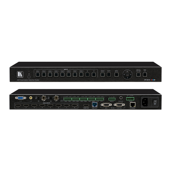
Kramer Electronics Ltd. Defining VP-551X 4K Presentation Matrix Switcher Scaler This section defines VP-551X. Figure 1: VP-551X 4K Presentation Matrix Switcher Scaler Front Panel Feature Function IR Receiver Receives signals f rom the remote-control transmitter. IR LED Lights when the unit accepts IR remote commands. - Page 7 Kramer Electronics Ltd. Figure 2: VP-551X 4K Presentation Matrix Switcher Scaler Rear Panel Feature Function HDMI™ VIDEO INPUT Connect to an HDMI source (f rom INPUT 1 to INPUT 8). Connectors PC 15-pin HD Connect to a computer graphics source.
-
Page 8: Mounting Vp-551X
Kramer Electronics Ltd. Mounting VP-551X This section provides instructions for mounting VP-551X. Before installing, verify that the environment is within the recommended range: • Operation temperature – 0 to 40C (32 to 104F). • Storage temperature – -40 to +70C (-40 to +158F). -
Page 9: Connecting Vp-551X
Kramer Electronics Ltd. Connecting VP-551X Always switch off the power to each device before connecting it to your VP-551X. After connecting your VP-551X, connect its power and then switch on the power to each device. Figure 3: Connecting to the... -
Page 10: Connecting Output To Balanced/Unbalanced Stereo Audio Acceptor
The following are the pinouts for connecting a balanced or unbalanced stereo audio source to the balanced input: Figure 6: Connecting a Balanced Stereo Audio Figure 7: Connecting an Unbalanced Stereo Audio Source to the Balanced Input Source to the Balanced Input VP-551X – Connecting VP-551X... -
Page 11: Microphone Setup
For HDBT cables, it is recommended that the cable ground shielding be connected/soldered to the connector shield. EIA /TIA 568B Wire Color Orange / White Orange Green / White Blue Blue / White Green Brown / White Brown VP-551X – Connecting VP-551X... -
Page 12: Operating And Controlling Vp-551X
• For All & Save or Menu Only & Save Lock modes – Press and hold PANEL LOCK and RESET TO XGA/1080P simultaneously for about 3 seconds. The Panel Lock button light goes out and the front panel buttons are unlocked. VP-551X – Operating and Controlling VP-551X... -
Page 13: Controlling Device Via Osd Menu
2. Press: ▪ ENTER to accept changes and to change the menu settings. ▪ Arrow buttons to move through the OSD menu, which is displayed on the video output. ▪ EXIT to exit the menu. VP-551X – Operating and Controlling VP-551X... - Page 14 Selecting the Input Signal To set the input source: 1. On the front panel press MENU. The menu appears. 2. Click Input and select the input source: ▪ HDMI 1(default) to HDMI 8. ▪ ▪ VP-551X – Operating and Controlling VP-551X...
- Page 15 2560x1080P @60Hz 3840x2160P 24 3840x2160P @24Hz 3840x2160P 25 3840x2160P @25Hz 3840x2160P 30 3840x2160P @30Hz 3840x2160P 50(420) 4k2k @50Hz (4:2:0) 3840x2160P 60(420) 4k2k @60Hz (4:2:0) 3840x2160P 50 3840x2160P @50Hz 3840x2160P 60 3840x2160P @60Hz For HDMI only VP-551X – Operating and Controlling VP-551X...
- Page 16 Hold Time period. Mic Volume Set microphone volume (MIC 1, MIC 2). Embedded In -> Out Apply DSP (def ault) to the embedded audio or ByPass it. VP-551X – Operating and Controlling VP-551X...
- Page 17 Select the inf ormation displayed on-screen during operation: Inf o (def ault) – the inf ormation appears f or 10 seconds. On – the inf ormation appears constantly. Of f – the inf ormation does not appear. VP-551X – Operating and Controlling VP-551X...
- Page 18 HDCP setting of the HDMI/HDCP acceptor to which it is connected. Select Follow Input to change its HDCP output setting according to the HDCP of the input (recommended when the HDMI/HDCP output is connected to a splitter/switcher). VP-551X – Operating and Controlling VP-551X...
- Page 19 Enter TCP port # (5000, by-def ault). TCP Port Enter UDP port # (50000, by-def ault). UDP Port View the current IP address. View the MAC address. MAC ADDRESS View the link status. Link Status VP-551X – Operating and Controlling VP-551X...
- Page 20 Lifetime shows the total number of hours that the machine has been in operation. To view device hours: 1. On the front panel press MENU. The menu appears. 2. Click Advanced. 3. View Lifetime and view device hours. VP-551X – Operating and Controlling VP-551X...
-
Page 21: Operating Via Ethernet
3. Highlight the network adapter you want to use to connect to the device and click Change settings of this connection. The Local Area Connection Properties window for the selected network adapter appears as shown in Figure VP-551X – Operating and Controlling VP-551X... - Page 22 4 (TCP/IPv4) depending on the requirements of your IT system. 5. Click Properties. The Internet Protocol Properties window relevant to your IT system appears as shown in Figure 12 Figure Figure 12: Internet Protocol Version 4 Properties Window VP-551X – Operating and Controlling VP-551X...
- Page 23 Connecting the Ethernet Port via a Network Hub or Switch You can connect the Ethernet port of the VP-551X to the Ethernet port on a network hub or using a straight-through cable with RJ-45 connectors. VP-551X – Operating and Controlling VP-551X...
-
Page 24: Using The Embedded Webpages
Browsing VP-551X Webpages To browse the VP-551X webpages: 1. Open your Internet browser. 2. Type the IP Address of the device in the Address bar of your browser. For example, the default IP Address: VP-551X – Using the Embedded Webpages... - Page 25 Kramer Electronics Ltd. The Input Select webpage appears. Figure 15: VP-551X Input Select Page with Navigation List on Left The model name, FW version and IP Address appear on the lower left side of the main page. The lower part of the screen lets you save the settings and upload a saved setting.
-
Page 26: Selecting Input
The Input Select page enables performing the following functions: • Video Switching on page 25. • Editing an Input on page 26. • Setting the Volume on page 27. VP-551X – Using the Embedded Webpages... - Page 27 2. Click an HDMI button. The selected input is routed to both outputs. Use the freeze icon ( ) to freeze a selected input and the blank button ( ) to display a blank image. VP-551X – Using the Embedded Webpages...
- Page 28 HDMI (for example, for a DVI input signal). Analog – The analog audio input is selected. Embedded – The embedded audio in the HDMI signal is selected. 4. To exit, click . VP-551X – Using the Embedded Webpages...
-
Page 29: Setting Device Parameters
The Device Settings page enables performing the following functions: • Updating the Firmware on page 28. • Changing Ethernet Settings on page 29. • Soft Factory Reset on page 30. VP-551X – Using the Embedded Webpages... - Page 30 3. Select the correct firmware file. 4. Click Open. The selected file appears in the Firmware Update field. 5. Click Upgrade. The new firmware is uploaded, the firmware is upgraded and the system restarts. Upon completion, the webpage refreshes. VP-551X – Using the Embedded Webpages...
- Page 31 After changing the Subnet mask, turn the power off and then on again. VP-551X Any change in the device settings requires confirmation. Figure 20: Device Settings Page – Static IP Confirmation 7. Click OK. Ethernet parameters are changed. VP-551X – Using the Embedded Webpages...
-
Page 32: Changing Output Settings
Selecting Resolution on page 31. • Setting Image Size on the Display on page 31. • Setting Bypass Mode on page 31. • Adjusting the Picture on page 32. • Finetuning Image on page 32. VP-551X – Using the Embedded Webpages... - Page 33 1. In the Navigation pane, click Output Settings. The Device Settings page appears. 2. Open the drop-down box next to Bypass to set the bypass mode to: On – Process the HDMI signal via the scaler. ▪ ▪ Off – No video processing (scaler is bypassed). VP-551X – Using the Embedded Webpages...
- Page 34 1. In the Navigation pane, click Output Settings. The Output Settings page appears. 2. Click Auto Adjust to automatically adjust the image. 3. Use the sliders to adjust the phase, clock, H-Position and V-Position. VP-551X – Using the Embedded Webpages...
-
Page 35: Managing Hdcp
2. Perform the following actions: ▪ Set the HDMI output to follow Input or Output. ▪ Set the HDBT output to follow Input or Output. ▪ Set HDCP on each HDMI input separately to ON or OFF. VP-551X – Using the Embedded Webpages... -
Page 36: Managing Edid
The Copy button is enabled. 4. Click Copy. The selected EDID is copied to the selected inputs and the Copy EDID Results message appears. Figure 26: EDID Page –Copy EDID Results 5. Click Close. VP-551X – Using the Embedded Webpages... -
Page 37: Setting Audio Parameters
Figure 27: Audio Settings Page 2. For each input, set the volume by: ▪ Entering the value in the text box next to the input name. ▪ Sliding the volume switch. The volume is set. VP-551X – Using the Embedded Webpages... - Page 38 Entering the value in the text box next to the input name. Sliding the volume switch. Set Loudness to On or Off (default). ▪ Apply DSP (default) to the embedded audio or Bypass it. VP-551X – Using the Embedded Webpages...
-
Page 39: Setting Rs-232 Port Function
– connect a system controller to the RS-232 port to control Control of VP-551X 551X. ▪ Control of EXTERNAL DEVICE – see Controlling an External Device on page 38. ▪ RS-232 tunneling via Ethernet – see Tunneling via Ethernet on page 40. VP-551X – Using the Embedded Webpages... - Page 40 1. In the Navigation pane, click RS-232. The Audio RS-232 page appears. 2. Set RS-232 Control to Control of EXTERNAL DEVICE: Figure 29: RS-232 Page – Controlling an External Device 3. Under RS-232 Configuration set the RS-232 port parameters to enable communication with the acceptor. VP-551X – Using the Embedded Webpages...
- Page 41 6. Optionally, perform the following for the command: ▪ Click Delete to delete the command. ▪ Click Test to test the command. ▪ Change any of the command configurations. ▪ Enable or disable the command. VP-551X – Using the Embedded Webpages...
- Page 42 2. Set RS-232 Control to RS-232 tunneling via Ethernet: Figure 32: RS-232 Page – Tunneling via Ethernet 3. Under RS-232 Configuration set the RS-232 port parameters to enable communication with the acceptor. 4. Enter the Tunneling Port and click Port Set. VP-551X – Using the Embedded Webpages...
-
Page 43: Setting Webpage Access
Admin). This section describes how to change the password and disable/enable access permission. To change the password: 1. In the Navigation pane, click Authentication. The Authentication page appears. Figure 33: Authentication Page 2. Enter the new password. VP-551X – Using the Embedded Webpages... - Page 44 6. Reenter the webpages. Figure 36: Authentication Page – Password Authentication 7. Click arrow. the webpage reloads. To disable security: 1. In the Navigation pane, click Authentication. The Authentication page appears. 2. Uncheck Authenticate Web Pages access. VP-551X – Using the Embedded Webpages...
- Page 45 2. Check Authenticate Web pages Access. Previous credentials are restored. 3. Click Set changes. The following message appears: Figure 38: Security – Security Enable Confirmation 4. Click OK. appears, and authentication is now required. VP-551X – Using the Embedded Webpages...
-
Page 46: Defining Auto Sync Off
Figure 39: Advanced Page 2. In the Auto Sync Off drop-down box, select the sync mode (Disable, Slow, Fast or Immediate). Figure 40: Advanced Page – Defining Auto Sync Off Auto Sync Off mode is set. VP-551X – Using the Embedded Webpages... -
Page 47: Defining Auto Switching Mode
1. In the Navigation pane, click Advanced. The Advanced page appears. 2. Next to Lock Mode, open the drop-down box to select the lock mode (All, Menu Only, All & Save or Menu Only & Save). Figure 42: Advanced Page – Defining Lock Mode VP-551X – Using the Embedded Webpages... -
Page 48: System Maintenance
To view system status: 1. In the Navigation pane, click Advanced. The Advanced page appears. 2. In System Status area, view power supply, temperature and fan indicators. Figure 43: Advanced Page – System Status VP-551X – Using the Embedded Webpages... -
Page 49: Viewing Device Information
Kramer Electronics Ltd. Viewing Device Information Figure 44: About Page VP-551X – Using the Embedded Webpages... -
Page 50: Upgrading The Firmware
Kramer Electronics Ltd. Upgrading the Firmware Upgrade the firmware via the webpages (see Updating the Firmware on page 28). VP-551X – Upgrading the Firmware... -
Page 51: Technical Specifications
0° to +40°C (32° to 104°F) Conditions Storage Temperature -40° to +70°C (-40° to 158°F) Humidity 10% to 90%, RHL non-condensing Regulatory Saf ety CE, FCC Compliance Environmental RoHs, WEEE 19” 1U Enclosure Size Type Aluminum Cooling Fan ventilation VP-551X – Technical Specifications... - Page 52 3.4kg (7.5lbs) approx. Accessories Included Power adapter cord, IR remote control Optional To achieve specif ied extension distances, use the recommended Kramer cables available at www.kramerav.com/product/VP- 551X Specif ications are subject to change without notice at www.kramerav.com VP-551X – Technical Specifications...
-
Page 53: Default Communication Parameters
1360x768@60Hz 1366x768@60Hz 1400x1050@60Hz 1600x900@60Hz RB 1680x1050@60Hz 1920x1200@60Hz RB 4K2K@50/60Hz (4:2:0), 4K2K@24/25/30/50/60Hz (4:4:4) Computer Graphics Input Resolutions 640x480@60/72/75/85Hz 800x600@56/60/72/75Hz 1024x768@60/70/75Hz 1280x1024@60/75Hz 1280x960@60Hz 1280x720@60Hz 1920x1080@60Hz 1600x1200@60Hz 1280x768@60Hz 1280x800@60Hz 1360x768@60Hz 1366x768@60Hz 1400x1050@60Hz 1680x1050@60Hz 1920x1200@60Hz RB CV Input Resolution 480i/576i VP-551X – Technical Specifications... -
Page 54: Output Resolution Support
Native/preferred timing.. 3840x2160p at 60Hz (16:9) Modeline...."3840x2160" 594.000 3840 4016 4104 4400 2160 2168 2178 2250 +hsync +vsync Detailed timing #1..1920x1080p at 60Hz (16:9) Modeline...."1920x1080" 148.500 1920 2008 2052 2200 1080 1084 1089 1125 +hsync +vsync VP-551X – Technical Specifications... - Page 55 IEEE registration number. 0x000C03 CEC physical address..1.0.0.0 Supports AI (ACP, ISRC).. No Supports 48bpp... Yes Supports 36bpp... Yes Supports 30bpp... Yes Supports YCbCr 4:4:4..Yes Supports dual-link DVI... No Maximum TMDS clock..300MHz Audio/video latency (p).. n/a VP-551X – Technical Specifications...
- Page 56 00000101 = 10F110DE.00100006.040300A1.00800000.630FC 000.00000000.00000000.00000000 00000200 = 24FD8086.00100406.02800078.00000010.63200004.00000000.00000000.00000000 00000300 = 816810EC.00100407.02000010.00000010.00003001.00000000.63104004.00000000 -------- 02070000 = 00FFFFFF.FFFFFF00.2DB20D06.31000000.061C0103.8024248C.C290209C.54508F 26 00000020 = 2152562F.CF00A940.81809040.D1C03159.45596159.819908E8.0030F270.5A80B058 00000040 = 8A00BA88.2100001E.023A8018.71382D 40.582C4500.BA882100.001E0000.00FC0056 00000060 = 502D3535.31580A20.20202020.000000FD.00173D0F.883C 000A.20202020.202001F6 02070100 = 02033BF0.52101F04.13051402.11061522.21205D5E.5F606123.09070783.0100006E 00000020 = 030C0010.00783C20.00800102.030467D8.5DC40178.8007E40F.0000039A.29A0D051 00000040 = 84223050.98360010.0A000000.1C662156.AA51001E.30468F 33.00100900.00001E28 00000060 = 3C80A070.B0234030.20360010.0A000000.1A000000.00000000.00000000.000000E0 VP-551X – Technical Specifications...
-
Page 57: Protocol 3000
Kramer Electronics Ltd. Protocol 3000 Kramer devices can be operated using Kramer Protocol 3000 commands sent via serial or Ethernet ports. Understanding Protocol 3000 Protocol 3000 commands are a sequence of ASCII letters, structured according to the following. • Command format:... -
Page 58: Protocol 3000 Commands
7 = HDMI 8 8 = PC 9 = CV For Output 0 = Line Output 1 = Speaker volume – Volume level 0 to 100; ++ (increase current value by 1dB); -- (decrease current value by 1dB) VP-551X – Protocol 3000... - Page 59 0-(2^16-1). Get Ethernet port COMMAND – TCP/UDP Get the Ethernet port number ETH-PORT? port_type protocol. for UDP: – #ETH-PORT?port_type<CR> port_id port_type #ETH-PORT?UDP<CR> when = TCP: FEEDBACK 5000~5099 ~nn@ETH-PORTport_type,port_id<CR><LF> port_type when = UDP: 50000~50999 VP-551X – Protocol 3000...
- Page 60 0 = Over scan FEEDBACK properties of the selected 1 = Full ~nn@IMAGE-PROPP1,P2…<CR><LF> scaler. 2 = Best fit 3 = Pan scan 4 = Letter box 5 = Under 2 6 = Under 1 7 = Follow in VP-551X – Protocol 3000...
- Page 61 0 = Off 1 = On MUTE? Get audio mute. COMMAND channel – Get mute status of output #MUTE?channel<CR> #MUTE0?<CR> 0 = Output 1 – Scaler FEEDBACK – On/Off mute_mode ~nn@MUTEchannel,mute_mode<CR><LF> 0 = Off 1 = On VP-551X – Protocol 3000...
- Page 62 Get device protocol COMMAND version Get the device protocol version. version: #PROT-VER?<CR> decimal digit #PROT-VER?<CR> FEEDBACK ~nn@PROT-VER3000:version<CR><LF> status – PSU? Get PSU status. COMMAND Get PSU status: #PSU?<CR> #PSU?<CR> 0 = Fail 1 = Pass FEEDBACK ~nn@PSU?status<CR><LF> VP-551X – Protocol 3000...
- Page 63 8 = HDMI 8 – Signal status according to status signal validation: 0 = Off 1 = On Get device serial serial_number – 14 decimal digits, Get the device serial number: COMMAND number. factory assigned #SN?<CR> #SN?<CR> FEEDBACK ~nn@SNserial_number<CR><LF> VP-551X – Protocol 3000...
- Page 64 -BYPASS0<CR> 1 = On FEEDBACK #VIDEO -BYBASSstatus<CR> status – On/Off Get video bypass status. COMMAND Get audio bypass status: VIDEO - BYPASS? # VIDEO -BYPASS?<CR> 0 = Off #VIDEO -BYPASS?<CR> 1 = On FEEDBACK #VIDEO -BYPASS?status<CR><LF> VP-551X – Protocol 3000...
- Page 65 1– On (video disabled) ~nn@VMUTEoutput_id,flag<CR><LF> VMUTE? Get video on output COMMAND output_id Get video on output status: = 1 (scaler) – Video Mute status. flag #VMUTE?output_id_<CR> #VMUTE?1<CR> 0– Off (video enabled) FEEDBACK 1– On (video disabled) ~nn@VMUTEoutput_id,flag<CR><LF> VP-551X – Protocol 3000...
-
Page 66: Result And Error Codes
(Reserved) ERR_RESERVED_8 (Reserved) ERR_RESERVED_9 (Reserved) ERR_RESERVED_10 (Reserved) ERR_RESERVED_11 (Reserved) ERR_RESERVED_12 (Reserved) ERR_EDID_CORRUPTED EDID corrupted ERR_NON_LISTED Device specific errors File has the same CRC – no changed ERR_SAME_CRC ERR_WRONG_MODE Wrong operation mode ERR_NOT_CONFIGURED Device/chip was not initialized VP-551X – Protocol 3000... - Page 67 This limited warranty gives you specific legal rights, and you may have other rights which vary from country to country or state to state. This limited warranty is void if (i) the label bearing the serial number of this product has been removed or defaced, (ii) th e product is not distributed by Kramer Electronics or (iii) this product is not purchased from an authorized Kramer Electronics reseller.
- Page 68 SAFETY WARNING Disconnect the unit f rom the power supply bef ore opening and servicing For the latest information on our products and a list of Kramer distributors, visit our Web site where updates to this user manual may be found.
Need help?
Do you have a question about the VP-551X and is the answer not in the manual?
Questions and answers