Table of Contents
Advertisement
Quick Links
Download this manual
See also:
Operating Manual
Advertisement
Table of Contents

Related Manuals for Kramer VP-701XL


Summary of Contents for Kramer VP-701XL
- Page 1 VP-701XL, VP-703XL, VP-704XL O RAMER PERATION ANUAL Kramer VP-701/3/4XL Manual...
- Page 2 VP-701XL, VP-703XL, VP-704XL O RAMER PERATION ANUAL...
-
Page 3: Table Of Contents
4.4.3 Forcing NTSC output resolution ... 17 4.4.4 Forcing PAL output resolution ... 17 INPUTS AND OUTPUTS ... 18 VP-701XL & VP-703XL rear panel ... 18 VP-704XL rear panel... 18 Computer inputs/outputs ... 18 Video Genlock inputs (VP-704XL only)... 18 Video outputs ... - Page 4 VP-701XL, VP-703XL, VP-704XL O RAMER Items Associated with the Adjust keyers group (Applies only to the VP-704XL) 28 Items Associated with the Adjust sources group... 29 7.6.1 RGB Source Menu Items... 30 7.6.2 CV & YC Source Menu Items (Applies only to VP-704XL)... 32 Items associated with the Adjust resolutions group ...
- Page 5 VP-701XL, VP-703XL, VP-704XL O RAMER 12.1 HD15 connector ... 56 12.2 RS232 / D9 socket ... 56 12.3 4 Pin mini-DIN S-video connector (YC) input... 57 13 SPECIFICATIONS ... 58 PERATION ANUAL...
-
Page 6: Disclaimer
DISCLAIMER This product is intended for professional and/or home use. This product is not intended for use in a medical environment and does not have the required certifications for such use. Similarly, use aboard any aircraft or spacecraft while in flight or as an adjunct to any surface, airborne or marine navigation system or any offshore marine activity, including control of any watercraft, or any use similar to those specifically herein mentioned is prohibited. -
Page 7: Manual Copyright Notice
Direct all inquiries regarding FCC compliance to: KRAMER ELECTRONICS, LTD. Manual Copyright Notice This Operation Manual is the intellectual property of Kramer Electronics ©2007. No portion of this manual may be copied or reproduced in any manner or by any means, including, but not limited to electronic and electro-mechanical, without its express written permission. -
Page 8: Important Safety Instructions
IMPORTANT SAFETY INSTRUCTIONS To insure the best from this product, please read this manual carefully. Keep it in a safe place for future reference. To reduce the risk of electric shock, do not remove the cover from the unit. No user serviceable parts inside. Refer servicing to qualified personnel. 2.1 Power and connections This unit must be connected to a mains socket outlet with a protective earth connection. - Page 9 2.5 Ventilation Slots and openings in the sides of the unit are provided for ventilation. To ensure reliable operation, avoid obstruction of these openings and ensure the unit is installed in a well-ventilated area. 2.6 Intellectual property Some IC chips in this product include confidential and/or trade secret property. Therefore you may not copy, modify, adapt, translate, distribute, reverse engineer, reverse assemble or decompile the contents thereof.
- Page 10 2 IMPORTANT: CONSIGNES DE SECURITE Afin de tirer le meilleur de ce produit, merci de lire attentivement ce manuel. Gardez-le dans un endroit sûr pour pouvoir le consulter à nouveau. Afin de réduire le risque de choc électrique, ne retirez pas l’unité de sa protection. Aucune pièce réparable par l’utilisateur à...
- Page 11 2.4 Emplacement L’installation de cette unité doit se faire dans un endroit frais et sec, éloigné de sources excessives de chaleur, de vibrations, de poussière, d’humidité et de froid. 2.5 Aération Les rainures et les ouvertures sur les cotés de l’unité servent à l’aérer. Pour permettre une utilisation sûre, évitez d’obstruer ces ouvertures et assurez-vous que l’unité...
- Page 12 2 INSTRUCCIONES IMPORTANTES DE SEGURIDAD Para sacar el mejor provecho de este producto, léase este manual con detenimiento. Guárdelo en un lugar seguro para poder hacerle referencia en el futuro. Para reducir el riesgo de calambre, no quite la cubierta del aparato. No hay piezas utilizables dentro.
- Page 13 2.4 Ubicación Este aparato se debe instalar en un lugar seco y fresco, lejos de fuentes de calor excesivas, la vibración, el polvo, la humedad y el frío. 2.5 Ventilación El aparato viene provisto de ranuras y agujeros en los lados para la ventilación. Para asegurar una operación eficaz, se debe evitar la obstrucción de estos agujeros y también asegurar que el aparato se instale en una zona con adecuada ventilación.
- Page 14 2 WICHTIGE SICHERHEITSVORSCHRIFTEN Lesen Sie diese Bedienungsanleitung bitte sorgfältig, um Ihr Produkt optimal nützen zu können, und bewahren Sie sie zum späteren Nachschlagen an einem sicheren Ort auf. Entfernen Sie bitte keinesfalls die Abdeckung, um der Gefahr eines Stromschlags vorzubeugen. Im Inneren des Geräts befinden sich keine Teile, die vom Benutzer gewartet werden können.
- Page 15 Versuchen Sie keinesfalls, das Gerät mit chemischen Lösungsmitteln oder Sprayreinigern zu reinigen, da dies das Gerät beschädigen könnte. Verwenden Sie ein sauberes, trockenes Tuch. 2.4 Aufstellung Das Gerät sollte an einem kühlen, trockenen Ort aufgestellt werden, fern von übermäßiger Wärme, Vibrationen, Staub, Feuchtigkeit und Kälte. 2.5 Belüftung Seitliche Schlitze und Öffnungen sorgen für die Belüftung des Geräts.
- Page 16 2 BELANGRIJKE VEILIGHEIDSINSTRUCTIES Lees deze handleiding zorgvuldig door om het beste uit uw product te halen. Bewaar het op een veilige plek voor raadpleging in de toekomst. Haal nooit het omhulsel van de eenheid af, dit om de kans op een elektrische schok te verminderen.
- Page 17 2.4 Plaatsing Deze eenheid moet geïnstalleerd worden op een koele droge plaats, uit de buurt van bronnen van extreme hitte, vibraties, stof, vocht en kou. 2.5 Ventilatie De sleuven en openingen aan de zijkant van de eenheid zijn voor ventilatie. Zorg er voor dat de eenheid op een goed geventileerde plek geïnstalleerd wordt zodat deze betrouwbaar werkt.
-
Page 18: Device Summary
DEVICE SUMMARY Device Capabilities All units are PC to video down-converters and feature a single video processing and scaling engine, with the VP-704XL also featuring video mixing, keying, Genlock source and fader capabilities. These functions allow the flexibility for handling a wide range of inputs and outputs (both PAL and NTSC), depending on the unit used. -
Page 19: Vp-701Xl
VP-701XL VP-703XL VP-704XL... -
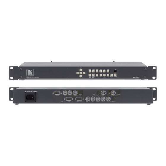
Page 20: Front Panel Controls
(OSD) menu system. Several other buttons on the front panel provide quick access to certain features of the unit. VP-701XL & VP-703XL front panel VP-704XL front panel Button controls A sub-set of the following buttons will be available on the front of the unit,... -
Page 21: Special Button Combinations And Functions
Jumps to the Zoom pan menu item and allows immediate panning of a zoomed image using multi-directional switch. AUTO Activates Auto Track for the analog RGB input TRAK ASPECT Changes the aspect ratio of the output, by cycling between 3 RATIO different settings. -
Page 22: Locking Front Panel Buttons & Ir Remote Control
4.4.2 Locking front panel buttons & IR remote control This can be performed by pressing STANDBY/ON and FREEZE at the same time. All front panel buttons and IR remote commands will be disabled, with the exception of repeating the above combination to unlock the unit and for storing the current locked buttons setting (thus letting you make sure the unit always starts up with the buttons locked). -
Page 23: Inputs And Outputs
The units have different video inputs and outputs depending on your model. VP-701XL & VP-703XL rear panel (Not shown is the VP-701XL’s 12v DC input, nor the VP-703XL’s AC mains input.) VP-704XL rear panel (The VP-704XL’s AC mains input is not shown) -
Page 24: Video Outputs
The CV and YC outputs always function simultaneously and can be set to either standard NTSC or PAL – see ‘Adjust outputs’ for more information. The VP-701XL and VP-703XL both have dual CV/YC outputs – all four connections are active simultaneously, showing identical images. -
Page 25: Infra-Red Remote Control
INFRA-RED REMOTE CONTROL Your unit is compatible with infra-red remote controls as shown below: Resets back to power-on defaults Selects input: 1/2/3=RGB/CV/YC Enables Lock & Mix mode Starts AutoSet (Not used.) Sets Shrink/PIP size & position Adjusts current menu values. Left/right alter current value and up/down alter the... -
Page 26: Menu Layout And Settings Adjustment
MENU LAYOUT AND SETTINGS ADJUSTMENT From here on, we’ll be looking at the menu structure employed in the series and, more importantly, the individual menu items that allow you to take advantage of the power of the unit. You’ll be using the MENU the options and settings available to you. -
Page 27: Group Names And Descriptions
(Model number) Kramer Electronics The first is the ‘welcome’ display shown above indicating the model of the unit. kramerelectronics.com SW: 65. PT: 12, BT: 13 Moving to the next menu item displays the firmware information screen (the numbers on your unit will be different to those shown). The SW number refers to the version of firmware loaded into the unit, this can be upgraded from our website. - Page 28 The top line of the display will show the current output resolution selected. Some units will have a limited number of output resolutions depending on their function (e.g. Down Converters are more limited than Video Scalers). *Not applicable for these units...
-
Page 29: Items Associated With The Adjust Windows Group
This menu item allows you to select the type of signal output your unit will provide. Types of output vary depending on the resolution selected and include various types of component signals Y/R-Y/B-Y or YPbPr, the full range of RGB type signals RGBHV and RGsB (Sync on green). - Page 30 Certain units do not have full flexibility of Window source and Lock source when Genlock or Lock & Mix are active (in the Adjust outputs menu group). See the Specifications for your unit to see if any limitations are present. Adjust windows Zoom level % Changing this option, sets the amount of picture magnification you wish to use for...
- Page 31 Adjust windows Shrink level% [ 50] [On] Shrink Level determines the percentage of the monitor’s total available screen space that the selected Window image occupies. Adjustment is provided for a reduction down to 10% of the overall output size. In most cases, this feature is used for picture-in-picture (PIP) when a background image is being used (for units with overlay abilities).
- Page 32 left as “Simple”, the H/V components of Zoom and Shrink are adjusted equally i.e. H is equal to V. Adjust windows Flicker Reduction The Flicker Reduction menu item will only appear if you have selected a low resolution interlaced output such as PAL or NTSC. If you are using CV or YC outputs, this adjustment may be of interest, particularly when you have line drawings or similar fine detail.
-
Page 33: Items Associated With The Adjust Keyers Group (Applies Only To The Vp-704Xl)
Items Associated with the Adjust keyers group (Applies only to the VP-704XL) Please note that not all units have this sub-menu – it is only present on units with overlaying abilities. Towards the end of this manual you will find a section titled ‘COMMON OPERATIONS’... -
Page 34: Items Associated With The Adjust Sources Group
sometimes 51%. Increasing the softness value will broaden the range of keyed colors so that the keying of images varies depending on how close a color is to the keyed-out range. Adjust keyers Y Key invert The Y Key invert changes the keying characteristics with respect to what colors of the foreground image you wish to ‘key out’. -
Page 35: Rgb Source Menu Items
Since an image pixel is a very small element of the total image, it’s possible for your unit’s Analog to Digital converters to wrongly sample the picture on the edge of each pixel thereby losing image resolution and creating image noise. The Input pixel phase adjustment allows you to change the position (from 0 to 31) where the pixels are sampled, relative to the horizontal sync signal. - Page 36 To make this adjustment, select an RGB source and then provide an image from that source with fine detail, preferably with very sharp vertical lines. Adjust this value until you see the sharpest image. Alternately, adjust this value to give the worst (noisiest/softest) image, and then add or subtract 16 to get the optimum value.
-
Page 37: Cv & Yc Source Menu Items (Applies Only To Vp-704Xl)
The following options are available for this menu item: Mode Normal The two interlaced fields are simply combined together. This will often show artifacts on moving images, but can be Auto Automatically selects Film 3:2 or Medium Range Motion Compensation (M. Comp Med.) depending on whether Film Mode is detected or not. -
Page 38: Items Associated With The Adjust Resolutions Group
Source: YC1 Luma delay On occasion, a video source will have the color portion of the signal offset from the luminance portion. If you’ve ever seen a poor quality comic book that has the outline of the cartoon character’s head in one place on the page but the flesh tones for the head offset slightly, you are seeing the print equivalent of Luminance to Chrominance Phase Delay. - Page 39 800 x 600 60 Hz Image to adjust Change the value to select resolution you want to alter. Typically, the image number currently being used for input or output would be already be selected otherwise immediate feedback to your changes will not be available via your monitor. 800 x 600 60 Hz Interlaced This adjustment specifies whether the image is interlaced or progressive scan.
- Page 40 800 x 600 60 Hz Lines/f [ 628] = This menu controls the total number of lines of video present in the image which includes the vertical Sync pulse, the blanking period and the active video. Changing this option affects the final vertical sync frequency. 800 x 600 60 Hz H/V active A video frame includes both the active area, the portion of the image normally...
-
Page 41: Items Associated With The System Group
Like the H/V Start adjustment, you must use an oscilloscope when making these adjustments so that you know exactly how many milliseconds or microseconds of pulse width you have created. The numbers shown are relative numbers and not an actual time measurement. 800 x 600 60 Hz Sync polarity Sync can be either negative polarity or positive polarity. - Page 42 Normally, the user will examine the added features of each new software release and determine if an update is worth doing in their particular operation. The greater period of time between the current date, and the date shown for the currently installed software, the greater the likelihood that there are useful changes and improvements present in the new release.
- Page 43 57600 and 115200. (This adjustment is provided for those instances where you wish to use the RS-232 control system for your own purposes.) The default baud rate is 57600. System Buzzer The screen labeled ‘Buzzer’ is actually the control for turning the “Beep” “On” or “Off”.
-
Page 44: Rs232 Port
RS232 PORT Connection Your unit is fitted with a standard ‘D9’ socket allowing it to be controlled from a computer or other type of terminal or console with a similar interface. A ‘null-modem’ is not required. See the Specifications section for a detailed pin connection list. -
Page 45: Rs232 / Ip Control Specification
RS232 / IP CONTROL SPECIFICATION PLEASE NOTE: that the VP-701XL RS232 port is used only for FW upgrading. It can t be used for RS232 control. This section outlines how to control a unit via an RS232 using ASCII-based commands. It details how to send and receive serial data to perform many of the functions that a user has access to on the unit. -
Page 46: Packet Format
The ACK flag will be returned as 0 if the command is invalid for some reason – for example a bad FUNCTION, WINDOW, OUTPUT or PAYLOAD value. An ACK=0 message will be otherwise identical to the one you sent, so you know exactly which message has the error. - Page 47 Bit 6 = ACK bit. Should be set to 0 for messages to the unit. ACK=1 returned means message was okay. ACK=0 returned means an error was present in the message. Bit 5 = 0 Reserved for future use. Bit 4 = 0 Reserved for future use. Bit 3 = 0 Reserved for future use.
-
Page 48: Function List
e.g. 000001 is 1 in decimal, 010000 is 65536 in decimal, and FFFFF0 is -16 in decimal. ASCII-hex byte that is the (check) sum of all previous bytes (excluding the SOP F character). E.g. The command F0400410082000001C8 has the checksum of 04+00+41+00+82+00+00+01=C8, so the complete command to send is F0400410082000001C8. - Page 49 Adjust outputs Lock source (connector) Lock method Lock H Shift Lock V Shift Output resolution Output Enable Output image type analogue Output image type digital Background Y Background U Background V CCIR Output Standard Output CV/YC Hue (degrees) Output SC/H Phase Output Luma Bandwidth Output Chroma Bandwidth...
- Page 50 Adjust Windows Program source / Window source (connector) Window Enable Zoom level % Zoom level H % Zoom level V % Aspect ratio in H/V zoom pan % (H) H/V zoom pan % (V) Freeze H/V out shift (H) H/V out shift (V) Lock pixel offset Lock line offset Shrink level %...
- Page 51 U key Softness U key Invert V key min/max (min) V key min/max (max) V key Softness V key Invert Swap fore / background Edge Blend E.blnd guides E.blnd size H E.blnd size V E.blnd gamma H E.blnd gamma V E.blnd compensation Logos (on certain models only) Logo enable...
- Page 52 Field swap Field Offset Testcard TL pos. adj. (left) TL pos. adj. (top) BR size adj. (right) BR size adj. (bottom) Audio input Audio vol Input pixel phase RGB input type RGB contr. (red) RGB contr. (green) RGB contr. (blue) De-int.
- Page 53 Note: You MUST set the Image to adjust value to the correct value first, and only then change the other values - otherwise you may be adjusting the wrong entry. The user should not adjust the Image to adjust entry using the front panel whilst also accessing it via RS232 Image to adjust Interlaced...
-
Page 54: Examples
Not part of menu system Front panel lock Examples Each example shows the packet sent to the unit and its response. When a byte is not required to be sent it is indicated by a ‘- ‘in the table below (since a Read is 6 bytes shorter than a Write). -
Page 55: Reading A Previously Stored Macro
The WIN and OUT bytes are not used for macro reading or writing and should be set to WIN=1A and OUT = 0 The CHA byte indicates the macro we are programming / reading / running. Macro 1 to 5 are CHA 0..4, CHA=5 is restore, CHA 6..7 are Macros 6..7. Macro Restore (CHA=5) is read only, the units restore state is set by sending the Store command (0C8). -
Page 56: Writing To A Macro
the next item in the macro is selected for reading so it is not possible to read the same item twice without first re-reading the number of items in the macro. 9.5.2 Writing to a macro In order to read a preset / macro the following commands must be sent in this specific order –... -
Page 57: Common Operations
COMMON OPERATIONS This section provides step by step instructions for some common operations. 10.1 Operation of the Keyer Some units come equipped with a very powerful Luminance and Chrominance Keyer. The Keyer can take some time to master and below is a breakdown and series of simple steps to help you master the Keyer’s operation When adjusting the values, please bear in the mind the following: The Y value is the Luminance value, so 0 is black and 255 is very bright (white). - Page 58 Adjust any of the Softness values to improve the key. If your input signal is slightly noisy or if you want to soften the edges within the image, then this may require you to decrease the ‘min’ values and increase the ‘max’ values to broaden the range of colors keyed out.
-
Page 59: Troubleshooting And Technical Support
TROUBLESHOOTING AND TECHNICAL SUPPORT If problems are experienced, please read through the symptom topics below in order to resolve the problem. After doing so, if you still need to, contact Technical Support at http://www.kramerelectronics.com. Please have the following details of the problem handy: 11.1 There is no picture on the Output. -
Page 60: The Output Image Is Distorted
adjusting the brightness and contrast of the source input by selecting the Input adjust menu. 11.5 The Output image is distorted. This may occur where some of the areas of the image are very dark and others are very bright. The solution is to adjust the contrast and brightness settings on your Output device to rectify the problem. -
Page 61: Connector Pinouts
CONNECTOR PINOUTS 12.1 HD15 connector 1. Red / Pr / R-Y 2. Green / Y 3. Blue / Pb / B-Y 4. ID2 (input & output linked) 5. GND 6. GND 7. GND 8. GND 9. No connection 10. GND 11. -
Page 62: Pin Mini-Din S-Video Connector (Yc) Input
12.3 4 Pin mini-DIN S-video connector (YC) input 1. Y (Luminance) 2. GND 3. GND 4. C (Chrominance) -
Page 63: Specifications
The unit can be controlled locally via the front panel buttons METHODS: and on-screen display (OSD), remotely via the RS-232 interface (not applicable for VP-701xl) using a D9 female connector or again remotely via the Infrared remote using the infra-red remote unit. - Page 64 VP-701xl: 1.8kg (3.97lbs) approx. VP-703xl and VP-704xl: 2.4kg (5.3lbs) approx. DIMENSIONS: VP-701xl: 18.4cm x 10.2cm x 3.2cm (7.25” x 4” x 1.25” ) W, D, H VP-703xl and VP-704xl: 48.2cm x 17cm x 4.5cm (19” x 6.75” x 1.75”) W, D, H...
Need help?
Do you have a question about the VP-701XL and is the answer not in the manual?
Questions and answers