
Related Manuals for Stahl YL60/2 Series


Summary of Contents for Stahl YL60/2 Series
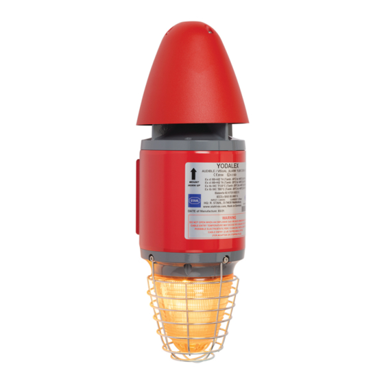
- Page 1 Operating Instructions Additional languages r-stahl.com Audible and visual signalling device Series YL60/2...
-
Page 2: Table Of Contents
Table of Contents General information ....................3 Manufacturer .......................3 Information regarding the operating instructions ..........3 Further documents ....................3 Conformity with standards and regulations ............3 Explanation of symbols ..................4 Symbols used in these operating instructions .............4 Warning notes .....................4 Symbols on the device ..................5 Safety information ....................6 Operating instructions storage ................6 Personnel qualification ..................6... -
Page 3: En En
Further documents • Data sheet For documents in other languages, see r-stahl.com. Conformity with standards and regulations See certificates and EC Declaration of Conformity: r-stahl.com. The device has IECEx approval. See IECEx homepage: http://iecex.iec.ch/ to view the certificate 276786 / YL6060300190 Audible and visual signalling device 2021-05-14·BA00·III·en·00... -
Page 4: Explanation Of Symbols
Explanation of symbols Explanation of symbols Symbols used in these operating instructions Symbol Meaning Tips and recommendations on the use of the device General danger Danger due to explosive atmosphere Warning notes Warning notes must be observed under all circumstances, in order to minimise the risk resulting from design engineering and operation. -
Page 5: Symbols On The Device
Explanation of symbols Symbols on the device Symbol Meaning CE marking according to the current applicable directive. 05594E00 Device certified for hazardous areas according to the marking. 02198E00 Input 15649E00 Output 15648E00 Safety notes that must always be observed: The corresponding data and/or safety-related instructions contained in the operating instructions must be followed for devices with this symbol! 11048E00... -
Page 6: Safety Information
Specialists who perform these tasks must have a level of knowledge that meets applicable national standards and regulations. Additional knowledge is required for activities in hazardous areas! R. STAHL recommends having a level of knowledge equal to that described in the following standards: • IEC/EN 60079-14 (Electrical installations design, selection and erection) •... -
Page 7: Modifications And Alterations
Function and device design Commissioning, maintenance, repair • Only have commissioning and repairs performed by qualified and authorised persons (see "Qualification of the personnel" section). • Before commissioning, make sure that the device is not damaged. • Perform only maintenance work described in these operating instructions. Modifications and alterations DANGER Explosion hazard due to modifications and alterations to the device! -
Page 8: 4.2 Device Design
Function and device design Device design 15256E00 Screws Horn flange Horn cover Cheese head screws Enclosure Audible and visual signalling device 276786 / YL6060300190 Series YL60/2 2021-05-14·BA00·III·en·00... -
Page 9: Technical Data
Technical data Technical data Explosion protection Global (IECEx) Gas and dust IECEx EPS 20.0037X Ex db IIC T. Ex tb IIIC T... °C Europe (ATEX) Gas and dust EPS 20 ATEX 1 007 X E II 2 G Ex db IIC T. E II 2 D Ex tb IIIC T... - Page 10 Technical data Technical data Technical data Product weight 6 kg Electrical data Rated 21.1 to 24 V DC operating voltage Average input Max. current Average power power/max. current consumption consumption [mA] Horn XENON 5J In flash mode 1200 Horn – XENON 5J 12.5 Horn –...
- Page 11 Technical data Technical data Acoustic data Volume ( 110 dB(A) @ 1 m Calculated Inform [80 dB(A)] 15 m max. range Warn [85 dB(A)] Alarm [90 dB(A)] Pole diagram 15288E00 22495E00 276786 / YL6060300190 Audible and visual signalling device 2021-05-14·BA00·III·en·00 Series YL60/2...
- Page 12 Technical data Technical data Optical data Calculated LED disc: max. range Inform Alarm Function Flashing Blinking Flashing Blinking 1 Hz 1 Hz 1 Hz 1 Hz Colour 45 m 58 m 10 m 13 m Amber 69 m 89 m 15 m 20 m Blue...
- Page 13 Technical data Technical data Luminous characteristics Effective luminous Type LED disc LED tower XENON intensity Function Flashing Blinking Flashing Blinking Flashing 1 Hz 1 Hz 1 Hz 1 Hz 1 Hz Colour 41 cd 67 cd 55 cd 90 cd 24 cd Amber 96 cd...
- Page 14 Technical data Technical data Pole diagram XENON: 180° 165° 165° 150° 150° 135° 135° 120° 120° 105° 105° 90° 90° 75° 75° 60° 60° 45° 45° 30° 30° 15° 15° [cd] 0° C0 - C180 C90 - C270 22498E00 LED tower: 180°...
-
Page 15: Transport And Storage
- Signalling device according to configuration - L-bracket - Dust caps For further technical data, see r-stahl.com. Transport and storage • Transport and store the device only in the original packaging. • Store the device in a dry place (no condensation) free of vibrations. -
Page 16: Mounting And Installation
Mounting and installation Mounting and installation Dimensions/Fastening dimensions Dimensional drawings (all dimensions in mm [inches]) – Subject to change 18380E00 Audible and visual signalling device 276786 / YL6060300190 Series YL60/2 2021-05-14·BA00·III·en·00... -
Page 17: Mounting/Dismounting, Operating Position
Mounting and installation Mounting/dismounting, operating position DANGER Explosion hazard due to improper mounting! Non-compliance results in severe or fatal injuries. • Only operate the device if it is not damaged. If the thread is damaged, replace the device immediately. • Only install the device in a clean and dry operating environment. •... -
Page 18: Installation
Mounting and installation • Select a mounting location that is suitable for the signal effect of the device, as well as the required mounting and installation parameters (see "Technical data" section). • Mount the device on a flat surface using the L-bracket and screw holes. •... - Page 19 Mounting and installation • Disconnect the plug connector between the horn flange (7) and PCB (8). 22501E00 • Remove the PCB (8) from the enclosure (6). 22502E00 276786 / YL6060300190 Audible and visual signalling device 2021-05-14·BA00·III·en·00 Series YL60/2...
- Page 20 Mounting and installation 7.3.2 Electrical connections DANGER Explosion hazard due to insufficient protective measures! Non-compliance results in severe or fatal injuries. • Select suitable cables to ensure that the maximum permissible conductor temperatures are not exceeded. • When using core end sleeves, attach them using a suitable tool. •...
- Page 21 Mounting and installation LED Sounder LED Sounder LED Sounder 0V 24V 0V 24V 0V 24V 0V 24V 0V 24V 0V 24 V Sounder 22129E00 Example: Connection diagram for combining multiple devices When doing so: • Observe the maximum permissible single wire cross-sections for the connection terminals –...
- Page 22 Mounting and installation 7.3.3 Configuration The configuration of the device is performed by adjusting the DIP switch on the PCB. The following general audible/visual configuration options are available: XENON horn circuit board 22599E00 DIP switch designation Function OPTIONS General settings Audible settings for sound level 1 Audible settings for sound level 2 "OPTIONS"...
- Page 23 Mounting and installation LED horn circuit board 22505E00 DIP switch designation Function OPTIONS General settings Audible settings for sound level 1 Audible settings for sound level 2 Visual functions General settings 2 General settings "OPTIONS" DIP switch Sound volume reduced by up to 18 dB(A) Sound volume reduced by up to 12 dB(A)
- Page 24 Mounting and installation "OPTIONS 2 and inputs A/B" DIP switch Inputs Sound1 (SW1) LED prog.1 Sound2 (SW2) LED prog.2 Sound1 (SW1) Sound3 (SW3) LED prog.3 Sound2 (SW2) Sound4 (SW4) LED prog.4 B = RI/TI Sound1 (SW1) LED prog.1 Sound2 (SW2) LED prog.2 "SW4"...
- Page 25 Mounting and installation Visual settings DIP switch "SW3" function tower, monochrome LED prog1 LED prog2 LED prog3 LED prog4 Continuous light Double flash 1 Hz Flashing light 1 Hz Rotating light 120 rpm Flashing light 1 Hz Continuous light Flashing light 1.5 Hz Flashing light 2 Hz (dimmed) Flashing light 1.5 Hz Continuous light Flashing light 1 Hz...
- Page 26 Mounting and installation DIP switch "SW3" function disc, monochrome LED prog1 LED prog2 LED prog3 LED prog4 Continuous light Double flash 1 Hz Flashing light 1 Hz Continuous light (dimmed) Flashing light 1 Hz Continuous light Flashing light 1.5 Hz Flashing light 2 Hz (dimmed) Flashing light 1.5 Hz Continuous light Flashing light 1 Hz...
- Page 27 Mounting and installation Audible settings Sou- SW1/SW2 Fre- Sound description Special Sound level quency application Sou- Sou- Sou- Sou- 1000 Hz Changing SW2 05 800 Hz sound 0.5s UK BS5839-1 22571E00 (fire alarm, level crossing) 3100 Hz Safety SW2 04 2500 Hz alarm 0.5s...
- Page 28 Mounting and installation Sou- SW1/SW2 Fre- Sound description Special Sound level quency application Sou- Sou- Sou- Sou- 1000 Hz SW2 31 22580E00 2040 Hz SW2 01 1632 Hz 0.5s 22571E00 2300 Hz SW2 01 22580E00 440 Hz SW2 01 22580E00 1000 Hz SW2 31 22581E00...
- Page 29 Mounting and installation Sou- SW1/SW2 Fre- Sound description Special Sound level quency application Sou- Sou- Sou- Sou- 700 Hz Air raid SW2 01 alarm 22588E00 (Sweden) 700 Hz Local SW2 22 0.5s warning 22584E00 (Sweden) 720 Hz Industrial SW2 08 0.3s 0.7s alarm...
- Page 30 Mounting and installation 7.3.4 Mounting the device 15256E00 Screws Horn flange Horn cover Cheese head screws Enclosure Screws and seals The cheese-head screws are delivered with Nyltite seals. • Before mounting, check the seals for damage. • Replace damaged seals. •...
- Page 31 Mounting and installation • Insert the PCB (8) into the enclosure (6). 22507E00 • Connect the plug connector between the horn flange (7) and PCB (8). 22508E00 • Fit the horn flange (7) and mount using 4 cheese-head screws (M5 x 16) (3) (tightening torque 4 Nm).
- Page 32 Mounting and installation 7.3.5 Mounting the earth connection • Connect the internal earth connection as the primary connection point. The external connection can be used as an additional equipotential bonding conductor, provided that it is permissible or required in accordance with local regulations or by the authorities.
-
Page 33: Commissioning
Commissioning Commissioning Prerequisites DANGER Explosion hazard due to incorrect installation! Non-compliance results in severe or fatal injuries. • Check the device for proper installation before commissioning. • Comply with national regulations. Before commissioning, make sure that: • the device has been installed according to regulations. •... -
Page 34: Operation
• a visual signal. Troubleshooting If the error cannot be eliminated using the specified procedures: • Contact R. STAHL Schaltgeräte GmbH. For fast processing, have the following information ready: • Type and serial number of the device • Purchase information •... -
Page 35: 10.3 Returning The Device
• Only return or package the devices after consulting R. STAHL! Contact the responsible representative from R. STAHL. R. STAHL's customer service is available to handle returns if repair or service is required. • Contact customer service personally. • Go to the r-stahl.com website.
Need help?
Do you have a question about the YL60/2 Series and is the answer not in the manual?
Questions and answers