Table of Contents
Advertisement
Available languages
Available languages
Quick Links
Advertisement
Chapters
Table of Contents

Subscribe to Our Youtube Channel
Related Manuals for Stahl FL60 Series


Summary of Contents for Stahl FL60 Series
- Page 1 Betriebsanleitung Operating instructions Additional languages www.stahl-ex.com DE EN Explosionsgeschütztes optisches Signal - 5, 10 oder 20 Joule Explosion Proof Visual Signal 5, 10 or 20 Joule Reihe FL60 Series FL60...
- Page 3 Betriebsanleitung Additional languages www.stahl-ex.com Explosionsgeschütztes optisches Signal - 5, 10 oder 20 Joule Reihe FL60...
-
Page 4: Table Of Contents
Inhaltsverzeichnis Allgemeine Angaben ...................3 Hersteller ......................3 Angaben zur Betriebsanleitung ................3 Weitere Dokumente ....................3 Konformität zu Normen und Bestimmungen ............3 Erläuterung der Symbole ..................4 Symbole in der Betriebsanleitung ...............4 Warnhinweise .....................4 Symbole am Gerät ....................5 Sicherheitshinweise ....................5 Aufbewahrung der Betriebsanleitung ..............5 Sichere Verwendung ...................5 Umbauten und Änderungen ................5 Funktion und Geräteaufbau ................6... -
Page 5: Allgemeine Angaben
• IEC 60079-1:2007-04, Edition 6.0 • IEC 60079-31:2008, Edition 1.0 • IEC 60947-1:2007 + A1:2011 • IEC 61000-6-3:2001 Weitere Normen: Siehe Zertifikate und EG-Konformitätserklärung: www.stahl-ex.com. 223845 / FL6060300010 Explosionsgeschütztes optisches Signal - 2014-10-16·BA00·III·de·00 5, 10 oder 20 Joule Reihe FL60... -
Page 6: Erläuterung Der Symbole
Erläuterung der Symbole Erläuterung der Symbole Symbole in der Betriebsanleitung Symbol Bedeutung Tipps und Empfehlungen zum Gebrauch des Geräts Gefahr allgemein Gefahr durch explosionsfähige Atmosphäre Gefahr durch spannungsführende Teile Blitzleuchte Erde Anschluss für Telefonanlagen Warnhinweise Warnhinweise unbedingt befolgen, um das konstruktive und durch den Betrieb bedingte Risiko zu minimieren. -
Page 7: Symbole Am Gerät
Sicherheitshinweise HINWEIS Vermeidung von Sachschaden Nichtbeachtung der Anweisung kann zu einem Sachschaden am Gerät und/oder seiner Umgebung führen. Symbole am Gerät Symbol Bedeutung CE-Kennzeichnung gemäß aktuell gültiger Richtlinie. 05594E00 Gerät gemäß Kennzeichnung für explosionsgefährdete Bereiche zertifiziert. 02198E00 Eingang 15649E00 Ausgang 15648E00 Sicherheitshinweise Aufbewahrung der Betriebsanleitung... -
Page 8: Funktion Und Geräteaufbau
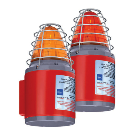
Funktion und Geräteaufbau Funktion und Geräteaufbau WARNUNG Gefahr durch zweckentfremdete Verwendung! Explosionsschutz gefährdet! • Gerät ausschließlich entsprechend den in dieser Betriebsanleitung fest- gelegten Betriebsbedingungen verwenden. Funktion Das explosionsgeschützte optische Signalgerät der Reihe FL 60 liefert ein optisches Blinksignal das zur Alarmierung Warnung oder als Hinweis auf ein Ereignis vorgesehen ist. - Page 9 Technische Daten Explosionsschutz Europa (ATEX) Gas und Staub IIB+H2 Baseefa02ATEX0222X Baseefa02ATEX0212X IIB+H2, IIB EN 60079-0: 2009 / EN 60079-1: 2007 / EN 60079-31: 2009 IIB+H2 EII 2 GD Ex d IIB+H2 T4 Gb (Ta = -20 … +60 °C) EII 2 GD Ex tb IIIC T135°C Db IP 66 (Ta = -20 … +60 °C) EII 2 GD Ex d IIB+H2 T6 Gb (Ta = -20 …...
-
Page 10: De Technische Daten
Technische Daten Technische Daten Elektrische Daten Bemessungsbe- 24 V DC or 48 V DC, 115 V AC or 230 V AC operational parameters + or -10 % triebsspannung Bemessungsbe- 24 V DC 220 mA triebsstrom 10 J 500 mA 20 J 1100 mA 48 V DC 135 mA... -
Page 11: De 6 Transport Und Lagerung
20 J Blitzenergie 5, 10 or 20 J Blitzfrequenz 60 Blitze pro Minute Weitere technische Daten, siehe www.stahl-ex.com. Transport und Lagerung • Gerät nur in Originalverpackung transportieren und lagern. • Gerät trocken (keine Betauung) und erschütterungsfrei lagern. • Gerät nicht stürzen. -
Page 12: De De
Montage und Installation Montage und Installation Maßangaben / Befestigungsmaße Maßzeichnung (alle Maße in mm [Zoll]) - Änderungen vorbehalten 145 mm / 5.7 ” 13978E00 Montage / Demontage, Gebrauchslage GEFAHR Explosionsgefahr! Gefahr von Verletzungen und Sachschäden! • Bei Verwendung von Aderendhülsen müssen diese unbedingt gasdicht mit geeignetem Werkzeug angebracht werden. - Page 13 Montage und Installation 7.2.1 Einbaubedingungen Netzanschluss GEFAHR Explosionsgefahr! Gefahr von Verletzungen und Sachschäden! • Es dürfen nur Kabel- und Leitungseinführungen mit entsprechender Zertifizierung verwendet werden. Diese müssen zünddurchschlagsicher (Ex d) und für die jeweils verwendete Kabelart geeignet sein sowie die Anforderungen der IEC/EN 60079-14 erfüllen.
- Page 14 Montage und Installation 7.2.3 Zusammenbau des Gehäuses • Bei getrennten Leitungen die Leiterplatte wieder vorsichtig in das Gehäuse einsetzen, bis sie sich in der richtigen Position befindet. • Darauf achten, dass die Blitzröhre gut sichtbar ist und sich mittig in der Glashaube be- findet.
- Page 15 Montage und Installation 16443E00 Schlüsselkomponenten FL60 DC, AC (10J, 20J) Legende 1 = Reihenklemmen Kabelanschluss • Es werden ca. 20 cm (8 Inch) Kabelschwanz zum Anschluß der Klem- men an die Leiterplatte im Gehäuse benötigt. Dies ist insbesondere bei der Installation mit eindrähtigen Leitern zu beachten. Beim Wiederein- setzen der Leiterplatte vorsichtig vorgehen.
-
Page 16: Installation
Montage und Installation AC Ausführung 15260E00 16438E00 16434E00 FL60 AC 5 J FL60 AC 5 J FL60 AC10/20 J Anschluss für Telefo- nanlagen Blitzleuchte Erde Anschluss für Telefonanlagen 7.2.5 Erdanschluss • Die FL60 muss mit einem qualitativ hochwertigen Erdungsanschluss ver- sehen sein. - Page 17 Inbetriebnahme GEFAHR Explosionsgefahr! Gefahr von Verletzungen und Sachschäden! • Das Gerät nur in unbeschädigtem Zustand betreiben. • Bei beschädigtem Gewinde ist das Gerät sofort auszutauschen. • Bei Handhabung des Geräts und der Bauelemente ist mit höchster Sorgfalt vorzugehen. • Mit besonderer Sorgfalt ist beim Anschluss der Leiterplatte vorzugehen. •...
-
Page 18: De Betrieb
Tritt ein Fehler auf, lesen Sie bitte die vorherigen Abschnitte dieses Dokuments. Wenn sich der Fehler mit den genannten Vorgehensweisen nicht beheben lässt: • An die nächste Vertriebsniederlassung der R. STAHL Schaltgeräte GmbH wenden. Zur schnellen Bearbeitung folgende Angaben bereithalten: •... -
Page 19: 10.3 Reparatur
10.3 Reparatur GEFAHR Gefahr durch unsachgemäße Wartung/Reparatur! Explosionsschutz gefährdet! • Reparaturen an den Geräten dürfen ausschließlich durch R. STAHL Schaltgeräte GmbH ausgeführt werden. 10.4 Rücksendung Für die Rücksendung im Reparatur-/Servicefall das Formular "Serviceschein" verwen- den. Auf der Internetseite "www.stahl-ex.com" im Menü "Downloads > Kundenservice": •... - Page 21 Operating instructions Additional languages www.stahl-ex.com Explosion Proof Visual Signal 5, 10 or 20 Joule Series FL60...
- Page 22 10.3 Repair .......................16 10.4 Returning the Device ..................16 Cleaning ......................16 Disposal ......................16 Accessories and Spare Parts ................17 General Information Manufacturer R. STAHL Schaltgeräte GmbH R. STAHL Schaltgeräte GmbH Kompetenzcenter Licht Nordstr. 10 Am Bahnhof 30 99427 Weimar 74638 Waldenburg Germany...
-
Page 23: Information Regarding The Operating Instructions
• 60079-1:2007-04, Edition 6.0 • 60079-31:2008, Edition 1.0 • 60947-1:2007 + A1:2011 • 61000-6-3:2001 Additional standards: See certificates and EC Declaration of Conformity: www.stahl-ex.com. Explanation of the Symbols Symbols in these Operating Instructions Symbol Meaning Tips and recommendations on the use of the device... -
Page 24: En 2.2 Warning Notes
Safety Notes Warning Notes Warning notes must be observed under all circumstances, in order to minimize the risk due to construction and operation. The warning notes have the following structure: • Signalling word: DANGER, WARNING, CAUTION, NOTICE • Type and source of danger/damage •... -
Page 25: En 3.2 Safe Use
Function and Device Design Safe use • Read and observe the safety notes in these operating instructions! • Use the device in accordance with its intended and approved purpose only! • We cannot be held liable for damage caused by incorrect or unauthorized use or by non-compliance with these operating instructions. -
Page 26: En Technical Data
Technical Data Technical Data Explosion protection Global (IECEx) Gas and dust IIB+H2 IECEx BAS 05.0087X IECEx BAS 05.0086X IIB+H2, IIB IEC 60079-0: 2011 / IEC 60079-1: 2007-04 / IEC 60079-31: 2008 IIB+H2 Ex d IIB+H2 T4 Gb (Ta = -20 … +60°C) Ex tb IIIC T135°C Db IP 66 (Ta = -20 …... - Page 27 Technical Data Technical data Product weight 5.08 kg Electrical data Rated operational 24 V DC or 48 V DC, 115 V AC or 230 V AC voltage operational parameters + or -10 % Rated operational 24 V DC 220 mA current 10 J 500 mA...
-
Page 28: En 6 Transport And Storage
5, 10 or 20 J Flash rate 60 FPM For further technical data, see www.stahl-ex.com. Transport and Storage • Transport and store the device only in the original packaging. • Store the device in a dry place (no condensation) and vibration-free. - Page 29 Mounting and Installation 7.2.1 Installation Conditions for Electrical Connection DANGER Risk of explosion! Risk of injuries and material damage! • Only cable glands with a corresponding certificate may be used. They must be flameproof (Ex d), suitable for the type of cable used and fulfil the requirements of IEC/EN 60079-14.
- Page 30 Mounting and Installation • Correct reassembly of the FL60 is required to ensure ingress protection to IP 66. Cheese-head screws (see chapter Acess to the PCB, position 3) are supplied with Nyltite washers. Before reassembly inspect Nyltite for damage and check orientation is correct as per diagram. •...
- Page 31 Mounting and Installation Cable Connection • Approximately 20 cm (8 Inch) tails are required inside the enclosure for connection to the terminals on the PCB. This is especially important for installation using solid core cable. Care is needed when re-inserting the PCB.
-
Page 32: Installation
Mounting and Installation AC versions 15260E00 16438E00 16434E00 FL60 AC 5 J FL60 AC 5 J FL60 AC10/20 J telephone initiate Strobe Earth Telephone Initiate 7.2.5 Earth Connection • FL60 must be connected to a good quality earth. • The internal Earth connection is the primary point. - Page 33 Commissioning DANGER Risk of explosion! Risk of injuries and material damage! • Operate the device only if it is not damaged. • If the thread is damaged, the device must be replaced immediately. • Take extreme care when handling the device and internal components.
-
Page 34: En Operation
If an error occurs please re-visit the earlier sections of this document. If the error cannot be eliminated using the mentioned procedures: • Contact the local representative of R. STAHL Schaltgeräte GmbH. For fast processing, have the following information ready: •... -
Page 35: 10.3 Repair
• Ensure environmentally friendly disposal of all components according to the statutory regulations. Accessories and Spare Parts NOTICE Use only original accessories and spare parts by R. STAHL Schaltgeräte GmbH. For accessories and spare parts, see data sheet on our homepage www.stahl-ex.com. 223845 / FL6060300010 Explosion Proof Visual Signal 5, 10 or 20 Joule 2014-10-16·BA00·III·en·00...
Need help?
Do you have a question about the FL60 Series and is the answer not in the manual?
Questions and answers