
Subscribe to Our Youtube Channel
Related Manuals for Stahl EXLUX 6009/5 Series


Summary of Contents for Stahl EXLUX 6009/5 Series
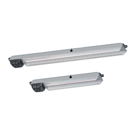
- Page 1 Operating instructions Additional languages r-stahl.com Emergency luminaire for fluorescent lamps Series EXLUX 6009/5...
-
Page 2: Table Of Contents
Contents General Information ....................3 Manufacturer .......................3 Information regarding the operating instructions ..........3 Further documents ....................3 Conformity with standards and regulations ............3 Explanation of the symbols .................4 Symbols in these operating instructions .............4 Warning notes .....................4 Symbols on the device ..................5 Safety notes ......................5 Operating instructions storage ................5 Safe use ......................5... -
Page 3: En En
• Data sheet For documents in additional languages, see r-stahl.com. Conformity with standards and regulations See certificates and EU Declaration of Conformity: r-stahl.com. The device has IECEx approval. For certificate please refer to the IECEx homepage: http://iecex.iec.ch/ Further national certificates can be downloaded via the following link: https://r-stahl.com/en/global/support/downloads/. -
Page 4: Explanation Of The Symbols
Explanation of the symbols Explanation of the symbols Symbols in these operating instructions Symbol Meaning Tips and recommendations on the use of the device Danger due to explosive atmosphere Danger due to live components Warning notes Warnings must be observed under all circumstances, in order to minimize the risk due to construction and operation. -
Page 5: Symbols On The Device
• Use the device in accordance with its intended and approved purpose only. • Always consult R. STAHL Schaltgeräte GmbH if using the device under operating conditions which are not covered by the technical data. • We cannot be held liable for damage to the device caused by incorrect or unauthorised use or non-compliance with these operating instructions. -
Page 6: 3.3 Intended Use
Function and device design Intended Use The luminaire 6009/5 is equipment • for lighting areas, work spaces and objects • for emergency lighting in case of power failure. • can be used indoors and outdoors • for stationary mounting • for use in Zones 1, 21, 2, 22 and in the safe area Modifications and alterations DANGER Explosion hazard due to modifications and alterations to the device! -
Page 7: Device Design
Function and device design Device design 16385E00 Lamp holder Light fitting enclosure Control gear Reflector plate Translucent cover Battery Cable entry Battery enclosure Connection terminal 226311 / 600960300010 Emergency luminaire for fluorescent lamps 2020-04-17·BA00·III·en·04 Series EXLUX 6009/5... -
Page 8: Technical Data
Technical data Technical data Explosion Protection Global (IECEx) Gas and dust IECEx PTB 13.0059 Ex db eb mb IIC T4 Gb Ex tb IIIC T80 °C Db Europe (ATEX) Gas and dust PTB 13 ATEX 2015 E II 2 G Ex db eb mb IIC T4 Gb E II 2 D Ex tb IIIC T80 °C Db Certifications and certificates Certificates... - Page 9 Technical data Technical Data Power factor Voltage Lamp standard Power factor 230 V IEC 60081 ≥ 0.93 110 V IEC 60081 ≥ 0.97 120 V ANSI IEC C78.81 ≥ 0.97 Voltage Lamp standard Size 2 Size 4 230 V IEC 60081 11.9% 10.8% 110 V...
- Page 10 Technical data Technical Data Mechanical data Degree of protection IP66 / IP67 (IEC 60598) IP64 if a breather is used Impact strength IK10 (IEC 62262) (IK code) Material Enclosure Polyester resin, glass fibre reinforced Enclosure colours Grey colour, similar to RAL 7035 Lamp cover Polycarbonate Seal...
- Page 11 The battery set can be replaced after disconnecting the plug-in contacts. Optional Breather Breather 8162/1 from R.STAHL Schaltgeräte GmbH The breather guarantees compliance with degree of protection IP64 in all mounting positions. The breather may not be used in atmospheres with corrosive gases.
-
Page 12: Engineering
Engineering Engineering Mains operation 6.1.1 Stand-by operation • The light fitting is switched off. L´ PE N 16397E00 6.1.2 Continuous operation • The light fitting is switched on. L´ PE N 16398E00 6.1.3 Normal lighting operation • The light fitting is operated by normal lighting. L´... -
Page 13: Emergency Light Blocking
Engineering Emergency light blocking A remote switch for emergency light blocking can be connected to terminals 9 and 10 of the control gear. LED green LED grün LED red LED rot mit Brücke ohne Brücke 1,5 h with jumper without jumper Fernschalter Remote switch Fernschalter... - Page 14 Engineering Linear connection 18473E00 The following conductor specifications must be observed during connection. Point-to-point connection Linear connection maximum conductor length 500 m 100 m 50 m 500 m maximum number of light fittings 50 Cable cross section 1.5 mm 1.5 mm Emergency luminaire for fluorescent lamps 226311 / 600960300010 Series EXLUX 6009/5...
-
Page 15: 7 Transport And Storage
Transport and storage Transport and storage General • Transport and store the device only in the original packaging. • Store the device in a dry place (no condensation) and vibration-free. • Do not drop the device. Batteries • Do not transport together with other materials. •... -
Page 16: 8.1 Dimensions / Fastening Dimensions
Mounting and installation Dimensions / fastening dimensions Dimensional drawings (all dimensions in mm [inches]) – Subject to modification 183,5 [7,22] M25 x 1,5 M25 x 1,5 16127E00 Dimen- Light fitting sions Size 2 Size 4 857 [33.74] 1467 [57.76] 400 [15.75] 800 [31.50] 320 to 480 [12.60 to 18.90] 670 to 930 [26.38 to 36.61]... - Page 17 Mounting and installation Dimensional drawings for assembly parts and accessories (all dimensions in mm) – Subject to alterations 15782E00 15781E00 15783E00 Ring bolt fitted Mounting bracket Pipe clamp fitted in insert nut of fitted in mounting in mounting rail the luminaire rail 15780E00 Wall mounting bracket...
-
Page 18: Mounting / Dismounting, Operating Position
Mounting and installation Mounting / dismounting, operating position DANGER Explosion hazard due to electrostatic discharge! Non-compliance results in severe or fatal injuries. Do not use the luminaire in strong charge generating environments! The following processes/activities should be avoided: • accidental friction •... - Page 19 Mounting and installation Suspension at movable mounting parts 16325E00 16326E00 Mounting bracket Top rail Size L4 mm [inch] L mm [inch] 320 [12.60] 80 [3.15] 670 [26.38] 130 [5.12] Lateral mounting pockets for variable points of suspension. When mounting the luminaire using top rails, ensure that the mounting surface is flat.
- Page 20 80 [3.15] 670 [26.38] 130 [5.12] For pipe clamp mounting, use the solution of R. STAHL Schaltgeräte GmbH with integrated mounting rail providing reliable and stable four-point fixing! In case of point suspension using pipe clamps, R. STAHL Schaltgeräte GmbH does not guarantee the strength and...
- Page 21 / 26,38 ... 36,61 " 32 16334E00 R. STAHL Schaltgeräte GmbH - rail profile for continuous row mounting of linear luminaires EXLUX The rail profile facilitates row mounting and installation of the luminaires. The rail profile can also be used as a cable duct.
-
Page 22: Installation
(see information plate on the lock)! Recommendation Opening and closing of the luminaire by using a socket wrench from R. STAHL Schaltgeräte GmbH. • Remove the closing cap of the central lock. • Turn the central lock using a box spanner M8, spanner size 13, by 90°... - Page 23 Mounting and installation Opening and closing the reflector plate Opening: • Open the reflector plate by pressing down on the safety latch (1). • Swivel down the reflector plate (2). Closing: • Flip up the reflector plate 15512E00 and snap it into place. Opening and closing the battery case Opening: •...
- Page 24 Mounting and installation 8.3.2 Electrical connections Electrical connection Observe the maximum clamping possibility of the connecting terminals (see chapter "Technical data"). Observe the following when connecting to the main supply: • Clamping must be carried out precisely! • Do not clamp any part of the conductor insulation! •...
- Page 25 Mounting and installation Through wiring of the mains supply connection Through wiring with 2.5 mm cross section for max. 16 A. Battery connection The connection to the battery is interrupted. Before commissioning, connect the battery. NOTICE Deep battery discharge due to non-utilisation. Non-compliance may lead to material damage! •...
- Page 26 The standard luminaire is delivered with 3 lead-in holes, 2 cable glands and 2 stopping plug. Tightening torques for components from R. STAHL Schaltgeräte GmbH Luminaires with installed cable entries and stopping plugs from R. STAHL Schaltgeräte GmbH must be tightened using the following values: Tightening torque Connection thread Pressure screw Cable entry M20 x 1.5...
-
Page 27: Commissioning
Commissioning Commissioning DANGER Explosion hazard due to incorrect installation! Non-compliance results in severe or fatal injuries. • Check the device for proper installation before commissioning. • Comply with national regulations. NOTICE Malfunction or device damage caused by condensation. Non-compliance can result in material damage! •... -
Page 28: 10 Operation
Operation Operation 10.1 Operating Modes Power supply operation: Stand-by switching The luminaire is switched off regardless of normal lighting. Continuous mode The luminaire is switched on regardless of normal lighting. Normal lighting operation The light fitting is operated by normal lighting. Emergency light operation: In the event of a power failure, the luminaire switches to emergency light operation. -
Page 29: Functional And Rated Operating Time Test
Operation Emergency light blocking A remote switch for emergency light blocking can be connected to terminals 9 and 10 of the control gear. LED green LED grün LED red LED rot mit Brücke ohne Brücke 1,5 h with jumper without jumper Fernschalter Remote switch Fernschalter... -
Page 30: Indications
Operation 10.3 Indications When connecting to the power supply Initialisation within 30 seconds Seconds Description 0 to 10 Function test green LED 10 to 20 Function test red LED 20 to 30 Status of rated operating time test Green LED flashes - rated operating time test active Red LED flashes - rated operating time test active Then, the LED indicator switches to operating mode. -
Page 31: Troubleshooting
The battery capacity is too low. Replace the battery. If the error cannot be eliminated using the mentioned procedures: • Contact R. STAHL Schaltgeräte GmbH. For fast processing, have the following information ready: • Type and serial number of the device •... -
Page 32: Maintenance, Overhaul, Repair
Maintenance, Overhaul, Repair Maintenance, Overhaul, Repair CAUTION Risk of electric shock or malfunction of the device due to unauthorized work! Non-compliance can result in light injuries! • Before carrying out work on the device, switch off voltage supply. • Work performed on the device must only be carried out by authorized and appropriately trained qualified electricians. - Page 33 Maintenance, Overhaul, Repair 11.1.1 Replacement of lamps Only use fluorescent lamps with pins made of brass. • Insert both lamp bases of the lamp into the holder slots as far as possible. • Turn the lamp clockwise or anticlockwise to bring it into the operating position.
- Page 34 Maintenance, Overhaul, Repair 11.1.2 Replacing the luminaire cover • Open the luminaire. • Swivel the translucent cover backwards by 180°. • Lift the translucent cover to 180° 06058E00 detach it from the hinge. • Insert new translucent cover into the hinge. •...
- Page 35 Maintenance, Overhaul, Repair 16387E00 Screws Battery plug Battery cover Battery Strap Switch • Loosen the screws (1) (cross head H2) in the battery cover (2). • Open the battery case. • The switch (6) disconnects the battery circuit. • Secure the battery cover with installed battery to your wrist using the strap (3). 226311 / 600960300010 Emergency luminaire for fluorescent lamps 2020-04-17·BA00·III·en·04...
- Page 36 Maintenance, Overhaul, Repair 16406E00 • Remove the battery plug from the chamber. • Disconnect the battery plug (4). • Take off the battery cover with installed battery (5). • Put on and secure the battery cover with installed battery (5). •...
-
Page 37: Repair
• Only return or package the devices after consulting R. STAHL! Contact the responsible representative from R. STAHL. R. STAHL's customer service is available to handle returns if repair or service is required. • Contact customer service personally. • Go to the r-stahl.com website. -
Page 38: Cleaning
Accessories and Spare parts NOTICE Malfunction or damage to the device due to the use of non-original components. Non-compliance can result in material damage. • Use only original accessories and spare parts from R. STAHL Schaltgeräte GmbH. Figure Description Art. no. Weight Battery set Battery cover with built-in battery.
Need help?
Do you have a question about the EXLUX 6009/5 Series and is the answer not in the manual?
Questions and answers