
Subscribe to Our Youtube Channel
Related Manuals for Stahl EXLUX 6409/1 Series


Summary of Contents for Stahl EXLUX 6409/1 Series
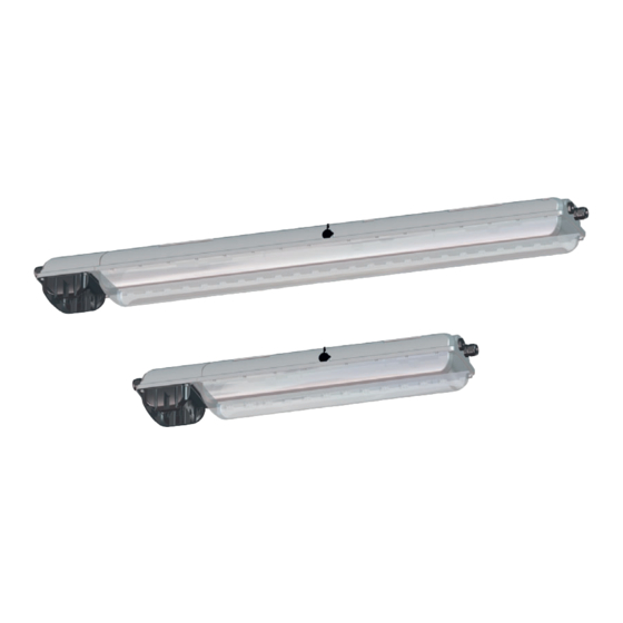
- Page 1 Operating instructions Additional languages www.stahl-ex.com Emergency Luminaire with LED Series EXLUX 6409/1...
-
Page 2: Table Of Contents
Contents General Information ....................3 Manufacturer .......................3 Information regarding the operating instructions ..........3 Further documents ....................3 Conformity with standards and regulations ............3 Explanation of the symbols .................4 Symbols in these operating instructions .............4 Warning notes .....................4 Symbols on the device ..................5 Safety notes ......................5 Operating instructions storage ................5 Safe use ......................5... -
Page 3: General Information
• Data sheet For further languages, see www.stahl-ex.com. Conformity with standards and regulations See certificates and EU Declaration of Conformity: www.stahl-ex.com. The device has IECEx approval. See IECEx homepage: http://iecex.iec.ch/ Further national certificates can be downloaded via the following link: http://www.r-stahl.com/downloads/certificates.html. -
Page 4: Explanation Of The Symbols
Explanation of the symbols Explanation of the symbols Symbols in these operating instructions Symbol Meaning Tips and recommendations on the use of the device General danger Danger due to explosive atmosphere Danger due to energised parts Warning notes Warning notes must be observed under all circumstances, in order to minimize the risk due to construction and operation. -
Page 5: Symbols On The Device
Safety notes Symbols on the device Symbol Meaning CE marking according to the currently applicable directive. 05594E00 According to marking, device approved for hazardous areas. 02198E00 Safety notes Operating instructions storage • Read the operating instructions carefully. • Store the operating instructions at the mounting location of the device. •... -
Page 6: Function And Device Design
Function and device design Function and device design Function DANGER Explosion hazard due to improper use! Non-compliance results in severe or fatal injuries. • Use the device only in accordance with the operating conditions described in these operating instructions. • Use the device only for the intended purpose specified in these operating instructions. - Page 7 Function and device design 18638E00 - Translucent cover - Luminaire enclosure - Control gear - Battery enclosure - Battery - Mounting plate (top side) - Cable gland 10 - LED PCB - Connection terminal 11 - Diffuser - Mounting plate (bottom side) 12 - LED indicator 260520 / 640960300090 Emergency Luminaire with LED...
-
Page 8: Technical Data
Technical data Technical data Explosion Protection Global (IECEx) Gas and dust IECEx IBE 16.0047 Ex dc ec IIC T4 Gc Ex tc IIIC T100°C Dc Ex tb op is IIIC T100°C Db Europe (ATEX) Gas and dust IBExU 16 ATEX 1233 E II 3 G Ex dc ec IIC T4 Gc E II 3 D Ex tc IIIC T100°C Dc E II 2 D Ex tb op is IIIC T100°C Db... - Page 9 Technical data Technical Data Luminous characteristics Power consumption [W] Colour rendering [CRI] ) 80 ) 80 ) 70 ) 70 Colour temperature [K] 5,000 5,000 5,700 5,700 without diffuser Luminous flux [lm] typ. 3,100 typ. 6,200 typ. 3,400 typ. 6,800 Luminaire efficacy [lm/W] typ.
- Page 10 Technical data Technical Data Ambient conditions Ambient temperature without through wiring (1, 2) -20 ... +60 °C with through wiring; I ( 10 A (1, 2) -20 ... +55 °C with through wiring; I ( 16 A -20 ... +50 °C Rated operating time during emergency light operation is guarenteed within an ambient temperature range of -5 …...
- Page 11 Technical data Technical Data Through wiring Through wiring Standard luminaire Luminaires are equipped with internal through wiring. Ingoing and outgoing leads can be connected to the opposite sides. Terminals: see techn. data Wiring cross section: 2.5 mm for max. 16 A. without Optional On the connection side, there are 2 cable entries M25 x 1.5...
-
Page 12: Engineering
Engineering Engineering Mains operation 6.1.1 Stand-by operation • The light fitting is switched off. L´ PE N 16397E00 6.1.2 Continuous operation • The light fitting is switched on. L´ PE N 16398E00 6.1.3 Normal lighting operation • The light fitting is operated by normal lighting. L´... -
Page 13: Emergency Light Blocking
Engineering Emergency light blocking A remote switch for emergency light blocking can be connected to terminals „Remote- switch“ of the control gear. 19192E00 Remote switch is closed Remote switch is opened Power supply Switching on the luminaire Switching on the luminaire operation depending on operation mode depending on operation mode... -
Page 14: En 7 Transport And Storage
Transport and storage Linear connection 18473E00 The following conductor specifications must be observed during connection. Point-to-point connection Linear connection maximum conductor length 500 m 100 m 50 m 500 m maximum number of light fittings Cable cross section 1.5 mm 1.5 mm Transport and storage General... -
Page 15: Mounting And Installation
Mounting and installation Mounting and installation DANGER Explosion hazard due to incorrect installation of the device! Non-compliance results in severe or fatal injuries. • Carry out installation strictly according to the instructions and national safety and accident prevention regulations to maintain the explosion protection. - Page 16 Mounting and installation Dimensional drawings for assembly parts and accessories (all dimensions in mm [inches]) - Subject to alterations 215 8.46 215 [ 193 - 198 [7,60 - 7,80] 15779E00 124 4 88 11 [ , 0 43 86 [ , 3 39 74 [ , 2 91...
-
Page 17: Mounting / Dismounting, Operating Position
Mounting and installation Dimensional drawings for assembly parts and accessories (all dimensions in mm [inches]) - Subject to alterations 200 [7,87] [3,15] 146 [5,75] 15780E00 03257E00 Wall mounting bracket Bracket for wall mounting with fitted in mounting rail pipe section 17756E00 Dimen- Luminaire... - Page 18 Mounting and installation The luminaire is suitable for wall and ceiling mounting. In event of wall mounting in outdoor areas, avoid installation with central lock at top. The mounting position with upward light emission in outdoor areas is prohibited. DANGER Explosion hazard due to inadmissible heating! Non-compliance results in severe or fatal injuries.
- Page 19 Mounting and installation When mounting the luminaire using top rails, ensure that the mounting surface is flat. Otherwise, the enclosure might be mounted in a warped/twisted way. The result is leakage of the luminaire and difficulties in replacing the translucent cover. Pole mounting using pole mounting sleeve 18483E00 18482E00...
- Page 20 L [mm] 28 W 52 W For pipe clamp mounting, use the solution of R. STAHL Schaltgeräte GmbH with integrated mounting rail providing reliable and stable four-point fixing! In case of point suspension using pipe clamps, R. STAHL Schaltgeräte GmbH does not guarantee the strength and tightness of the luminaire!
-
Page 21: Installation
• Luminaires without switch must not be opened when they are supplied with power (see information plate on the lock)! Recommendation Opening and closing of the luminaire by using a socket wrench from R. STAHL Schaltgeräte GmbH. 90° 165° 15451E00... - Page 22 Mounting and installation Opening and closing the reflector plate 1 Open the reflector plate by pressing the safety latch. 2 Swivel down the reflector plate. • When closing, flip up the reflector plate and snap it into place. 15512E00 Opening and closing the battery box 16404E00 16405E00 Opening...
- Page 23 Mounting and installation Note: • Clamping must be carried out precisely! • Do not clamp any part of the conductor insulation! • Do not interchange the conductors! • Observe the technical regulations when connecting the conductor! • Clamp the conductor firmly. •...
- Page 24 The standard luminaire is delivered with 3 lead-in holes, 2 cable glands and 2 stopping plug. Please observe the tightening torque for luminaires with installed cable glands and stopping plugs from R. STAHL Schaltgeräte GmbH. Tightening torque Connection thread Pressure screw Cable gland 8161 M20 x 1.5...
-
Page 25: Commissioning
Commissioning Commissioning DANGER Explosion hazard due to incorrect installation! Non-compliance results in severe or fatal injuries. • Check the device for proper installation and function before commissioning. • Comply with the national regulations. Before commissioning, ensure the following: • Check the mounting and installation. •... -
Page 26: En 10 Operation
Operation Operation 10.1 Operating Modes Power supply operation Stand-by operation The luminaire is switched off regardless of normal lighting. Continuous operation The luminaire is switched on regardless of normal lighting. Normal lighting operation The light fitting is operated by normal lighting. Emergency light operation: In the event of a power failure, the luminaire switches to emergency light operation. -
Page 27: Indications
Operation • takes 1 minute. • checks the function of the LEDs and the battery. Rated operating time test • starts within 44 days after commissioning. • is carried out once a year. • checks the function and the operating time of the luminaire during emergency light mode. - Page 28 Operation LED indicator State Description Green Luminaire is ready for operation Blinking green Luminaire is ready for Function and rated operating time test operation activated Error Battery is defective or electric circuit is interrupted Blinking red Error Last function and/or rated operating time test faulty Flashing red Error...
-
Page 29: Maintenance And Repair
Maintenance and repair Maintenance and repair WARNING Risk of electric shock or malfunctioning of the device due to unauthorized work! Non-compliance can result in severe injuries and material damage. • Work performed on the device must only be carried out by appropriately authorized and qualified electricians. - Page 30 Maintenance and repair 11.1.1 Replacing the luminaire cover • Open the luminaire. • Swivel the translucent cover backwards by 180°. • Lift the translucent cover to detach it from the hinge. • Insert new translucent cover into the hinge. 180° •...
- Page 31 Maintenance and repair • Loosen the screws (1) (cross head H2) of the battery cover. • Open the battery case. • The switch (6) disconnects the battery circuit. • Secure the battery cover with built-in battery on the wrist using the strap (3). 16406E00 •...
- Page 32 The LED indicator lights up in green after troubleshooting. If the error cannot be eliminated using the mentioned procedures: • Contact R. STAHL Schaltgeräte GmbH. For fast processing, have the following information ready: • Type and serial number of the device •...
-
Page 33: Returning The Device
Accessories and Spare parts NOTICE Malfunction or damage to the device due to the use of non-original components. Non-compliance can result in material damage. • Use only original accessories and spare parts from R. STAHL Schaltgeräte GmbH. Figure Description Art. no. Weight Battery set Battery cover with built-in battery.
Need help?
Do you have a question about the EXLUX 6409/1 Series and is the answer not in the manual?
Questions and answers