
Related Manuals for Stahl EXLUX 6009/4 Series


Summary of Contents for Stahl EXLUX 6009/4 Series
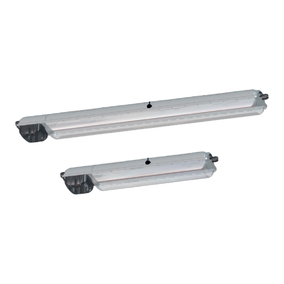
- Page 1 Operating instructions Additional languages www.r-stahl.com Emergency Luminaire with LED Series EXLUX 6009/4...
-
Page 2: Table Of Contents
Contents General Information ....................3 Manufacturer .......................3 Information regarding the operating instructions ..........3 Further documents ....................3 Conformity with standards and regulations ............3 Explanation of the symbols .................4 Symbols in these operating instructions .............4 Warning notes .....................4 Symbols on the device ..................5 Safety notes ......................5 Operating instructions storage ................5 Safe use ......................5... -
Page 3: General Information
General Information General Information Manufacturer R. STAHL Schaltgeräte GmbH R. STAHL (P) LTD., Plot No. - 5 Am Bahnhof 30 Malrosapuram Road, Sengundram Indl. Area 74638 Waldenburg Singaperumal Koil, Kancheepuram Dist., Germany Tamil Nadu – 603 204, INDIA Phone: +49 7942 943-0... -
Page 4: Explanation Of The Symbols
Explanation of the symbols Explanation of the symbols Symbols in these operating instructions Symbol Meaning Tips and recommendations on the use of the device Danger due to explosive atmosphere Danger due to live components Warning notes Warnings must be observed under all circumstances, in order to minimize the risk due to construction and operation. -
Page 5: Symbols On The Device
• Use the device in accordance with its intended and approved purpose only. • Always consult R. STAHL Schaltgeräte GmbH if using the device under operating conditions which are not covered by the technical data. • We cannot be held liable for damage to the device caused by incorrect or unauthorised use or non-compliance with these operating instructions. -
Page 6: En 3.3 Intended Use
Function and device design Intended Use The luminaire 6009/4 is equipment • for lighting areas, work spaces and objects • for emergency lighting in case of power failure. • can be used indoors and outdoors • for stationary mounting • for use in Zones 1, 21, 2, 22 and in the safe area Modifications and alterations DANGER Explosion hazard due to modifications and alterations to the device! -
Page 7: Device Design
Function and device design Device design 20300E00 I.S. Module Cable entry Control gear Connection terminal Translucent cover Luminaire enclosure Battery Battery enclosure 265135 / 600960300190 Emergency Luminaire with LED 2018-11-09·BA00·III·en·00 Series EXLUX 6009/4... -
Page 8: En En
Function and device design 20301E00 LED indicator LED PCB Mounting plate top side Diffuser Emergency Luminaire with LED 265135 / 600960300190 Series EXLUX 6009/4 2018-11-09·BA00·III·en·00... -
Page 9: Technical Data
Technical data Technical data Explosion Protection Global (IECEx) Gas and dust IECEx IBE 16.0038 Ex db eb ib mb op is IIC T4 Gb Ex tb op is IIIC T100°C Db Europe (ATEX) Gas and dust IBExU 16 ATEX 1199 E II 2 G Ex db eb ib mb op is IIC T4 Gb E II 2 D Ex tb op is IIIC T100°C Db Certifications and certificates... - Page 10 Technical data Technical Data Degree of protection IP66 / IP67 (IEC 60598) IP64 if a breather is used Protection class I (with internal PE connection) Impact strength IK10 (IEC 62262) (IK code) Luminous characteristics Colour rendering Ra ) 80 Colour temperature 4,000 K, 5,000 K or 6,500 K depending on the variant Luminous flux Size 2...
- Page 11 Technical data Technical Data Ambient conditions Ambient temperature without through wiring (1, 2) -30 to +60 °C through wiring ( 10 A (1, 2) -30 to +55 °C through wiring ( 16 A -30 to +50 °C Rated operating time during emergency light operation is guaranteed within an ambient temperature range of -5 to +50 °C.
- Page 12 Technical data Technical Data Through wiring Standard with luminaire Luminaries are equipped with internal through wiring. Connection of ingoing and outgoing leads on opposite sites is possible. Terminals: See Tech. data Wiring cross section of the supply line connection: 2.5 mm for max.
-
Page 13: Engineering
DALI interface in accordance with IEC 62386-202:2009-08 and IEC 62386-207:2009-08 Breather Breather 8162/1 from R.STAHL Schaltgeräte GmbH The breather guarantees compliance with degree of protection IP64 in all mounting positions. The breather may not be used in atmospheres with corrosive gasses. -
Page 14: Emergency Light Blocking
Engineering 6.1.3 Normal lighting operation • The light fitting is operated by normal lighting. L´ PE N 16399E00 Emergency light blocking A remote switch for emergency light blocking can be connected to terminals 10 and 12 of the control gear. Sign. - Page 15 Engineering 6.2.1 Connection version remote switch The remote switch is directly connected to the control gear. The following connection versions are possible: Point-to-point connection 18474E00 Linear connection 18473E00 The following conductor specifications must be observed during connection. Point-to-point connection Linear connection maximum conductor length 500 m 100 m...
-
Page 16: En 7 Transport And Storage
Transport and storage Transport and storage General • Transport and store the device only in the original packaging. • Store the device in a dry place (no condensation) and vibration-free. • Do not drop the device. Batteries • Do not transport together with other materials. •... -
Page 17: Dimensions / Fastening Dimensions
Mounting and installation Dimensions / fastening dimensions Dimensional drawings (all dimensions in mm [inches]) – Subject to modification 183,5 [7,22] M25 x 1,5 M25 x 1,5 16127E00 Dimen- Luminaire sions Size 2 Size 4 857 [33.74] 1467 [57.76] 400 [15.75] 800 [31.50] 320 to 480 [12.60 to 18.90] 670 to 930 [26.38 to 36.61]... - Page 18 Mounting and installation Dimensional drawings for assembly parts and accessories (all dimensions in mm [inches]) – Subject to alterations 15782E00 15781E00 15783E00 Ring bolt fitted Mounting bracket Pipe clamp fitted in insert nut of fitted in mounting in mounting rail the luminaire rail 200 [7,87]...
-
Page 19: Mounting / Dismounting, Operating Position
Mounting and installation Mounting / dismounting, operating position DANGER Explosion hazard due to electrostatic discharge Non-complicance results in severe or fatal injuries. Do not use the luminaire in strong charge generating environments! The following processes/activities should be avoided: • accidental friction •... - Page 20 Mounting and installation Suspension at movable mounting parts 16325E00 16326E00 Mounting bracket Top rail Size L4 mm [inch] L mm [inch] 320 [15.60] 80 [3.15] 670 [26.38] 130 [5.12] Lateral mounting pockets for variable points of suspension. When mounting the luminaire using top rails, ensure that the mounting surface is flat.
- Page 21 80 [3.15] 670 [26.38] 130 [5.12] For pipe clamp mounting, use the solution of R. STAHL Schaltgeräte GmbH with integrated mounting rail providing reliable and stable four-point fixing! In case of point suspension using pipe clamps, R. STAHL Schaltgeräte GmbH does not guarantee the strength and...
-
Page 22: Installation
• Open luminaires without switch only in de-energized state (see information plate on the lock)! Recommendation Opening and closing of the luminaire by using a socket wrench from R. STAHL Schaltgeräte GmbH. Emergency Luminaire with LED 265135 / 600960300190 Series EXLUX 6009/4... - Page 23 Mounting and installation • Remove the closing cap of the central lock. • Turn the central lock using a box spanner M8, spanner size 13, by 90° to the left as far as it will go. • Swivel down the translucent cover. •...
- Page 24 Mounting and installation Opening and closing the battery case Opening: • Loosen the screws (1) (cross head H2). • Open the battery cover (2). Closing: • Close the battery cover (2). • Tighten the screws (1) (cross head H2) firmly (2 Nm). 16404E00 16405E00 8.3.2 Electrical connections...
- Page 25 Mounting and installation Connection terminals Clamping range: 1 x 1.5 to 6 mm solid / finely stranded (2 free clamping units per pole available) Stripping length: 10 to 12 mm Standard: L‘ = switched phase = charging phase L‘ L2, L3 = phase = neutral conductor = protective conductor...
- Page 26 The standard luminaire is delivered with 3 lead-in holes, 2 cable glands and 2 stopping plug. Tightening torques for components from R. STAHL Schaltgeräte GmbH Luminaires with installed cable entries and stopping plugs from R. STAHL Schaltgeräte GmbH must be tightened using the following values: Tightening torque Connection thread Pressure screw Cable entry M20 x 1.5...
-
Page 27: Commissioning
Commissioning Please observe the following: • the required dust resistance! • the required type of protection! • the required temperature resistance! • the IP degree of protection according to the rating plate! • the operating instructions of the cable entries and stopping plugs! •... -
Page 28: En 10 Operation
Operation Operation 10.1 Operating Modes Power supply operation: Stand-by operation The luminaire is switched off regardless of normal lighting. Continuous operation The luminaire is switched on regardless of normal lighting. Normal lighting operation The light fitting is operated by normal lighting. Emergency light operation: In the event of a power failure, the luminaire switches to emergency light operation. -
Page 29: Functional And Rated Operating Time Test
Operation Emergency light blocking A remote switch for emergency light blocking can be connected to terminals 10 and 12 of the control gear. Sign. LED (2) Sign. LED (1) Remote switch 18475E00 Remote switch is closed Remote switch is opened Power supply Switching on the luminaire Switching on the luminaire... -
Page 30: Indications
Operation 10.3 Indications When connecting to the power supply Initialisation within 10 seconds Second Description 0 to 2 Function test green LED 2 to 4 Function test red LED 4 to 10 Status rated operating time test Green LED flashes - rated operating time test active Green LED off - rated operating time test not active Then the LED indicator switches to operating mode. -
Page 31: Troubleshooting
The LED indicator lights up in green after troubleshooting. If the error cannot be eliminated using the mentioned procedures: • Contact R. STAHL Schaltgeräte GmbH. For fast processing, have the following information ready: • Type and serial number of the device •... -
Page 32: Maintenance, Overhaul, Repair
Maintenance, Overhaul, Repair Maintenance, Overhaul, Repair CAUTION Risk of electric shock or malfunction of the device due to unauthorized work! Non-compliance can result in light injuries! • Before carrying out work on the device, switch off voltage supply. • Work performed on the device must only be carried out by authorized and appropriately trained qualified electricians. - Page 33 Maintenance, Overhaul, Repair 11.1.1 Replacing the luminaire cover • Open the luminaire. • Swivel the translucent cover backwards by 180°. • Lift the translucent cover to 180° 06058E00 detach it from the hinge. • Insert new translucent cover into the hinge. •...
- Page 34 Maintenance, Overhaul, Repair 16387E00 Screws Battery plug Battery cover Battery Strap Switch • Loosen the screws (1) (cross head H2) in the battery cover (2). • Open the battery case. • The switch (6) disconnects the battery circuit. • Secure the battery cover with installed battery to your wrist using the strap (3). Emergency Luminaire with LED 265135 / 600960300190 Series EXLUX 6009/4...
- Page 35 Maintenance, Overhaul, Repair 16406E00 • Remove the battery plug from the chamber. • Disconnect the battery plug (4). • Take off the battery cover with installed battery (5). • Put on and secure the battery cover with installed battery (5). •...
-
Page 36: Repair
• Only return or package the devices after consulting R. STAHL! Contact the responsible representative from R. STAHL. R. STAHL's customer service is available to handle returns if repair or service is required. • Contact customer service personally. • Go to the www.r-stahl.com website. -
Page 37: Disposal
Accessories and Spare parts NOTICE Malfunction or damage to the device due to the use of non-original components. Non-compliance can result in material damage. • Use only original accessories and spare parts from R. STAHL Schaltgeräte GmbH. Figure Description Art. no. Weight Battery set Battery cover with built-in battery.
Need help?
Do you have a question about the EXLUX 6009/4 Series and is the answer not in the manual?
Questions and answers