
Related Manuals for NORCAL NC2030

Summary of Contents for NORCAL NC2030
- Page 1 Norcal NC2030 Low power, High Performance 20m or 30m DC Transceiver Norcal NC2030 v5 12-18-05 Page 1 of 128...
-
Page 2: Table Of Contents
Add rear panel hardware........................89 Receiver alignment section ........................96 LO Filter tune up..........................96 PTO Frequency Alignment ........................97 PTO tuning for the 20m version (2.941 to 3.006 MHz) ............... 97 Norcal NC2030 v5 12-18-05 Page 2 of 128... - Page 3 RF front end tune up ........................... 100 Opposite sideband suppression ......................102 Setting RX/TX offset .......................... 104 Transmitter Test ............................106 Operating the NC2030 ..........................106 Principles of operation ..........................109 Transceiver Block Diagram ........................ 109 Receiver .............................. 109 T/R switch............................109 Detector/ AF pre-amp ........................
- Page 4 Figure 38. Location of the CW Keyer section of the board..............42 Figure 39. Close up of the CW Keyer section..................42 Figure 40. Picture showing correct orientation of Norcal Keyer Chip (optional socket not shown) ..43 Figure 41. General Location of AFA circuit..................... 44 Figure 42.
- Page 5 ............................. 68 Figure 83. General location of the Detector and Front End Filter ............70 Figure 84. Close up of the detector and the RF tuned front end............... 70 Norcal NC2030 v5 12-18-05 Page 5 of 128...
- Page 6 Figure 100. Location of R95 and R96. Voltages on transmit/receive switches........84 Figure 101. Mount all four corners of the main board using the mounting hardware as shown..... 85 Figure 102. NC2030 with all front panel hardware mounted in prototype chassis. Case will be silk screened............................. 85 Figure 103.
- Page 7 Figure 142. Mem + dah menu (PAR mem to exit) ................126 Figure 143. Mem switch menu (PAR mem to advance to the next menu item)........127 Figure 144. Mem + both menu (PAR mem to exit)................127 Norcal NC2030 v5 12-18-05 Page 7 of 128...
-
Page 8: A Bit Of History And Recognition
The NC2030 design attempted to maximize receiver performance give a receiver current drain constraint of roughly 10 ma at 12v. The NC2030 draws roughly 12ma in its current form, while providing 140+ db of blocking dynamic range and 107+ db of third order intercept dynamic range while operating at full receiver sensitivity. - Page 9 Vicki Tayloe my long suffering wife. Thanks for putting up with this project for the last seven years. NC2030 Kit Crew: I do not know who you are (I know Doug was involved), but my hats off to you! Finally, big thanks to Doug Hendricks for encouragement and support all through this saga! Without him, this would not have gotten to this point.
-
Page 10: Specifications
Suggested headphone sensitivity: at least 104 dbm minimum sensitivity (106 to 110 is better) Transmitter 20m: Power Output: ~4w at 12v, ~500 mA current drain; ~5w at 13.8v; ~1.5w at 7v; 30m: Power Output: ~3w at 12v; ~4w at 13.8v Norcal NC2030 v5 12-18-05 Page 10 of 128... - Page 11 Norcal NC2030 v5 12-18-05 Page 11 of 128...
-
Page 12: Building The Kit
- Two 8 pin sockets for the AFA and the keyer chip (optional) - Magnifying headpiece and/or magnifying glass - Cookie sheet (highly recommended for building on top of in order to catch stray parts) Norcal NC2030 v5 12-18-05 Page 12 of 128... -
Page 13: Figure 1. Working Over An Oversized Cookie Sheet Is Highly Recommended To Catch Stray Surface
Figure 2. A temperature controlled soldering helps a lot. 650 to 700 degrees is recommended. Figure 3. A very pointed soldering iron tip is a very big help for small surface mounted components Norcal NC2030 v5 12-18-05 Page 13 of 128... -
Page 14: Parts List
When finished, slide the remainder of the strip back into the bag pocket for storage. Norcal NC2030 v5 12-18-05... -
Page 15: Figure 5. Parts In Bag Pockets Are Accessed Via Slit Cut Into The Packet Just Larger Enough To Get The Part
Below is an example of a bag layout as compared to a real bag. Notice the correspondence of the three single resistor pockets at the top of the real bag compared to the bag layout. Norcal NC2030 v5 12-18-05 Page 15 of 128... -
Page 16: Figure 7. A Sample Bag Pocket Layout Diagram Vs. A Real Bag Of Parts
The only bag diagram not shown below is the hardware bag. That bag contains the screws, nuts, jacks, knobs, switches, connectors, wire, solder, etc. needed in the kit. Norcal NC2030 v5 12-18-05 Page 16 of 128... -
Page 17: Figure 8. Layout Of The Power Supply And The First Three Bags
Figure 8. Layout of the power supply and the first three bags Norcal NC2030 v5 12-18-05 Page 17 of 128... -
Page 18: Figure 9. Layout Of Bags # 3 To # 6
Figure 9. Layout of bags # 3 to # 6 Norcal NC2030 v5 12-18-05 Page 18 of 128... -
Page 19: Figure 10. Contents Of Bags #7 - #9
1 - 100 pf N220 Temperature compensation disc cap 1 - 1N4001 diode 1 - 5K pot plus nut and lock washer (Volume control) 1 - 25K pot with center detent plus nut and lock washer (RIT control) Norcal NC2030 v5 12-18-05 Page 19 of 128... - Page 20 Status 12-12-05: Two other missing parts are being shipped out, five 100 uf capacitors for the main receiver board and a 30 pf trimmer cap. These are being shipped separately and are not included in the above bags. Norcal NC2030 v5 12-18-05 Page 20 of 128...
-
Page 21: Tools And Construction Hints
Lastly, I have had IC pins that look soldered, but are not. This happens when the top of the lead of the part gets soldered, but the solder does not extend to the pad. On my first NC2030, this happened a few times until I figured out a trick to make sure that all pins were properly soldered. - Page 22 In contrast, the NC2030 always operates at full sensitivity. Look for situations that cause your current receiver problems and then, if possible, listen to the same thing on the NC2030. I think you will be pleased in the difference you hear. Pretty good for less than 12 ma of current drain!
-
Page 23: Power Supply
Power Supply Figure 11. Completed Switching PS with Temporary 9v Power Connection and 100 ohm 3.3v Dummy Load Figure 12. Board layout of the switching power supply. Norcal NC2030 v5 12-18-05 Page 23 of 128... -
Page 24: Figure 13. Switching Supply Built Up
Make sure the marking “AANY” (shown on the IC) is mounted in the orientation shown above. U1s markings are both small and faint. Install C1, C3, C5, C7, C9 and C11, 0.1uf capacitors. Install L1, L3, and L4, 47 uH inductors. Norcal NC2030 v5 12-18-05 Page 24 of 128... -
Page 25: Figure 15. Ps With 0.1 Caps, 47 Uh Inductors, Schottky Diodes, And Switching Ic
Install D2 and D3, type SS14 Schottky 1A 40V. Make sure the diodes are installed with the proper orientation! Refer to the diagrams above. The diode band markings are somewhat faintly marked. Figure 16. PS and Electrolytic Caps Polarity Details Norcal NC2030 v5 12-18-05 Page 25 of 128... -
Page 26: Figure 17. L2 Mounting Details
The far two ends of L2 connect to terminal 1 and 2. There are 27 T between terminals 1 and 3, while there are 24 T between 2 and 3. Refer to the picture above for additional detail. Norcal NC2030 v5 12-18-05... -
Page 27: Figure 18. L2 Details. After First 24 Turns, Add A Twisted Loop For Later Center Tap. Add 27 More Turns
The 1N4001 diode is located in the loose hardware bag. Temporarily connect a 100 ohm leaded resistor and 1N4001 diode as show below: Figure 19. Form 1N4001 Diode as Shown Figure 20. 100 ohm Temporary 3v Load Resistor Formed as Shown Norcal NC2030 v5 12-18-05 Page 27 of 128... -
Page 28: Figure 21. 1N4001 Mounted And 9V Battery Clip Connected
The temporary 3v 100 ohm load resistor will stay connected until the main is has enough circuitry to keep the switching supply in regulation. Norcal NC2030 v5 12-18-05 Page 28 of 128... -
Page 29: Switching Regulator Tests
I might also note that after the switching supply is turned on, the current drain will gradually decrease over time, over perhaps a hour’s time. This seems to be a function of the electrolyte on the 100 uf caps setting up and stabilizing over time. Norcal NC2030 v5 12-18-05 Page 29 of 128... -
Page 30: Main Board Temporary Power Connections
Install D1 part number SL44. Pre-tin leads for D1. It does not seem to take solder very readily. Install C4, C5, C6, C135 0.1 uf Install C136, 100 uf capacitor. Double check the black stripe polarity as shown below. Norcal NC2030 v5 12-18-05 Page 30 of 128... -
Page 31: Main Board 3V And 5V Regulators
Figure 25. Close up of power connections on the main board and switching supply, bypass caps, and polarity diode Main Board 3v and 5v Regulators Figure 26. Location of the two 3v and 5v regulator sections Norcal NC2030 v5 12-18-05 Page 31 of 128... -
Page 32: Figure 27. Close Up Of First Two 3V Ldo Regulators
Then place the cap on the pads and heat the cap leads until the solder melts. When both pins are soldered, gently rock the cap to make sure it is completely soldered down. Norcal NC2030 v5 12-18-05 Page 32 of 128... -
Page 33: Figure 29. Location Of The One 3V And Two 5V Ldo Regulator Sections
Figure 29. Location of the one 3v and two 5v LDO regulator sections This is the second set of LDO voltage regulators that need to be installed Norcal NC2030 v5 12-18-05 Page 33 of 128... -
Page 34: Figure 30. Installed Parts For This Section Of Ldo Regulators. Note The Black Band Orientation On The
This 25v cap is physically large compared to the smaller caps used above at C96 and C97. Make sure you use the right cap. These are polarized capacitors, so make sure they are installed with the correct polarization. Norcal NC2030 v5 12-18-05 Page 34 of 128... -
Page 35: 3V And 5V Ldo Regulator Tests
5v regulators. The voltage should measure the same as the battery voltage measured above, roughly 9v. Measure the voltage across C8 on the second set of regulators installed. This is the output of one of the 5v regulators. The voltage should measure 5v. Norcal NC2030 v5 12-18-05 Page 35 of 128... - Page 36 If some regulators read zero volts output, the most likely problem is that the pins on the regulators are not soldered correctly (not soldered or shorted to an adjacent pin). Examine these pins closely. These are very simple (but small) linear regulators! Disconnect the 9v battery supply. Norcal NC2030 v5 12-18-05 Page 36 of 128...
-
Page 37: Hpf, Audio Amp, Mute, Audio Limiter And Headphone Drivers
HPF, Audio Amp, Mute, Audio Limiter and Headphone Drivers Figure 32. SCAF, HPF, Audio Amp, and Headphone driver section of the board Figure 33. HPF, Audio Amp, Headphone Drivers portion Norcal NC2030 v5 12-18-05 Page 37 of 128... -
Page 38: Figure 34. Picture Shows Orientation Of U11 With Stripe On Upper End
R85 - 1M R75, R80 not used C106 C109 C110 C111 C112 C118 - 0.1uf C103 C104 C113 C114 C117 - 22uf Double check polarity! C95 C98 C107 - 100uf Double check polarity! Norcal NC2030 v5 12-18-05 Page 38 of 128... -
Page 39: Audio Section Partial Tests
This section will be tested further after the SCAF and CW Keyer sections are finished. SCAF Variable Low Pass Filter Figure 35. General location of the SCAF circuit Figure 36. Close up component view of the SCAF section of the board. Norcal NC2030 v5 12-18-05 Page 39 of 128... -
Page 40: Scaf And Additional Audio Section Tests
Apply the 9v battery voltage. Check voltage across C105 to makes sure it has 2.9v. Check the voltage across C108 for ~ 1.4v. This should be biased to roughly half of the 2.9v supply voltage. Norcal NC2030 v5 12-18-05 Page 40 of 128... - Page 41 Check the voltage across C95 for ~ 1.4v. This is a large 100 uf cap in the previous audio section. Check the voltage across C98 for ~ 1.4v, a large 100 uf cap in the previous audio section. Disconnect the 9v battery supply. Norcal NC2030 v5 12-18-05 Page 41 of 128...
-
Page 42: Cw Keyer
Figure 39. Close up of the CW Keyer section. Note: The use of a socket for the keyer chip is optional, but strongly recommended to allow the possibility of a keyer chip upgrade. Norcal NC2030 v5 12-18-05 Page 42 of 128... -
Page 43: Figure 40. Picture Showing Correct Orientation Of Norcal Keyer Chip (Optional Socket Not Shown)
Make sure the chip is installed with the correct IC orientation! The correct IC orientation is shown below: Figure 40. Picture showing correct orientation of Norcal Keyer Chip (optional socket not shown) Norcal NC2030 v5 12-18-05 Page 43 of 128... -
Page 44: Audio Frequency Annunciator
Order of installation: If an optional 8 pin socket is used for the SSS chip, install it now. Make sure the socket notch orientation matches with the notch outline on the board. Norcal NC2030 v5 12-18-05 Page 44 of 128... -
Page 45: Adding External Controls For Functionality Tests
Black and White Violet and Grey Brown, Red, and Orange Yellow, Green, and Blue CW button – Black & White 4” length – S3 AFA button – Black & White 4” length – S2 Norcal NC2030 v5 12-18-05 Page 45 of 128... -
Page 46: Figure 44. Connect Buttons Keyer And Afa Buttons S2 And S3 As Shown
Figure 44. Connect buttons keyer and AFA buttons S2 and S3 as shown CW Speed – 100K pot – Black &White 5.5” length – R88 Norcal NC2030 v5 12-18-05 Page 46 of 128... -
Page 47: Figure 45. Prepare R88 100K Cw Speed Pot As Shown. The Left And Middle Terminals Are Connected To
Figure 46. Connect R88 CW speed pot to the R88 pads as shown. Keep black and white in order shown. Paddle Jack – Brown, Red, Orange – 4” length – JP5 Figure 47. Use Brown/Red/Orange wire and connect up the paddle jack in the color order shown. Norcal NC2030 v5 12-18-05 Page 47 of 128... -
Page 48: Figure 48. Attach Paddle Jack To Jp5 Using The Color Order Shown
Figure 49. Use Brown/Red/Orange wire and connect up the headphone jack in the color order shown Figure 50. Connect the headphone jack to JP4 in the color order shown SCAF Pot – 50K pot - Yellow, Green, Blue – 5” length – R83 Norcal NC2030 v5 12-18-05 Page 48 of 128... -
Page 49: Figure 51. Use Yellow/Green/Blue Wire To Connect To R83, The 50K Scaf Pot In The Color Order Shown
Volume Pot – 5K pot - Yellow, Green, Blue – 3” length – R77 Figure 53. Use Yellow/Green/Blue wire to connect to R77, the 5K volume control pot in the color order shown Norcal NC2030 v5 12-18-05 Page 49 of 128... -
Page 50: Figure 54. Connect The 5K Volume Control Pot To The R77 Header Pads In The Color Order Shown
Figure 54. Connect the 5K volume control pot to the R77 header pads in the color order shown Figure 55. All controls attached thus far Norcal NC2030 v5 12-18-05 Page 50 of 128... -
Page 51: Keyer, Afa And Additional Audio Section Tests
(or if a paddle lever is held on power up), the keyer will disable itself and assume an external straight key is being used. The straight key mode is determined each time the keyer (i.e., the transceiver) is turned on. Norcal NC2030 v5 12-18-05 Page 51 of 128... -
Page 52: Vxo And T/R Offset
20m or 30m. The frequency dependant parts will be identified below. U8 (HFC4051), D2 (DL4007), and D3 (DL4007) need to be installed with the proper polarity. These parts are shown installed below to help aid in the correct orientation. Norcal NC2030 v5 12-18-05 Page 52 of 128... -
Page 53: Figure 58. Proper Orientation Of U8, D2, And D3
470 ohm resistor) C54 - 5 pf L5 - 10 uH X1 - 11.059 MHz Crystal 30m only parts: R55 - 10K C54 - 7.5 pf Norcal NC2030 v5 12-18-05 Page 53 of 128... -
Page 54: Figure 59. Yellow/Green/Blue Wire To Connect To R52, The 25K Rit Pot In The Color Order Shown
Figure 60. Connect the 25K RIT pot to the R52 header in the color order shown. Also attach a SPDT switch to S1 This VXO section of the rig will be tested after the completing the next section. Norcal NC2030 v5 12-18-05... -
Page 55: Afa Rf Buffer And Phase Splitter
The RF phase splitter will not be aligned until much later in the receiver section when alignment is performed to null out the opposite sideband. Install the parts in this section in the following order: U9 - 74AHC00D - - Caution! Double check installation polarity as shown below! Norcal NC2030 v5 12-18-05 Page 55 of 128... -
Page 56: Band Specific Parts
(ground end, hot end)! TP3: This is a test point for tuning up the LO filter. Create a loop out of a spare section of component lead and solder it into place. Norcal NC2030 v5 12-18-05 Page 56 of 128... -
Page 57: Vxo And Afa Buffer Tests
1 Hz granularity. 11.059000 MHz would be read out as “11 R 059 R 000”. 11.059 MHz is the 20m VXO crystal frequency, while 13.0 MHz is the 30m VXO Norcal NC2030 v5 12-18-05... - Page 58 600 Hz offset. This series of tests verifies VXO, T/R offset, and AFA circuitry that has been built thus far. Disconnect the 9v battery supply. Disconnect the temporary wire connection installed above! Norcal NC2030 v5 12-18-05 Page 58 of 128...
-
Page 59: Lo Mixer And Pto
LO Mixer and PTO Figure 65. Board Location of the LO mixer and PTO circuitry Figure 66. Close up of the PTO and Mixer section of the board Norcal NC2030 v5 12-18-05 Page 59 of 128... -
Page 60: Figure 67. Pto And Pto/Vxo Mixer Sections As Built
C73 C83 C87 C93 - Not Used L9 - 1.5uH 5% L11 L12 - 100 uH ("101") C90 - 100 pf N220 Disc capacitor – Note: This part is found in the loose hardware bag. Norcal NC2030 v5 12-18-05 Page 60 of 128... -
Page 61: Figure 68. Temporary Soda Straw Pto Coil L13 Connected To The Pto Oscillator Circuit
This is a dummy inductor used to make sure that the PTO oscillator works, and later on that the LO mixer, filtering, and LO amp work as well. If a more normal ¼” diameter straw is used, use 95T. Norcal NC2030 v5 12-18-05 Page 61 of 128... -
Page 62: Figure 69. Anchoring The First Turn Of The Temporary Pto Coil
A hole is made through the straw in order to provide an anchor point for the first turn. Twist off the first turn as shown below. Figure 69. Anchoring the first turn of the temporary PTO coil. Figure 70. Finished temporary PTO coil with 82T. Tie off holes placed on both ends Norcal NC2030 v5 12-18-05 Page 62 of 128... -
Page 63: Figure 71. Mcdonald's Straw Diameter
While we are at this point, we might as well take some time to start work on the real L13 PTO coil as this will take some time (epoxy glue is involved) can be done in the background. L13 - PTO coil 105T # 30 on Kevlar Coil Form Norcal NC2030 v5 12-18-05 Page 63 of 128... -
Page 64: Figure 73. Wrap First Turn On The Pto Coil. Position ¾" Back From Front, Twist Single Turn In Place
Figure 74. First turn is glued (epoxy) into place to make it easier to wrap the rest of the turns When epoxy is used to anchor the first turn into place, double check to make sure it is spaced ¾” inches from the front. Norcal NC2030 v5 12-18-05 Page 64 of 128... -
Page 65: Figure 75. Coil With Completed 105 Turns. Turns Wound Tight And "Shoulder To Shoulder
Vicki (my wife) recommends “Sally Hansen Diamond Strength”. She got this for me at Ulta. It works very well compared to the cheap stuff I used last time. Norcal NC2030 v5 12-18-05 Page 65 of 128... -
Page 66: Figure 77. 2" Brass Screw Cut Back To A Total Length Of 1 ¾ Inches
True Value hardware stores carry both the 2” 6-32 brass screws and matching 6-32 threaded ½” aluminum spacers. The PTO coil assembly will now be set aside until after the main board is mounted into the chassis. Norcal NC2030 v5 12-18-05 Page 66 of 128... -
Page 67: Lo Filter And Lo Amp
LO Filter and LO amp Figure 79. General location of LO Filter and Amp Figure 80. Close up of the LO Filter and Amp components Norcal NC2030 v5 12-18-05 Page 67 of 128... -
Page 68: Figure 81. Lo Filter And Amplifier As Built. Both Trim Caps Must Have Proper Orientation
Figure 82. Coils L6 and L7 are prepared to be mounted surface mount style on the top of the board on the coil holes 20m only parts: C53 - 5 pf C59 - 150 pf Norcal NC2030 v5 12-18-05 Page 68 of 128... -
Page 69: First Time Lo Filter Tune Up
LO amp section or both to bring the detected voltage up to the needed range if it is low. Norcal NC2030 v5 12-18-05... -
Page 70: Quadrature Detector/Front End Filter
The point of this initial tuning is to just make sure things are working and to get the tuning in the right ball park. Quadrature detector/front end filter Figure 83. General location of the Detector and Front End Filter Figure 84. Close up of the detector and the RF tuned front end Norcal NC2030 v5 12-18-05 Page 70 of 128... -
Page 71: Figure 85. Picture Of Detector And Rf Front End With Parts Installed. Note Trim Cap Orientation And Jumper On Jp3
Need horizontal connections, not vertical. See figure 84 or figure 63. R26 R27 - Not used C13 C15 - 0.1 uf C22 C27 C29 C32 - 0.82 uf C33 - Not used C14 - 22 uf L1 - 100uH Norcal NC2030 v5 12-18-05 Page 71 of 128... -
Page 72: Figure 86. Detail On T1. Two Turn # 32 To Pads 1 & 2. Main Winding Connect To Pads 3 & 4
T1 - 19T #26 T37-6 connected across T1 connections T1 3 & 4, plus 2T connected across T1 connections T1 1 & 2 (see picture above); 10” of #26 and 4” of #30 enamel wire Connect the following for both bands: Norcal NC2030 v5 12-18-05 Page 72 of 128... -
Page 73: Detector Tests
Apply 9v and check that all the detector caps ( C22 C27 C29 C32) have 1.5v across them. Using an ohm meter, check that Terminal 2 and 3 of T1 are both shorted to ground. Remove the 9v battery. Norcal NC2030 v5 12-18-05 Page 73 of 128... -
Page 74: Audio Pre-Amp And Audio Phasing
Insert the parts in the following order: U4 - LT6231 – Caution! Make sure the part is installed with the proper polarity as shown below. Solder one pin, then double check the orientation before finishing. Norcal NC2030 v5 12-18-05 Page 74 of 128... -
Page 75: Figure 90. Component Alignment Of U4, And U5. Note C30, R22 Locations
C18 - 0.47 uf X7R C16 - 100 uf 25v - Caution! Make sure the part is installed with the proper polarity as shown above. R8 - 5K trimmer pot R15 R16 - 50K trimmer pot Norcal NC2030 v5 12-18-05 Page 75 of 128... -
Page 76: Audio Pre-Amp And Audio Phasing Tests
Check all four corner pins of U5 - TLV2464. They should all be at ~ 1.5v Disconnect the 9v battery. Main Audio filter Figure 91. General location of the Audio 750 Hz LPF Norcal NC2030 v5 12-18-05 Page 76 of 128... -
Page 77: Figure 92. Close Up Of The 750 Hz Audio Lpf Section
Caution! Make sure the part is installed with the proper polarity as shown below. Solder one pin, then double check the orientation before finishing. Figure 93. Component placement and alignment of U7 and polarization of caps C47, C48, C49 Norcal NC2030 v5 12-18-05 Page 77 of 128... -
Page 78: Main Audio Filter Tests
(like 2v) and the voltage regulators are no longer providing the inter-stage isolation that happens when they regulate. A low voltage is due to high current drain and usually means an IC was installed backwards. Disconnect the 9v battery. Norcal NC2030 v5 12-18-05 Page 78 of 128... -
Page 79: Transmitter
Transmitter Figure 94. General location of the Transmitter section Figure 95. Close up of the transmitter section portion Norcal NC2030 v5 12-18-05 Page 79 of 128... -
Page 80: Figure 96. All Transmitter Parts Except For The Inductors. Note Ts912 Orientation, Bs170 Flat Side
R97 - 18K – Double check parts placement with photo R95, R106 - 22K R112 - 39K R96, R99 - 47K R103 - 75K Q9, Q10, Q12 - BSS123 MOSFET switch Q11, Q15 - FJV3102R Norcal NC2030 v5 12-18-05 Page 80 of 128... -
Page 81: Figure 97. L19 Mounted. 3T Tap Location Shown
L17 - T37-6 13T #24 - 8” of wire L18 - T37-6 11T #24 - 8” of wire 30m only parts: C140 - 47 pf C145, C151 - 180 pf C141 - 330 pf C144, C147, C149 - 470 pf Norcal NC2030 v5 12-18-05 Page 81 of 128... -
Page 82: Transmitter Tests
Since L14 has not been connected yet, there will be no transmitter output, we just want to make sure the transmit signals are working properly. When sending the low speed dashes, make sure the voltages on pin 11, 12, and 13 toggle between 0 and 2.9v. Norcal NC2030 v5 12-18-05 Page 82 of 128... -
Page 83: Figure 99. Location Of U15 Between Afa And Keyer Chips. Test Pins 11, 12, And 13
When sending a series of low speed dashes, pin 11 will toggle between 5v and 2.5v (2.5v is the PA driver high frequency square wave), pin 12 will stay at 1.4v, and pin 13 will vary between 0 and 2.9v. Norcal NC2030 v5 12-18-05... -
Page 84: Figure 100. Location Of R95 And R96. Voltages On Transmit/Receive Switches
The transceiver is now finished. Time to mount the main board in the chassis and begin alignment. Disconnect/remove the temporary switching supply connection (four wires) between the main board and the switching supply in preparation to place the PC board in the case. Norcal NC2030 v5 12-18-05 Page 84 of 128... -
Page 85: Mounting Into The Case
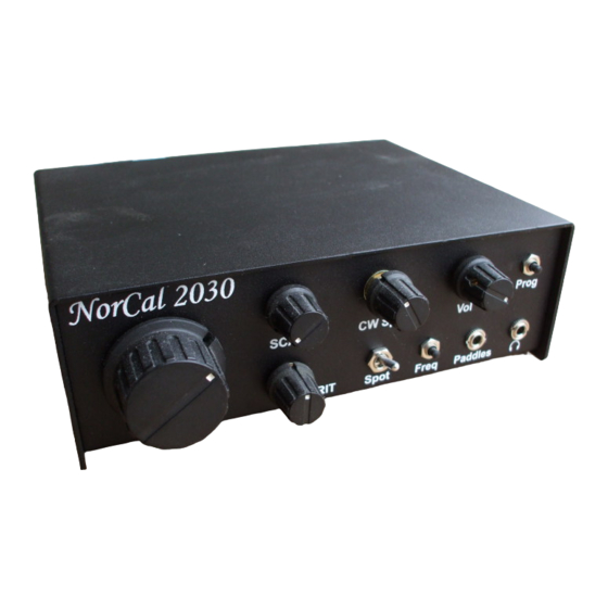
Don’t knock it off! Add front panel hardware Figure 102. NC2030 with all front panel hardware mounted in prototype chassis. Case will be silk screened. Lots of pictures in this section! Here we will mount the hardware to the front panel. -
Page 86: Figure 103. Mount The Paddle Jack
Figure 103. Mount the paddle jack. Figure 104. Mount the headphone jack Norcal NC2030 v5 12-18-05 Page 86 of 128... -
Page 87: Figure 105. Add Keyer Button (Upper Left), Afa Button (Lower Right)
Figure 105. Add Keyer button (upper left), AFA button (lower right) Figure 106. Mount the volume control pot (upper right) and the spot switch (lower middle). Norcal NC2030 v5 12-18-05 Page 87 of 128... -
Page 88: Figure 107. Another View Of The Spot Switch. The Two Terminals Are Orientated In The "Up" Position
“on” if the lever is down, towards the “Spot” label, and off (the normal position) when the switch is up. Figure 108. Add keyer speed pot, SCAF Pot, and RIT pot. Norcal NC2030 v5 12-18-05 Page 88 of 128... -
Page 89: Add Rear Panel Hardware
Add rear panel hardware Figure 109. Rear panel of prototype NC2030. Final case will be silk screened. Figure 110. Antenna jack added Norcal NC2030 v5 12-18-05 Page 89 of 128... -
Page 90: Figure 111. Rear Power Connections: Power Switch, Leads To Rear Switching Supply, Power Jack
Figure 111. Rear power connections: Power switch, leads to rear switching supply, power jack (not shown) Figure 112. Power jack connections, +12v to power switch (red wire) and ground (green) to JP2 ground pad Norcal NC2030 v5 12-18-05 Page 90 of 128... -
Page 91: Figure 113. Placement Of The Switching Supply Tin On The Back Chassis, Power Jack Not Installed
The switching supply tin needs to be mounted on the back side of the radio as shown above. The first step in doing this is placing the switching supply inside the tin, centering it top and bottom, and marking where the two mounting holes need to be drilled in the tin. Norcal NC2030 v5 12-18-05 Page 91 of 128... -
Page 92: Figure 114. Place The Switching Supply Board In The Tin, Center It Top & Bottom, And Mark The Mounting
Next, using the mounting materials, mount the switching supply in the tin using the supplied standoffs, and attach the tin to the back side of the radio. Run the switching supply power cables through the hole and attach them as shown below: Norcal NC2030 v5 12-18-05 Page 92 of 128... -
Page 93: Figure 115. Connect The Power Wires To The Switching Supply In The Color Order Shown
Figure 116. PTO L13 mounting detail. Coil connections shown. Front PTO coil wire must connect as shown. The last component installed is the PTO coil. This coil was wound with extra turns so that the frequency can be trimmed by removing turns. Norcal NC2030 v5 12-18-05 Page 93 of 128... -
Page 94: Figure 117. Connections For The Pto Coil L13
PTO will be glued to. Figure 118. Front side of the PTO coil (prototype chassis) showing epoxy ridge from the front side Norcal NC2030 v5 12-18-05 Page 94 of 128... -
Page 95: Figure 119. Tuning Knob With Pto Screw Partially Inserted
Figure 119. Tuning knob with PTO screw partially inserted. Figure 120. PTO brass screw full inserted into the PTO coil Norcal NC2030 v5 12-18-05 Page 95 of 128... -
Page 96: Receiver Alignment Section
C58 and C60 for the best peak. C60 is the more critical setting of the two caps, so be sure to do tuning sweeps with C60 and incremental changes in C58. Norcal NC2030 v5 12-18-05... -
Page 97: Pto Frequency Alignment
= 11.059 MHz + PTO). The PTO is tuned to the correct frequency simply by removing turns. Warning: Adding the cover to the receiver will increase the final LO frequency by about 2 KHz. Norcal NC2030 v5 12-18-05 Page 97 of 128... -
Page 98: Pto Tuning For The 30M Version (2.850 To 2.900 Mhz)
LO gain boosts that can be done to move the voltage at TP3 into the right range. Norcal NC2030 v5 12-18-05 Page 98 of 128... -
Page 99: Figure 124. Location Of R63, Pto/Vxo Mixer Gain Adjust Located In Bottom Left Corner Of Board
LO filter. Again, the TP3 measurement should be made across the band re-peaking the LO filter caps C58 and C60 peaked for maximum voltage at TP3 mid band. If the voltage is now in the 1 to 1.5v range, we are done. Norcal NC2030 v5 12-18-05 Page 99 of 128... -
Page 100: Rf Front End Tune Up
TP3 will be in the correct range. RF front end tune up Figure 126. Location of RF front end band pass filter adjust trim caps, C23 and C25 on top middle of the board Norcal NC2030 v5 12-18-05 Page 100 of 128... - Page 101 VE3DNL marker generator that Norcal used to sell. One caution: The audio output needs to be kept low enough to keep it from limiting. If the audio is in limiting (0.28v pk-pk or higher), the proper peak might not be seen. Turn down the audio volume as needed.
-
Page 102: Opposite Sideband Suppression
A crystal oscillator loosely coupled into the front end (1 to 2 pf in series). QRP crystals are available from a number of sources including Norcal. A marker generator such as the one available from Norcal. A QRP transmitter transmitting at minimum power into a dummy load produced a very strong signal that can be readily picked up using a 1 inch “sniffer”... -
Page 103: Figure 128. Picture Of Simulated Opposite Sideband Rejection When Optimally Tuned Up
Keep in mind that the audio limiter kicks in at ~0.3v pk-pk or 0.15v peak, or 0.1v RMS so you will not get an audio output larger than this. Norcal NC2030 v5 12-18-05... -
Page 104: Setting Rx/Tx Offset
First locate the trim pot used for the transmit/receive offset, R53, as shown in the picture below. This pot is mounted on the front left hand corner of the board. Norcal NC2030 v5 12-18-05 Page 104 of 128... -
Page 105: Figure 129. Location Of The T/R Offset Trim Pot, R53
The transmitter will only sometimes work down to 6.2v. Even at this voltage, the output power will be over 1w. Norcal NC2030 v5 12-18-05 Page 105 of 128... -
Page 106: Transmitter Test
Operating the NC2030 I am not sure what to say here. The NC2030 appears to operate much the same as a superhet receiver. The NC2030 has a built in keyer, complete with a memory function. The instruction on using the keyer and all of its functions are at the end of this document. - Page 107 LSB as that is how the NC2030 is configured. You should notice immediately the difference in the roll off as a signal goes out of the pass band. The NC2030 pass band is very sharp.
- Page 108 NC2030 has a very stout receiver and handles this situation much better than other radios. The only drawback is that the two operators will be able to hear the VFO of the NC2030 as this is a DC receiver. The LO leakage out the front end has been measured to be -50 dbm (0.00000001 watts). This is not all bad it will not work to have the two transceivers only 500 Hz apart anyway.
-
Page 109: Principles Of Operation
A third MOSFET is used as an inverter to makes sure the series and shunt MOSFETs are turned on and off oppositely from each other. Norcal NC2030 v5 12-18-05 Page 109 of 128... -
Page 110: Detector/ Af Pre-Amp
Some folks have described the detector as a sample and hold device. While this is true in that the detected signal on the detector capacitor is held from one ¼ cycle sample to the next, the actual Norcal NC2030 v5 12-18-05... - Page 111 (10K) divided by the input resistance (100 ohm resistor + 200 ohm detector output). This gives a voltage gain of 33.3. However, the differential input of the detected signal gives another 2x gain to bring the total signal gain to 66.6. Norcal NC2030 v5 12-18-05 Page 111 of 128...
- Page 112 One gain of the “I” audio preamplifier has a fixed gain, while the gain of the other (the “Q” audio preamplifier) has a gain that is variable. The variable gain allows an additional adjustment that is used in the opposite sideband suppression adjustment procedure. Norcal NC2030 v5 12-18-05 Page 112 of 128...
-
Page 113: Phasing Strip
After the phasing strip has been aligned, the opposite side band will be rejected a minimum of 45 db, with much of the bandpass having 50 to 55 db of opposite sideband rejection. The phasing strip has no audio gain. Norcal NC2030 v5 12-18-05 Page 113 of 128... -
Page 114: R/C Audio Filter - Low Pass
Q design. The nine pole Butterworth in the NC2030 has all sections with a Q of three or less, while the alternative Chebychev five pole design would need at least one section with a Q of nine. -
Page 115: R/C Audio Filter - High Pass
AF preamp. The AF preamp gets it bias voltage in turn from the detector itself. In case someone is wondering what happened to the ninth pole in the NC2030 filter, the frequency roll off of the detector is used as the ninth poll. -
Page 116: Audio Amplifier, Mute Switch & Audio Limiter
With the volume at maximum, the diode clipper starts conducting at 280 mV pk-pk at an input RF signal of –95 dbm. The SCAF filter that follows this stage tends to smooth out high frequency Norcal NC2030 v5 12-18-05... -
Page 117: Scaf Variable Low Pass Filter & Headphone Drivers
Butterworth low pass filter. Here it serves to enhance the stop band of the receiver, without introducing ringing. In addition, for very weak signals, the SCAF filter can be lowered in frequency and thus narrow up the receive bandwidth. Norcal NC2030 v5 12-18-05 Page 117 of 128... -
Page 118: Pto Circuit
A 6-32 brass screw is used to tune the inductor. The tuning rate of the PTO is 10 to 12 KHz per turn. As the brass screw is inserted into the inductor, the frequency increases. VXO Circuit (20m - 11.059 MHz, 30m – 13.0 MHz) Figure 136. VXO schematic and transmit/receive offset switching Norcal NC2030 v5 12-18-05 Page 118 of 128... - Page 119 The 20m version of the NC2030 mixes the 3 MHz PTO with the 11.059 MHz VXO output. 11.059 + 3.0 = 14.059 MHz. The VXO provides a small tuning range which is used to provide transmit-receive offset. Half of an 8:1 analog multiplexer is used to select the offset voltage that gets routed to the VXO varactor diodes, which are a pair of inexpensive 1N4007s diodes.
-
Page 120: Lo Mixer And If Filter
11 MHz VXO is several volts pk-pk. The output of the mixer into the filter section is approximately 1.5v pk-pk. LO IF amp and Phase Splitter Figure 138. Schematic of LO amplifier and detector clock phase splitter Norcal NC2030 v5 12-18-05 Page 120 of 128... -
Page 121: Transmitter
E operation. The values listed above are for 20m. Because of the new FCC regulations on harmonic suppression, a seven element low pass filter is used to make sure the transmitter has proper harmonic suppression. Norcal NC2030 v5 12-18-05 Page 121 of 128... -
Page 122: Cw Waveform Shaping
AFA Frequency Counter Instructions Introduction The NC2030 uses an AFA to read out the frequency in morse code and is a modified version of the ScQRPion “Stinger Singer” (a.k.a “SSS”) frequency counter. On power up, the AFA delays (to wait for the keyer chip to send “FB”), then sends “2T3T”... -
Page 123: Mode
The different modes were designed for different reasons. The “E” mode especially short and was intended to be used to read out the frequency of a direct conversion receiver (such as the NC2030). As such, only 100 Hz resolution was desired, and knowledge of the frequency to 99.9 KHz is good enough. -
Page 124: Keyer Instructions
An easy way to do this is to plug in a mono plug from the external key or keyer cable into the stereo paddle jack of the NC2030. The ring contact of the paddle jack will then be grounded. Speed Readout: The speed (in WPM) will be played through the sidetone if the mem switch is simulpressed with the dit switch and then both are released. -
Page 125: Figure 141. Mem + Dit Menu (Par Mem To Advance To The Next Menu Item)
If the pot calibration is run with the pot not set at the minimum, rerun the cal with the pot correctly set. Pressing a Dah will restore the default powerup calibration value. B - Bug / Straight-key mode: Dits are sent normally but dahs are sent like a straight key. Norcal NC2030 v5 12-18-05 Page 125 of 128... -
Page 126: Figure 142. Mem + Dah Menu (Par Mem To Exit)
40th character is sent. The memory is saved in flash memory which means that it will still be there even if power is removed. If this menu item is entered by mistake, PAR the mem switch to exit without changing the memory. Norcal NC2030 v5 12-18-05 Page 126 of 128... -
Page 127: Figure 143. Mem Switch Menu (Par Mem To Advance To The Next Menu Item)
ST - SideTone on/off: Since most rigs have a built-in sidetone, it is handy to be able to silence the NorCal Keyer sidetone, especially when the tone is injected into the rig audio. Note that the sidetone will still be engaged during any menu or recording entry even if it has been turned off. - Page 128 3) powerup the keyer keeping the switch depressed until the FB is sent. One unique feature of the NorCal Keyer is 5 ditdah tune mode. If both paddles are held for at least 5 ditdahs and then released, the keyer will enter tune mode (key down, sidetone on). To exit, tap either the dit or dah.
Need help?
Do you have a question about the NC2030 and is the answer not in the manual?
Questions and answers