Table of Contents
Advertisement
Quick Links
Advertisement
Table of Contents

Related Manuals for golmar EL632/G+/48


Summary of Contents for golmar EL632/G+/48
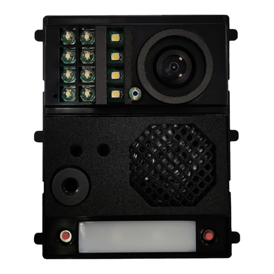
- Page 1 EL632/G+/48 T632/G+/48 IP ML REV.0121...
-
Page 2: Safety And Cautions
EL632/G+/48 IP G+ SAFETY AND CAUTIONS - The installation and handling of this module should be carried out by professional installers. - The current regulations oblige to protect the power supply by means of a thermal magnetic circuit breaker. - All the installation conduits must distance at least 40 cm. from any other installation. -
Page 3: Module Installation
For 1 module use N6001/AL, 2 modules use N6002/AL, 3 modules use N6003/AL and for 4 modules use N6004/AL. • Select the video grille module for EL632/G+/48 as per required number of push buttons: N1000/AL (without integrated buttons), N1110/AL (1 button), N1220/AL (2 buttons). -
Page 4: Module Configuration
EL632/G+/48 IP G+ Nexa Inox • Select an embedding box, depending on the number of modules: For 1 module panel use CE610, 2 modules use CE620, 3 modules use CE630 and for 4 modules use CE640. • Select the assembling set, depending on the number of modules: For 1 module use NX6001, 2 modules use NX6002, 3 modules use NX6003 and for 4 modules use NX6004. - Page 5 MODULE SETTING USING THE WEB SERVER The module EL632/G+/48 can be set only as a block panel (block 1-98), not being possible to set as general panel (block 99). When the number of block and panel needs to be different than 1 or it is required to adjust any other setting, it will be mandatory to use the web server.
-
Page 6: Push Buttons
EL632/G+/48 IP G+ SETTINGS From the settings page it will be possible to modify the module parameters. : - Settings page 1 IP address setting: Manual or automatic Length of the calling code, 5 Block number (1-98) Door panel number (1-19) -
Page 7: Single Button
OFF OFF OFF OFF ON OFF OFF OFF OFF OFF OFF OFF OFF ON OFF OFF The built-in push buttons of the EL632/G+/48 module have the following call address: When set as double push button, 132 (left), 131 (right). In case of single button, the operative button will be the one on the right and its calling address is 66. -
Page 8: Event Log
Settings about selected device master panel (installation) “Golmar management system” Export and import: Allow to export and import the database of the module, containing the devices information. In case the master panel needs to be replaced by a new one, import the *.db file generated with the export option. -
Page 9: Installation Diagram
IP G+ EL632/G+/48 INSTALLATION DIAGRAM Power up the switching units D4L-G+/POE using FA-G+ power supply (18 Vdc). The D4L-G+/POE can be locally powered, by connecting the power supply to the “+” and “-” terminals. Set the jumper at D4L-G+/POE in “Local” setting position. - Page 10 To connect the module EL632/G+/48 to the modules EL610D, use the ribbon cable RAP610D supplied with the buttons module. Connect one end at the 12 pin connector located at EL632/G+/48 and the other end at the EL610D push buttons module at the upper terminal.
- Page 11 ANNEX INSTALLATION DIAGRAMS...
-
Page 12: Installation Diagrams
CATEGORY 1_HEADER INSTALLATION DIAGRAMS CATEGORY 2_HEADER IP G+ CONNECTION USING D4L-G+/POE AND A CORE SWITCH (1/2) www.golmar.es Footer Infos... - Page 13 CATEGORY 2_HEADER IP G+ INSTALLATION DIAGRAMS CATEGORY 1_HEADER CONNECTION USING D4L-G+/POE AND A CORE SWITCH (2/2) Footer Infos www.golmar.es...
- Page 14 CATEGORY 1_HEADER INSTALLATION DIAGRAMS CATEGORY 2_HEADER IP G+ CONNECTION USING D4L-G+/POE AND A CORE SWITCH. CCTV ONVIF CAMERAS AT EACH FLOOR (1/2) www.golmar.es Footer Infos...
- Page 15 CATEGORY 2_HEADER IP G+ INSTALLATION DIAGRAMS CATEGORY 1_HEADER CONNECTION USING D4L-G+/POE AND A CORE SWITCH. CCTV ONVIF CAMERAS AT EACH FLOOR (2/2) Footer Infos www.golmar.es...
- Page 16 CATEGORY 1_HEADER INSTALLATION DIAGRAMS CATEGORY 2_HEADER IP G+ INSTALLATION USING LIFT CONTROL UNIT LCU-16/G+ (1/2) www.golmar.es Footer Infos...
- Page 17 CATEGORY 2_HEADER IP G+ INSTALLATION DIAGRAMS CATEGORY 1_HEADER INSTALLATION USING LIFT CONTROL UNIT LCU-16/G+ (2/2) Footer Infos www.golmar.es...
- Page 18 CATEGORY 1_HEADER INSTALLATION DIAGRAMS CATEGORY 2_HEADER IP G+ INSTALLATION USING DAISY-CHAIN SWITCHING UNITS DCS-G+ AND POE INJECTORS DCP-G+ www.golmar.es Footer Infos...
- Page 19 CATEGORY 2_HEADER IP G+ CATEGORY 1_HEADER NOTES Footer Infos www.golmar.es...
- Page 20 C/ Silici 13. Poligon Industrial Famadas 08940 – Cornella del llobregat – Spain golmar@golmar.es Telf: +34 934 800 696 www.golmar.es Golmar deserves the right for any modification without prior notice.
Need help?
Do you have a question about the EL632/G+/48 and is the answer not in the manual?
Questions and answers