Table of Contents
Advertisement
T500EN
rev.0205
Audio and Video
door entry system
digital installation
Stadio Plus
golmar@golmar.es
Instructions manual
www.golmar.es
Golmar se reserva el derecho a cualquier modificación sin previo aviso.
Golmar se réserve le droit de toute modification sans préavis.
Golmar reserves the right to make any modifications without prior notice.
Advertisement
Table of Contents

Related Manuals for golmar T500EN


Summary of Contents for golmar T500EN
- Page 1 Stadio Plus golmar@golmar.es Instructions manual www.golmar.es Golmar se reserva el derecho a cualquier modificación sin previo aviso. Golmar se réserve le droit de toute modification sans préavis. Golmar reserves the right to make any modifications without prior notice.
-
Page 2: Table Of Contents
First of all we would like to thank and congratulate you for the purchase of this Microprocessed system with 3 common wires plus coaxial cable installation or 4 product manufactured by Golmar. common wires plus twisted pair (only for kits /SC). -
Page 3: Door Panel Installation
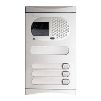
DOOR PANEL DESCRIPTION DOOR PANEL INSTALLATION oor panel description. mbedding box positioning. closing heads CE-6xx embedding boxes 1xxx 1850 2xxx 1650 1450 grille module 3xxx push buttons module The upper part of the door panel should be placed at 1,65m. height roughly. The hole dimensions will depend on the number of door panel modules. - Page 4 DOOR PANEL INSTALLATION DOOR PANEL INSTALLATION lace the embedding ssembly the sound module. box. Pass the wiring through the hole made in the bottom part of the embedding box. Level and flush the embedding box. Once the embedding box is placed, remove the protective labels from the attaching door panel holes.
- Page 5 DOOR PANEL INSTALLATION DOOR PANEL INSTALLATION old the door panel on the ableado de los embedding box. pulsadores. Select a direction to open the door panel; this selection should ease the door panel wiring. The opening direction will be settled through the hinges position, For a quality finish, pass the push buttons wires through that must be passed through the header clips as shown.
- Page 6 DOOR PANEL INSTALLATION DOOR PANEL INSTALLATION ush buttons wiring. ush buttons limit. The CN2 connector of the EL500 microprocessed circuit has The maximum number of push buttons to be connected depends on the number of installed 8 terminals (P1 to P8) for the connection of push buttons EL516 encoders, as it is shown on the following chart: or EL516 encoders.
- Page 7 DOOR PANEL INSTALLATION DOOR PANEL INSTALLATION Coming from previous page escription of the configuration escription of the configuration dip jumpers. switch. Set to ON the switch number 2 for monitor or telephones The JP1, JP2, JP3 and JP4 configuration jumpers programming.
-
Page 8: Lamps Wiring
DOOR PANEL INSTALLATION POWER SUPPLY INSTALLATION amps wiring. nstalling the FA-PLUS and FA-PLUS/C power supplies. The power supply must be installed in a dry and Once the nameplate labels are placed, wire the 3,5 x 25 protected place. It's recommended to protect lamps from different modules and connect them DIN-7971 the power supply by using a thermo-magnetic... -
Page 9: Platea Plus Monitor
MONITOR DESCRIPTION MONITOR DESCRIPTION escription of the Platea Plus unction push buttons. monitor. On-Off push button. After any monitor reset and during the next 45 seconds, all the monitor functions will be disabled, with the exception of call reception. 0000000000 Monitor Nº... -
Page 10: El562 Module
MONITOR ADJUSTMENTS MONITOR CONNECTOR DESCRIPTION L562 module for video escription of the RCPL-Plus inst a llations with twisted pair monitor connector. Locate the CN4 connector, that's placed in the monitor base. Remove the existing jumper and plug the EL562 module. NOTE: on this type of installations the EL560 module must be plugged in the EL500 microprocessed circuit (page 12). -
Page 11: Monitor Installation
MONITOR INSTALLATION MONITORS PROGRAMMING ix the monitor connector to the rogramming the wall. monitors. Avoid to place the monitor near to heating sources, Set to ON the switch number 2 of the configuration dip switch, that's in dusty locations or smoky environments. accessible by opening the terminal connector protection cover. -
Page 12: Description
TELEPHONE DESCRIPTION TELEPHONE DESCRIPTION escription of the T-940 Plus erminal connector description. telephone. – positive, ground. A , D : audio, digital communication. Telephone handset. INT : intercom. Speaker grille. SA : auxiliary calling device output. Microphone hole. HZ- : door bell push button input. -
Page 13: Programming
TELEPHONES PROGRAMMING INSTALLATION DIAGRAMS rogramming the onnexion of an a.c. lock release. telephones. As it is described on page 14, the lock releases to be connected to the door panel Set to ON the switch number 2 of the configuration dip switch, that's must be d.c. -
Page 14: Video Installation With Coaxial
INSTALLATION DIAGRAMS * Take off JP1 jumper of all the distributors except in the last one. D4L-PLUS ideo installation with coaxial cable. Malla Malla The installation diagram shows the connection of a video system with one or several door panels for the same building. If the system has one door panel only, override the wiring to the second door panel. -
Page 15: Video Installation Without Coaxial
INSTALLATION DIAGRAMS EL562 EL562 * Take off JP1 jumper of all the distributors except in the last one. ideo installation without coaxial D6L-Plus/2H cable. The installation diagram shows the connection of a video system with one or several door panels for the same building. If the system has one door panel only, override the wiring to the second door panel. -
Page 16: Audio Installation
INSTALLATION DIAGRAMS T-940 Plus T-940 Plus udio installation. The installation diagram shows the connection of an audio system with one or several door panels for the same building. If the system has one door panel only, override the wiring to the second door panel. If the system has more than one door panel, wire the second panel as shown on the diagram. -
Page 17: Optional Connections
OPTIONAL CONNECTIONS OPTIONAL CONNECTIONS xternal lock release ntercom function. activation. The lock release can be activated at any moment Platea Plus monitor and T-940 Plus telephone have intercom facility between two units of the by using an external push button, that must be same apartment . -
Page 18: Optional Connections
OPTIONAL CONNECTIONS TROUBLESHOOTING HINTS An easy way to check that the system is working properly is to disconnect the ctivation of a second wiring from the door panel and to check the monitor directly connected to the EL500 camera. circuit. No shortcircuit will damage the connected units, with the exception of a shortcircuit between CTO and ' ' monitor or distributor terminals.
Need help?
Do you have a question about the T500EN and is the answer not in the manual?
Questions and answers