Table of Contents
Advertisement
to register your set, or to order replacement parts please visit
SAVE THIS ASSEMBLY MANUAL FOR FUTURE REFERENCE IN THE EVENT THAT
Made in China | INS-2200081-A-BRIARCLIFF-ENG 08/02/21
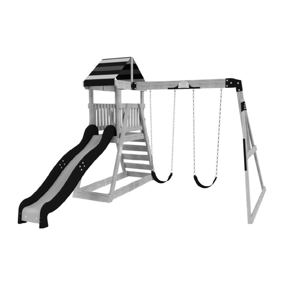
BRIARCLIFF
Model # 2200081
average 2 person assembly time
assembly time may vary based on skill level
For the most up to date assembly manual,
www.backyarddiscovery.com
YOU NEED TO ORDER REPLACEMENT PARTS.
Wooden Swing Set
Owner's Manual & Assembly Instructions
WARNING: FOR DOMESTIC USE ONLY.
MANUFACTURED BY:
Backyard Discovery
3305 Airport Drive
Pittsburg, KS 66762
800-856-4445
Advertisement
Table of Contents

Related Manuals for Backyard Discovery BRIARCLIFF


Summary of Contents for Backyard Discovery BRIARCLIFF
- Page 1 For the most up to date assembly manual, to register your set, or to order replacement parts please visit www.backyarddiscovery.com SAVE THIS ASSEMBLY MANUAL FOR FUTURE REFERENCE IN THE EVENT THAT YOU NEED TO ORDER REPLACEMENT PARTS. Made in China | INS-2200081-A-BRIARCLIFF-ENG 08/02/21...
- Page 2 INSTALLATION SERVICES AVAILABLE! Need a helping hand? Let our team of professionals handle the installation for you! *Installation services are only available to U.S. customers. With Go Configure, we bring you 18 years of experience right to your doorstep. We service a wide array of indoor and outdoor recreation products that most consumers don’t have the time or ability to deliver &...
- Page 3 Owner’s Manual Please Read This Before Starting Assembly MISSING A PART? CALL US BEFORE GOING BACK TO THE STORE Th e store where you made your purchase does not stock parts for this item. If you have assembly questions or you are missing or have damaged parts, please call 1-800-856-4445 you can also visit www.backyarddiscovery.com...
-
Page 4: Limited Warranty
All wood carries a five (5) year warranty against rot and decay from the original purchase date. Backyard Discovery Metal Play Structure Backyard Discovery warrants this metal play product to be free from defects in materials and workmanship for a period of five (5) years from the original date of purchase. General Warranty Information This warranty applies to the original owner and registrant and is non-transferable. -
Page 5: Burn Hazard
Owner’s Manual Operating Instructions and Safety Warnings WARNING: BURN HAZARD • Pay special attention to plastic and metal surfaces as they may be hot enough to cause burns. • Always check the temperature of the product before NOTE: letting your children play on it. •... - Page 6 Owner’s Manual Please Read This Before Starting Assembly Positioning Your Playcenter Suggested Playground Surfacing • Th e playcenter is designed to be installed on a level • Do not install home playground equipment over surface by an adult with an adult helper. Place concrete, asphalt, packed earth, grass, carpet, or any in a fl at area of your yard to minimize ground other hard surface.
- Page 7 Owner’s Manual Please Read This Before Starting Assembly APPENDIX A The following information is from the United States X3.1.3.2 Do not install loose-fi ll surfacing over hard surfaces such as concrete or asphalt. Consumer Product Safety Commission’s Information X3.1.4 Poured-In-Place Surfaces or Pre-Manufactured Sheet for playground surfacing material;...
- Page 8 • Check all moving parts including swing seats, Backyard Discovery assumes no responsibility or ropes, cables, and chains for wear, rust, or other liability for any charge incurred by the Customer for deterioration.
-
Page 9: Instructions For Proper Maintenance
About Our Wood Backyard Discovery uses 100% Cedar (C. Lanceolata) wood. Although we take great care in selecting the best quality lumber available, wood is still a product of nature and susceptible to weathering which can change the appearance of your set. - Page 10 Owner’s Manual Assembly Tips Protrusion Hazard Incorrect Correct If you see exposed threads and your bolt protrudes beyond the T-Nut you may have over tightened the bolt or used incorrect hardware. If you’ve overtightened, remove the bolt and add washers to eliminate the protrusion.
-
Page 11: Assembly Tips
Owner’s Manual Assembly Tips ASSEMBLY TIP: Keep an eye out for these boxes which will contain helpful pictures and information making the assembly process as quick and painless as possible. Sorting Wood When removing the wood from the boxes we recommend arranging them by part number before you begin assembly. - Page 12 Owner's Manual Tools Required for Installation...
- Page 13 Owner's Manual Basic Setup Dimensions & Assembly Notes Place the set on level ground, not less than 6'-7" [2 m] from any structure or obstruction such as a fence, garage, house, overhanging branches, laundry lines, or electrical wires. • While assembling unit, take time before and after each phase to make sure fort is level. If fort is not level, assembly will be difficult and improper assembly may result.
-
Page 14: Parts Identification
Parts Identification Owner's Manual Wood Components (Not to Scale) FLOOR SUPPORT - W4L15661 1 3/8"x3 3/8"x3 3/8" (36x86x86) (x4) UPRIGHT - W4L15680 1 3/8"x3 3/8"x40" (36x86x1016) (x2) UPRIGHT - W4L15687 (x2) 1 3/8"x3 3/8"x40" (36x86x1016) UPRIGHT - W4L15701 1 3/8"x3 3/8"x29" (36x86x737) (x4) UPRIGHT - W4L15699 1 3/8"x3 3/8"x43"... - Page 15 Parts Identification Owner's Manual Wood Components (Not to Scale) GROUND BOARD - W4L15697 1"x5 1/4"x36 7/8" (24x134x936) (x4) FLOOR JOIST - W4L15666 1"x3 3/8"x36 5/8" (24x86x930) (x1) FLOOR FRAME - W4L15667 1"x3 3/8"x23" (24x86x585) (x2) FLOOR FRAME - W4L15668 1"x3 3/8"x41 1/4" (24x86x1049) (x2) WALL RAIL - W4L15670 1"x3 3/8"x36 5/8"...
- Page 16 Parts Identification Owner's Manual Wood Components (Not to Scale) SAFETY BOARD - W4L15698 (x1) 5/8"x4 3/8"x27 3/4" (16x112x705) FLOOR BOARD - W4L15663 5/8"x3 3/8"x24 7/8" (16x86x633) (x7) FLOOR BOARD - W4L15664 5/8"x3 3/8"x24 7/8" (16x86x633) (x2) TOP RAIL - W4L15676 5/8"x3 3/8"x24 7/8"...
- Page 17 Parts Identification Owner's Manual Wood Components (Not to Scale) SB01 SWING BEAM 2 POSITION - W4L15691 2"x5 1/4"x36 3/4" (50x134x934) (x1) SB02 SWING BEAM 2 POSITION - W4L15692 2"x5 1/4"x41 1/8" (50x134x1043) (x1) FLOOR BOARD - W4L15665 5/8"x3 3/4"x20 1/8" (16x97x511) (x1) UPRIGHT - W2A03274 1 3/8"x3 3/8"x43"...
-
Page 18: Hardware Components
Owner's Manual Parts Identification Hardware Components H100115 BOLT WH H100165 BOLT WH (x11) 5/16x1/2 (x2) 5/16x5 1/4 H100008 BOLT WH H100005 NUT BARREL WH (x9) 5/16x1 (x14) 5/16x7/8 H100143 BOLT WH H100009 BOLT WH H100140 NUT BARREL WH (x4) 1/4x1-1/2 (x15) 5/16x1 1/4 (x4) - Page 19 Owner's Manual Parts Identification Hardware Components H100136 NUT BARREL WH (x7) 1/4x5/8 H100110 NUT LOCK H100030 WASHER LOCK EXT (x7) 5/16 (x84) 8x19 H100490 BOLT WH (x11) 1/4x5/8 H100141 BOLT WH H100139 WASHER LOCK EXT H100138 WASHER LOCK EXT (x2) 1/4 x 1/2"...
- Page 20 Owner's Manual Parts Identification Accessory Components (Not to Scale) A100178 AUGER GROUND STAKE (x6) A100069 QUICK LINK (x4) SWING SEAT A6P00133 (x2) BLUE 22" A4M01501 CHAIN BLUE 47" (x4) A100153 L BRACKET (x2) 66x66x127 BLUE A4M01110 90° L-BRACKET - BLK (x6) METAL A4M00938...
- Page 21 Owner's Manual Parts Identification Accessory Components (Not to Scale) A6P00496 TARP (x1) A6P00180 SLIDE BED LIME (x1) A6P00177 A6P00176 SLIDE RAIL BOTTOM LEFT SLIDE RAIL TOP LEFT (x1) (x1) A6P00179 A6P00178 SLIDE RAIL BOTTOM RIGHT SLIDE RAIL TOP RIGHT (x1) (x1) A100314 "A"...
- Page 22 SWING BEAM STEP 1 ASSEMBLY SB02 SWING BEAM 2 POSITION - W4L15692 SB01 SWING BEAM 2 POSITION - W4L15691 2"x5 1/4"x41 1/8" (50x134x1043) (x1) 2"x5 1/4"x36 3/4" (50x134x934) (x1) H100165 BOLT WH H100074 T-NUT (x2) 5/16x5 1/4 (x2) 5/16 SWING BEAM A4M01433 JOINT BRACKET H100140...
- Page 23 SWING BEAM STEP 2 ASSEMBLY A100153 L BRACKET (x2) 66x66x127 BLUE SWING BEAM SWING BEAM A4M00512 A4M00511 EXT BRACKET EXT. BRACKET (x1) (x1) BLUE - RIGHT BLUE - LEFT H100047 BOLT HEX H100110 NUT LOCK (x2) 5/16x2 3/4 H100011 BOLT WH H100005 (x2) NUT BARREL WH...
- Page 24 SWING BEAM STEP 3 ASSEMBLY H100099 SWING HANGER H100110 NUT LOCK (x4) 5/16x9 1/2 (x4) H100105 5/16 WASHER FLAT H100103 WASHER SAFETY (x4) 8x27 (x4) 17x30 (x4) NUT - 5/16" (x4) WASHER - 8x27 (x4) WASHER - 17x30 (x4) SWING HANGER - 9 1/2"...
- Page 25 SWING BEAM STEP 4 ASSEMBLY ANGLE BRACE - W4L15695 1 3/8"x3 3/8"x36 1/4" (36x86x921) (x2) H100074 T-NUT SWING BEAM SUPPORT - W4L15683 (x6) A-FRAME 5/16 A4M01174 2"x3 3/8"x44 1/4" (50x86x1123) (x1) (x1) BRACKET TIP: HAND TIGHTEN HARDWARE H100018 H100009 BOLT WH BOLT WH (x2) (x4)
- Page 26 SWING BEAM STEP 5 ASSEMBLY H100013 H100008 BOLT WH BOLT WH (x4) (x2) 5/16x1 5/16x2 1/4 ANGLE BRACE - W4L15694 1 3/8"x3 3/8"x38 1/4" (36x86x973) (x2) GROUND BOARD - W4L15696 H100030 WASHER LOCK EXT H100074 T-NUT (x6) (x2) 1"x3 3/8"x37 5/8" (24x86x955) 8x19 (x6) 5/16...
- Page 27 SWING BEAM STEP 6 ASSEMBLY METAL END SUPPORT - W4L15685 A4M00938 L-BRACKET - 1"x3 1/2"x39 1/2" (24x86x1000) (x1) (x2) BLUE NOTE: FULLY TIGHTEN HARDWARE NOW H100166 H100013 BOLT WH BOLT WH (x4) (x2) 5/16x4-1/4 5/16x2 1/4 H100009 H100074 BOLT WH T-NUT H100030 WASHER LOCK...
-
Page 28: A-Frame Assembly
SWING BEAM STEP 7 ASSEMBLY SWING BEAM ASSEMBLY (x1) H100011 BOLT WH H100005 NUT BARREL WH (x2) 5/16x1 3/4 (x2) 5/16x7/8 A-FRAME ASSEMBLY (x1) SWING BEAM ASSEMBLY (x1) (x2) NUT BARREL - 7/8" (x2) BOLT - 1 3/4" NOTE: FULLY TIGHTEN ALL HARDWARE NOW A-FRAME ASSEMBLY (x1) - Page 29 FORT ASSEMBLY STEP 1 WALL RAIL - W4L15670 H100013 BOLT WH 1"x3 3/8"x36 5/8" (24x86x930) (x1) (x6) 5/16x2 1/4 UPRIGHT - W4L15701 1 3/8"x3 3/8"x29" (36x86x737) (x2) WALL RAIL - W4L15671 (x1) 1"x3 3/8"x36 5/8" (24x86x930) H100074 H100030 T-NUT WASHER LOCK EXT (x6) (x10) 8x19...
- Page 30 STEP 2 FORT ASSEMBLY WALL RAIL - W4L15670 H100013 BOLT WH 1"x3 3/8"x36 5/8" (24x86x930) (x1) (x6) 5/16x2 1/4 UPRIGHT - W4L15701 1 3/8"x3 3/8"x29" (36x86x737) (x2) WALL RAIL - W4L15671 1"x3 3/8"x36 5/8" (24x86x930) (x1) H100074 T-NUT H100030 WASHER LOCK EXT (x10) 5/16 (x6)
- Page 31 STEP 3 FORT ASSEMBLY UPRIGHT - W4L15680 H100166 FLOOR FRAME - W4L15667 BOLT WH (x2) 1 3/8"x3 3/8"x40" (36x86x1016) 1"x3 3/8"x23" (24x86x585) (x8) (x2) 5/16x4-1/4 UPRIGHT - W4L15687 FLOOR FRAME - W4L15668 H100013 BOLT WH H100074 T-NUT (x2) 1 3/8"x3 3/8"x40" (36x86x1016) (x2) 1"x3 3/8"x41 1/4"...
- Page 32 STEP 4 FORT ASSEMBLY H100090 SCREW PFH FLOOR SUPPORT - W4L15661 (x12) 8x2 1/2" 1 3/8"x3 3/8"x3 3/8" (36x86x86) (x4) A100314 "A" REVISION TAG (x1) H100128 SCREW PWH (x2) FLOOR JOIST - W4L15666 8x5/8 (x1) 1"x3 3/8"x36 5/8" (24x86x930) NOTE HOLES UP ALL (E01) BOARDS (x8) SCREW - 2 1/2"...
- Page 33 STEP 5 FORT ASSEMBLY FLOOR BOARD - W4L15663 H100086 SCREW PFH FLOOR BOARD - W4L15665 5/8"x3 3/8"x24 7/8" (16x86x633) (x53) (x7) 8x1 1/2 (x1) 5/8"x3 3/4"x20 1/8" (16x97x511) H100111 SCREW PFH FLOOR BOARD - W4L15664 AJ01 ANGLE FLOOR BOARD - W4L15996 (x2) (x2) 5/8"x3 3/8"x24 7/8"...
- Page 34 STEP 6 FORT ASSEMBLY UPRIGHT - W4L15699 H100013 BOLT WH 1 3/8"x3 3/8"x43" (36x86x1091) (x1) H100030 (x16) WASHER LOCK EXT 5/16x2 1/4 (x18) 8x19 UPRIGHT - W2A03274 DECK ASSEMBLY H100008 BOLT WH (x1) 1 3/8"x3 3/8"x43" (37x86x1091) FROM STEP 5 H100074 T-NUT (x2)
- Page 35 STEP 7 FORT ASSEMBLY UPRIGHT - W4L15699 H100013 BOLT WH 1 3/8"x3 3/8"x43" (36x86x1091) (x1) H100030 (x16) WASHER LOCK EXT 5/16x2 1/4 (x18) 8x19 SIDE ASSEMBLY UPRIGHT - W4L15700 FROM STEP 1 H100008 BOLT WH 1 3/8"x3 3/8"x43" (36x86x1091) (x1) H100074 T-NUT (x2)
- Page 36 STEP 8 FORT ASSEMBLY SAFETY BOARD - W4L15698 H100063 H100108 WASHER LOCK H100072 BOLT PTH T-NUT GROUND BOARD - W4L15672 (x8) (x1) 5/8"x4 3/8"x27 3/4" (16x112x705) 1/4x3/4 (x8) (x8) (x2) 5/8"x5 1/4"x27 3/4" (16x134x705) 8x15 H100086 SCREW PFH ROCKWALL BOARD - W4L15673 BLUE HC ROCK (x28) A6P00041...
- Page 37 STEP 9 FORT ASSEMBLY PICKET - W4L15679 H100087 SCREW PFH (x56) 5/8"x2 3/8"x18 5/8" (16x60x472) 8x1 1/4 (x14) TIP: A HELPER IS RECOMMENDED TO CAREFULLY STAND PLAY-SET UP. (x14) (x56) SCREW - 1-1/4" INSTALL HARDWARE IN PILOT HOLES...
- Page 38 STEP 1 0 FORT ASSEMBLY H100013 BOLT WH TOP RAIL - W4L15675 H100030 (x8) WASHER LOCK EXT 5/16x2 1/4 (x1) 1"x5 1/4"x45 1/4" (24x134x1150) (x8) 8x19 H100074 T-NUT TOP RAIL - W4L15678 (x8) 1"x5 1/4"x45 1/4" (24x134x1150) 5/16 (x1) (x1) NOTE HOLE LOCATIONS (x1)
- Page 39 STEP 1 1 FORT ASSEMBLY H100490 BOLT WH H100136 NUT BARREL WH (x8) 1/4x5/8 (x4) 1/4x5/8 TOP RAIL - W4L15676 A4M01110 5/8"x3 3/8"x24 7/8" (16x86x633) (x2) 90° L-BRACKET - BLK (x4) H100072 T-NUT H100139 WASHER LOCK EXT (x4) (x4) 8x15 (x4) 90°...
- Page 40 STEP 1 2 FORT ASSEMBLY H100490 H100136 NUT BARREL WH BOLT WH H100141 TOP RAIL - W4L15677 BOLT WH (x2) (x2) 1/4x5/8 1/4x5/8 (x2) (x2) 5/8"x2 3/8"x21 1/8" (16x60x538) 1/4 x 1/2" A4M01110 90° L-BRACKET - BLK (x2) TOP RAIL - W4L15681 H100072 T-NUT H100139...
- Page 41 STEP 13 FORT ASSEMBLY H100128 SCREW PWH (x6) 8x5/8 A6P00496 TARP (x1) (x1) TARP 1 13/16 in [46mm] (x6) SCREW - 5/8...
- Page 42 STEP 14 FORT ASSEMBLY H100042 H100095 BOLT HEX WASHER SPLIT (x4) (x4) 5/16x1 1/4 5/16 SWING BEAM ASSEMBLY H100074 T-NUT H100105 WASHER FLAT (x4) 5/16 (x4) 8x27 (x4) T-NUT - 5/16" (x4) WASHER - 8x27 (x4) WASHER - 5/16" (x4) BOLT HEX - 1 1/4"...
- Page 43 STEP 15 FORT ASSEMBLY H100145 LAG SCREW WH H100138 WASHER LOCK EXT (x4) 1/4x1 1/2 (x4) 6x15 A6P00314 HAND GRIP BLUE PLASTIC (x2) (x4) WASHER - 6x15 (x4) LAG SCREW - 1 1/2" (x2) HAND GRIP...
-
Page 44: Quick Link
FORT ASSEMBLY STEP 16 A4M01501 CHAIN BLUE 47" (x4) A100069 QUICK LINK A6P00133 SWING SEAT (x4) (x2) BLUE 22" (x4) CHAIN BLUE 47" (x4) QUICK LINK (x2) SWING SEAT BLUE 22"... -
Page 45: Slide Assembly
SLIDE ASSEMBLY STEP 1 SLIDE BRACE - W4L15702 5/8"x3 3/8"x14 1/4" (16x86x362) (x1) A6P00180 SLIDE BED LIME (x1) H100074 T-NUT H100115 BOLT WH (x2) 5/16 (x2) 5/16x1/2 NOTE: TAKE NOTE OF SLIDE BED SURFACE FINISH, THE DULL SIDE WILL BE TOWARDS THE GROUND. PLACE SLIDE BRACE CENTERED ON THE BOTTOM (DULL SIDE) AND 1/2"... - Page 46 SLIDE ASSEMBLY STEP 2 A6P00176 A6P00177 SLIDE RAIL TOP LEFT SLIDE RAIL BOTTOM LEFT (x1) (x1) A6P00178 A6P00179 SLIDE RAIL TOP RIGHT SLIDE RAIL BOTTOM RIGHT (x1) (x1) H100005 NUT BARREL WH H100115 BOLT WH (x8) 5/16x7/8 (x8) 5/16x1/2 NOTE: REPEAT ON OTHER SIDE, MAKING A LEFT AND RIGHT ASSEMBLY.
- Page 47 SLIDE ASSEMBLY STEP 3 CENTER SLIDE BRACE - W4L15703 5/8"x3 3/8"x14 1/4" (16x86x362) (x2) NOTE: PLACE (1) SLIDE RAIL ASSEMBLY ON A FLAT SURFACE AND BEGIN INSERTING SLIDE BED AT THE BOTTOM OF THE SLIDE RAIL (FIGURE 1). HAVE A HELPER BEND THE SLIDE BED TOWARDS THE TOP OF THE SLIDE AND INSERT THE BED INTO THE SLIDE CAVITY.
- Page 48 SLIDE ASSEMBLY STEP 4 NOTE: PLACE SECOND SLIDE RAIL ASSEMBLY OVER THE TOP OF THE SLIDE BED AND M78 CENTER SLIDE BRACES. INSERT THE SLIDE BED AND CENTER SLIDE BRACES INTO THE SLIDE CAVITY. MAKE SURE SLIDE BED IS COMPLETELY IN THE SLIDE CAVITY. FAILURE TO INSERT SLIDE BED COMPLETELY AND SECURED MAY RESULT IN INJURY OR AMPUTATION.
- Page 49 SLIDE ASSEMBLY STEP 5 H100090 SCREW PFH (x24) 8x2 1/2" NOTE: USING AN 1/8" DRILL BIT, DRILL PILOT HOLES IN EACH INDENTATION ALONG EACH SIDE RAIL. THERE SHOULD BE 12 INDENTATIONS ON EACH RAIL. BE SURE TO DRILL THROUGH THE SLIDE RAIL AND THE SLIDE BED. THEN SECURE WITH THE PROVIDED HARDWARE.
- Page 50 FORT ASSEMBLY STEP 17 H100008 BOLT WH (x2) 5/16x1 SLIDE ASSEMBLY H100074 T-NUT (x2) 5/16 2 5/8 in [67 mm] 3 15/16 in 7 1/16 in 4 3/16 in [99 mm] [180 mm] [106 mm] 2 7/16 in [62 mm] 2 3/16 in CENTER SLIDE IN OPENING.
- Page 51 FORT ASSEMBLY STEP 18 H100009 BOLT WH H100074 A100178 T-NUT AUGER GROUND STAKE (x6) 5/16x1 1/4 (x6) 5/16 (x6) TWIST GROUND STAKES INTO GROUND IN LOCATIONS SHOWN. USING GROUND STAKE AS A GUIDE, DRILL 7/16" (10mm) HOLES FOR HARDWARE. (x4) BOLT - 1 1/4"...
Need help?
Do you have a question about the BRIARCLIFF and is the answer not in the manual?
Questions and answers