Advertisement
Quick Links
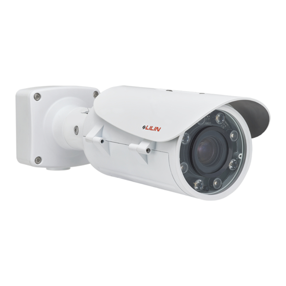
D/N HD AF IR IP CAMERA
Installation Guide
P
art Description & Dimensions
Top Case
1
Bottom Case
2
4
Lens
3
Sun Shield
4
Bottom Box
5
Top Box
6
2
Side Hole
7
182mm
Bottom Hole
8
Hole Plug
9
Adjustment Screw A
10
Adjustment Screw B
11
Adjustment Screw C
12
13
Factory default button
Restores the server back to factory default settings.
Micro SD card slot
14
15
Auto Focus button
16
Live Video Output Connector
17
LED Indicators
Green (Power): Indicates system status.
Green (Link): Illuminates when the camera is connected to a network
Orange (ACT): Flashes when data communication is in process.
The IP camera will automatically adjusts the camera lens to obtain focus after
press the AF (Auto Focus) button continuously for 2 seconds. User can adjust
the image view by using zoom in/out button via web access, and refocus using
the Auto-Focus link on the main Web page.
I
nstallation
1. Retrieve the camera and remove the bottom box from the top box with a hex
key (FIG.1), and remove the safety cable on the bottom box (FIG.2). Use the
included screws (M4.0x25) through the holes marked as "a", and fix the
camera in the desired location(FIG.3&4).
FIG.1
FIG.2
a
a
a
a
FIG.3
FIG.4
2. Firstly, insert the network cable and power cable through a pipe with ½" PT,
and then secure the pipe to the side hole or bottom hole (FIG.5. please make
sure the connection between the pipe and the side hole is watertight, and the
side hole is facing downwards).
To prevent the camera from falling, you should secure the safety cable(FIG.6).
372mm
6
5
1
112mm
10
11
12
7
333mm
84mm
13
14
17
16
15
FIG.5
FIG.6
3. Connect the network cable and power cable to the camera's RJ-45 connector
and power input, respectively (FIG.7). Secure the top box to the bottom box
(FIG.8).
+12V IN
GND
–
N.O.
DC12V
GND
—
COM.
N.O.
COM.
DIN
GND
DIN
AIN
GND
AOUT
GND
AIN
GND
AOUT
—485
+485
–485
+485
FIG.7
FIG.8
4. Adjust the three adjustment screws to move the camera to the desired angle,
and then tighten the adjustment screws (FIG.9~12).
FIG.9
FIG.10
FIG.11
66-8022CSB-1B
Change the Outlet Position for the Network Cable and Power Cable
1. Loosen the hole plug on the bottom box and secure it to the side hole (FIG.13).
2.Insert the network cable and power cable through bottom hole on the bottom
116mm
box (FIG.14), and then connect the network cable and power cable to the
camera's RJ-45 connector and power input, respectively (FIG.7). For
watertight installation, please refer to Installation-2.
3
FIG.13
ø95
S
ystem Architectures
For connecting IP Camera series to the network, please follow one of the
system architectures:
(1). Use DC12V power adaptor and network switch connected to a network.
8
LAN
84mm
Non-PoE Switch
IP CAMERA
DC12V Adaptor
9
(2). Use with PoE of the network switch connected to the network.
LAN
IP CAMERA
PoE Switch
(3). Use PoE power injector and the network switch connected to the network.
LAN
IP CAMERA
PoE Power Injector
E
mergency Factory Default
To restore the hardware to factory default settings, please follow these steps:
1.Press and hold "RESET Key" for 10 seconds and release.
2.Wait for about 40 seconds, and the network LED light should turn off, and
go back on again.
3.The camera is now restored to factory default settings, and will reboot
automatically.
4.Search for the IP device using the IPScan software.
5.Start the IP device via an Internet browser.
6.Enter the username and password to operate.
NOTE1:
The factory default username and password are empty, and the
user can set an account for login.
NOTE2:
The IP address will revert to the default setting of 192.168.0.200.
B
efore Accessing IP Cameras
Before accessing the IP camera, make sure that the camera's RJ-45
network, audio, and power cables are properly connected. To set the IP
address, consult your network administrator for an available IP address.
The default IP address for each IP camera is 192.168.0.200. Users can use
the default IP address for verifying the camera's network connection.
FIG.12
C
onfiguring IP Addresses via Web Interface
To change an IP address via web interface, type the default IP address
(192.168.0.200) in the Internet browser and follow the steps below:
1. Login to the Full HD IP camera with the set username and password.
2. Click Basic Mode configuration hyperlink.
3. Click Network->General hyperlink.
4. Change the IP address, subnet mask, gateway, or HTTP port for the IP
camera.
5. Click Submit to verify the settings.
S
oftware Requirements
Universal ActiveX software components are required for web interface
display of JPEG or Full HD video. When you login to the IP camera by
Internet Explorer, the security warning dialog box will prompt the
FIG.14
installation of the Universal ActiveX. Click Install to download it.
C
onfiguring IP Addresses with IPScan Software
To change the settings of the IP address, subnet mask, gateway, or HTTP
port, you can follow the steps below:
1. Run the IPScan software.
2. Click Refresh. All available devices should be listed in the device list.
3. Select your device from the list provided.
LAN / Internet
4. Change the IP address, subnet mask, gateway, or HTTP port for the IP
camera.
5. Click Apply to submit the settings.
6. Click Refresh to verify the settings.
PC
LAN / Internet
PC
LAN
LAN / Internet
AC
Non-PoE Switch
PC
L
ogin
The factory default username and password are empty. To login to the Full
HD IP camera, please set the username and password on the login page.
Press [Login] to complete the setting and login simultaneously.
IPCAM
Password have to meet the following
criteria:
1. More than or equal to 8 characters.
2. Allow uppercase letter, lowercase letter,
number digit, and special character.
3. Must have at least three types of
character sets.
Advertisement

Related Manuals for Lilin Z2R8022EX25


Summary of Contents for Lilin Z2R8022EX25
- Page 1 efore Accessing IP Cameras Before accessing the IP camera, make sure that the camera's RJ-45 network, audio, and power cables are properly connected. To set the IP D/N HD AF IR IP CAMERA address, consult your network administrator for an available IP address. The default IP address for each IP camera is 192.168.0.200.
- Page 2 軟 體需求 日夜兩用高畫質自動變焦紅外線 Full HD 網路攝影機需要軟體解壓縮器顯示影像,Full HD 網路攝影 機的網頁介面需使用該軟體。 當您第一次登錄本產品,Full HD 警語: 此圖示,指在廢棄產品時不可直接丟棄垃 網路攝影機 網路攝影機的網頁介面會自動安裝Universal ActiveX元件,請按下 圾桶,應進行拆解,並分類進行回收再利用。 「安裝」鍵安裝該元件。 圖 11 圖 12 安裝說明 使 用 頁面來設定 位址 HTML 變更網路電纜線和電源線的出線位置 部 件說明及尺寸 請先在網路瀏覽器網址列,輸入預設IP位址192.168.0.200。並按 1. 轉鬆取下接線盒底座的孔塞,再將其鎖緊在側孔上,( 圖13)。 照下列步驟執行,使用HTML頁面來更改IP位址: 2. 把網路電纜線和電源線穿過接線盒底座的底孔(圖14),然後將 372mm 116mm 1.
Need help?
Do you have a question about the Z2R8022EX25 and is the answer not in the manual?
Questions and answers