Advertisement
Quick Links
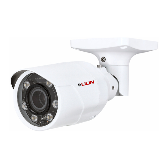
D/N HD (AF) IR IP CAMERA
Part Description & Dimensions
[HD AF IR IP Camera]
257.8
1
3
2
5
135
239.8
102.5
102.5
78
6
84
1
Camera Body
2
Window
3
Adjustment Screw A
Adjustment Screw B
4
5
Adjustment Screw C
6
Lens
7
LED Indicators
Green (Power): indicates system status.
Green (LINK): Illuminates when the camera is connected to a network.
Orange (ACT): Flashes when data communication is in process.
The IP camera will automatically adjusts the camera lens to obtain focus after pressing the AF
(Auto Focus) button continuously for 2 seconds. User can adjust the image view by using zoom
in/out button via web access, and refocus using the Auto-Focus link on the main Web page.
Installation
1. Remove the camera from the Box. Connect the Ethernet cable, video cable, and power cable to
the camera's RJ-45 network connector, video output connector respectively, and DC power-in
connector (FIG.1). Secure the camera to the wall (FIG.2).
Video output wire
DC Power Input
Network Cable
FIG.1
DC12V +
DC12V
DC12V -
Audio OUT
GND
AUDIO
Audio IN
GND
Alarm IN
ALARM
COM
Alarm OUT
Connect the RJ-45 Ethernet cable with a waterproof connector
First, remove the waterproof connector and unscrew the waterproof nut. Insert the Ethernet
cable and connect to the RJ-45 connector with proper tools (FIG.3). Then, tighten the
waterproof connector and nut before the RJ-45 connector is connected to the camera (FIG.4).
FIG.3
2. Loosen the three adjustment screws on the bracket to change the camera direction according
to different needs before according to different needs.
Be sure to tighten the screws after the adjustment is completed (FIG.5–10).
FIG.5
Installation Guide
[HD IR IP Camera]
227.8
1
2
5
4
105
209.8
7
8
8
Live Video Output
9
Reset Key
Restores the camera back to factory default settings.
Micro SD Card Slot
10
11
AF Key [Auto Focus Model Only]
FIG.2
FIG.4
FIG.6
66-8122OOE-1
3
FIG.7
4
FIG.9
9
Install the Camera with a Junction Box (Optional)
10
A. Choose a desired position for the junction box, and secure the truss head screws enclosed
in the box to the holes marked as "a" (FIG.11 & 12) on the junction box.
11
Unit: mm
FIG.11
B. Insert the Ethernet cable, video cable, and power cable through the 1/2"PT tube (FIG.13),
and rotate to secure the tube to the holes on the lateral or bottom of the junction box
(FIG.14). The conjuction between the tube and the hole must be airtight, and the opening
of the hole must point downward.
FIG.13
C. Attach the safety cable to the hole at the bottom of the junction box (FIG.15), and connect
the Ethernet cable, video cable, and power cable to the camera's RJ-45 connector, video
output, and power input respectively (FIG.16). Please refer to "1." For more wiring
instructions.
FIG.15
C. Use the screws (M5.0x12L) included in the box to secure the camera to the junction box,
and tighten the screws (FIG.17&18).
FIG.17
Change the Outlet Position for the Ethernet and Power Cables
1.
Loosen the threaded plug at the bottom of the junction box and secure it to the lateral
hole (FIG.19).
2. Insert the Ethernet cable, video cable, and power cable through the opening at the
bottom of the junction box (FIG.20) and connect them to the camera's RJ-45 connector,
video output, and power input respectively (refer to "1" for more instructions on wiring).
FIG.19
FIG.8
FIG.10
a
a
a
a
FIG.12
FIG.14
Video output wire
DC Power Input
Network Cable
FIG.16
FIG.18
FIG.20
Advertisement

Related Manuals for Lilin Z2R8122X-P


Summary of Contents for Lilin Z2R8122X-P
- Page 1 D/N HD (AF) IR IP CAMERA Installation Guide 66-8122OOE-1 Part Description & Dimensions [HD AF IR IP Camera] [HD IR IP Camera] 257.8 227.8 FIG.7 FIG.8 209.8 239.8 102.5 FIG.9 FIG.10 102.5 Install the Camera with a Junction Box (Optional) A.
- Page 2 4. Change the IP address, subnet mask, gateway, or HTTP port for the IP camera. System Architectures 5. Click Apply to submit the settings. For connecting D/N 1080P HD IP Camera series to the network, please follow one 6. Click Refresh to verify the settings. of the system architectures: (1).
Need help?
Do you have a question about the Z2R8122X-P and is the answer not in the manual?
Questions and answers