Table of Contents
Advertisement
Quick Links
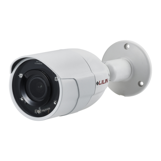
D/N HD AF IR IP CAMERA
Part Description & Dimensions
1
69
4
74
φ58
5
φ70
φ58
3
3-120°
1
Front Cover
Main Body
2
Bracket Base
3
Window
4
Installation
1. Remove the camera from the box first. Connect the Ethernet cable and power
cable to the camera's RJ-45 network connector and DC power-in connector
(FIG.1).
Secure the camera to the wall (FIG.2).
NETWORK CABLE
DC POWER INPUT
Audio OUT
FIG. 1
GND
AUDIO
Audio IN
GND
Alarm IN
ALARM
COM
Alarm OUT
Connect the RJ-45 Ethernet cable with a waterproof connector
First, remove the waterproof connector and unscrew the waterproof nut.
Insert the Ethernet cable and connect to the RJ-45 connector with proper
tools (FIG.3). Then, tighten the waterproof connector and nut before the
RJ-45 connector is connected to the camera (FIG.4).
Instruction Manual
189
2
3
77
176
6
Lens
5
Micro SD card slot
6
Factory default button
7
66-8822AOOE-1B
FIG.3
2. Adjust the five adjustment screws to move the camera to the desired angle,
and then tighten the adjustment screws (FIG.5~10).
7
Unit: mm
Inserting a Micro SD Card
First remove the screw under the front cover, then rotate the front cover
counterclockwise to remove it and insert a Micro SD card (FIG.11 & 12).
System Architectures
For connecting D/N HD IP Camera series to the network, please follow one of the
FIG. 2
system architectures:
(1). Use DC12V power adaptor and network switch connected to a network.
HD IP CAMERA
FIG.4
FIG. 5
FIG. 7
FIG. 9
FIG. 11
LAN
LAN / Internet
Non-PoE Switch
PC
DC12V Adaptor
FIG. 6
FIG. 8
FIG. 10
FIG. 12
Advertisement
Table of Contents

Subscribe to Our Youtube Channel
Summary of Contents for Lilin Z2R8852AX
- Page 1 D/N HD AF IR IP CAMERA Instruction Manual 66-8822AOOE-1B Part Description & Dimensions FIG.3 FIG.4 2. Adjust the five adjustment screws to move the camera to the desired angle, and then tighten the adjustment screws (FIG.5~10). FIG. 5 FIG. 6 φ58 φ70 FIG.
- Page 2 (2). Use with PoE of the network switch connected to the network. LAN / Internet PoE Switch HD IP CAMERA (3). Use PoE power injector and the network switch connected to the network. LAN / Internet Non-PoE Switch HD IP CAMERA PoE Power Injector Emergency Factory Default Configuring IP Addresses via Web Interface...


Need help?
Do you have a question about the Z2R8852AX and is the answer not in the manual?
Questions and answers