Advertisement
Quick Links
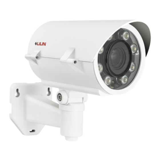
D/N HD AF VF IR IP CAMERA
Part Description & Dimensions
109
105
70
80
13
Unit: mm
Installation
1. First, remove the bracket from the box. Insert the DC12V power cable and network cable
through the bracket and secure it to the wall (FIG.1 & FIG.2).
2. Remove the camera body from the box and open the top cover with screw driver
(FIG.3).
3. Insert the DC12V power cable and network cable through the rubber cover and then
pull the cables through the bottom of camera body (FIG.4). Connect the DC12V power
cable to the DC power terminal and connect the network cable to RJ-45 connector of
the IP camera (FIG.5).
4. Use the provided M5.0x10 screws (2x silver) to secure the camera body to the
bracket with a screw driver (FIG.6).
Instruction Manual
231
200
90
160
SUN SHIELD
TOP COVER
BOTTOM CHASSIS
BRACKET
PAN ADJUSTMENT SCREW
TILT ADJUSTMENT SCREW
WINDOW
FIG. 1
FIG. 3
FIG. 4
66-7422CSE-1B
5. Loosen the pan and tilt adjustment screw on the bracket to turn the camera body
to the desired angle and then tighten the screw (FIG.7).
6. Replace the top cover and tighten the screws with a screw driver (FIG.8&
FIG.9).
System Overview
Top View & Input/Output Device Component Description
SD Card
Connector
DC12V Power
Input Connector
Load Default Button
Auto Focus Button
FIG. 2
System Architectures
For connecting HD IP Camera series to the network, please follow one of the system
architectures:
(1). Use DC12V power adaptor and network switch connected to a network.
HD IP CAMERA
(2). Use with PoE of the network switch connected to the network.
LAN
HD IP CAMERA
(3). Use PoE power injector and the network switch connected to the network.
FIG. 5
LAN
HD IP CAMERA
F I G . 6
F I G . 7
F I G . 8
LAN
LAN / Internet
Non-PoE Switch
DC12V Adaptor
LAN / Internet
PoE Switch
PC
LAN
LAN / Internet
AC
Non-PoE Switch
PoE Power Injector
F I G . 9
Alarm/Audio
In/Out Connector
RJ-45 Jack
Video Out Jack
PC
PC
Advertisement

Summary of Contents for Lilin ZMR7442X-P
- Page 1 D/N HD AF VF IR IP CAMERA 66-7422CSE-1B Instruction Manual Part Description & Dimensions F I G . 6 5. Loosen the pan and tilt adjustment screw on the bracket to turn the camera body to the desired angle and then tighten the screw (FIG.7). F I G .
- Page 2 Emergency Factory Default Configuring IP Addresses via Web Interface To restore the hardware to factory default settings, please follow these steps: To change an IP address via web interface, type the default IP address 1.Press and hold “RESET Key” for 10 seconds and release. (192.168.0.200) in the Internet browser and follow the steps below: 2.Wait for about 40 seconds, and the network LED light should turn off, and go back on again.


Need help?
Do you have a question about the ZMR7442X-P and is the answer not in the manual?
Questions and answers