
Subscribe to Our Youtube Channel
Related Manuals for NeoDen NeoDen9


Summary of Contents for NeoDen NeoDen9
- Page 1 NeoDen9 High Speed Pick and Place Machine User Manual Model: Neoden9 High Speed Pick and Place Machine Version: V1.0 Zhejiang Neoden Technology Co., Ltd...
- Page 2 Figure A:the trapezoid screw on the track’s left and right; Figure B:the line rails of moving load-carrying on the y-axis’s left and rightY; Figure C:the line rails of moving load-carrying on the track’s left and right; Figure C Figure B Zhejiang Neoden Technology Co., Ltd...
-
Page 3: Table Of Contents
1. Equipment installation and precautions............................4 1.1 Machine Dimension................................4 1.2 Structure of Neoden9..............................5 1.3 Working Area Structure..............................6 1.4 Important Notice................................8 1.5 Operation flow chart............................... 9 1.6 Flow chart of making a programming file........................10 2.PCB Editing..................................... 11 2.1 PCB information................................12 2.1.2 Backward................................... -
Page 4: Equipment Installation And Precautions
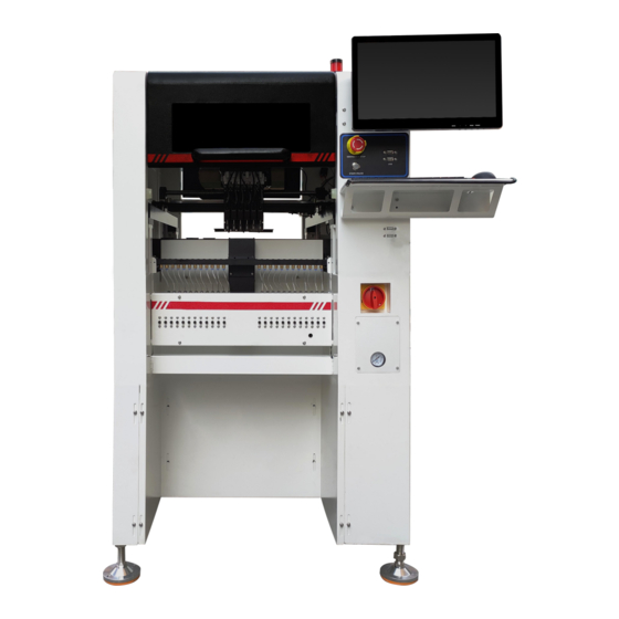
1. Equipment installation and precautions 1.1 Machine Dimension Figure 1- Machine dimension Zhejiang Neoden Technology Co., Ltd... -
Page 5: Structure Of Neoden9
1.2 Structure of Neoden9 (1) (5) (6) (2) (7) (8) (9) (3) (10) (4) (11) (12) Figure 2-Ports and Appearance (1)Warning Light(Triple Color) (7) USB port (2)Safety cover (8)Pause button (3)Front Feeder Slots 1-33(Reference value representation) (4)Electric Feeder Port (9)Mouse keyboard bracket (10)Power Switch... -
Page 6: Working Area Structure
1.3 Working Area Structure Figure 3- Top view of main mounting area Zhejiang Neoden Technology Co., Ltd... - Page 7 Figure4- X-axis Beam Figure5- Main Placement Head Camera Zhejiang Neoden Technology Co., Ltd...
-
Page 8: Important Notice
Figure 6-The air supply of the equipment shall not be less than0.55MP Figure 7- Feeder Pressure 0.5MP Remark: At 0.55MPA pressure input, the air consumption of the machine is 12L/min. It is recommended to use a compressed airtank of no less than 70L. Zhejiang Neoden Technology Co., Ltd... -
Page 9: Operation Flow Chart
Power OFF Shut down the system via computer, then power off the machine. Disconnect the electricity supply after the system being powered off. Keep the machine clean, daily maintenance of the nozzles assures high utility. Zhejiang Neoden Technology Co., Ltd... -
Page 10: Flow Chart Of Making A Programming File
A. The basic procedure of making a programming file by manual programming or import coordinate file is similar, but there are two different parts: component list and fiducial setting. B. Please find the detailed operation steps of the differences on relative page. Zhejiang Neoden Technology Co., Ltd... -
Page 11: Pcb Editing
(8) Add a new file: click Add to open the input window, input the file name, and click OK. At this time, when the file Zhejiang Neoden Technology Co., Ltd... -
Page 12: Pcb Information
Click “Backward”, cylinder will descend and pcb be transit to the end of track, it will stop above the sensor position. If there’s SMT conveyor connected and release signal to pnp machine, pcb will be automatically transit into SMT conveyor. Zhejiang Neoden Technology Co., Ltd... -
Page 13: Panelized Board Information
Click “single board setting”, you will see the “align” button of the SMD1 position that means the first component on the component setup. Click “align” to enter the vision align interface, we need find the first component that on the component list, generally we choose the center of the component, see figure: Zhejiang Neoden Technology Co., Ltd... - Page 14 PCB angle automatically. When you program under the mode of import coordinate file, no need to set this step. The default angle under this mode will be 0°. Zhejiang Neoden Technology Co., Ltd...
- Page 15 “PCB information” automatically. After setup, click “create panelized list”, the panelized list will be generated accordingly in the blank. You can also double- confirm each position by clicking “Align”. Zhejiang Neoden Technology Co., Ltd...
- Page 16 The data of “right top”on original board: on the alignment interface, find the right top panel that is nearest to the right side but nearest to the feeding position, then find the first component which on the chip list of this panel, align the Zhejiang Neoden Technology Co., Ltd...
-
Page 17: Coordinate Information
1.PCB Mark Point (1)Panelized mark point It is mainly used for multiple identical PCB boards consistent of the whole board, when place every panel board, the machine will rescan small panel board’s mark point. (2)Single mark point Zhejiang Neoden Technology Co., Ltd... -
Page 18: Mark Point Alignment
"Mark align" see below figure, and then click "Save and Back" to go back to main page. (2)Min, max value Zhejiang Neoden Technology Co., Ltd... -
Page 19: Component List Setting
4.2 Component list setting Function: display the information and mounting order of components. The components’ quantity and mounting information can be added through manual programming or importing files , see below figure: Zhejiang Neoden Technology Co., Ltd... - Page 20 It can be set through feeder setting interface with ‘Assign all sequentially’ button to assign the infor mation to component list automatically. 2.Import the processing file (1)Export the component coordinate information through computer by choosing metric system CSV format to the USB flash disk. Zhejiang Neoden Technology Co., Ltd...
- Page 21 Move to head position: To move the selected component to the first row. Please notice the first row component must be the same as the first component to place on the PCB. (4)Convert to current machine coordinate Zhejiang Neoden Technology Co., Ltd...
- Page 22 It will fix it automatically at the second placement. (6)Batch create components Some circuit boards are relatively regular and easy in real editing situation. For this type of circuit board, we can generate coordinate in batch , the interface as shown in figure: Zhejiang Neoden Technology Co., Ltd...
- Page 23 Choose circle panel, the component number is 24 in the example, the angle is 0. Since the quantity of component is even number, we only need to find two symmetry components to align, Start point and Component point 2. After that, click create, the 24 components coordinate will be generate automatically. Zhejiang Neoden Technology Co., Ltd...
- Page 24 Component point 2 Component Start point 3 point All components’ setting on this files list, such as nozzle selecting, stack setting, the coordinates of pick components, adjustment setting, and others components’ setting need to be fulfilled here. Zhejiang Neoden Technology Co., Ltd...
- Page 25 After click to save,the coordinate information will be finished. Zhejiang Neoden Technology Co., Ltd...
-
Page 26: Feeder Information Setup
(2)Assign feeder and nozzle: After complete stack information and nozzle setting, click ‘Assign feeder and nozzle’, all information will update to the component list automatically (3)Batch editing for pick position: Press this button, it will show below: Zhejiang Neoden Technology Co., Ltd... -
Page 27: Feeder Setting
Start X, Start Y: It refers to the first IC in X/Y direction if the tray is in full package; If some ICs have been used whic h cause the tray is not full, you can directly set the exact position as actual situation, start X will be the location of its a Zhejiang Neoden Technology Co., Ltd... - Page 28 Zhejiang Neoden Technology Co., Ltd...
- Page 29 Notice: for edge position feeders, you can just use limited nozzle head to pick up components. If you’re not sure, just click “Feeder Test” button under the nozzle selection part. It will pop out below, you can test Zhejiang Neoden Technology Co., Ltd...
- Page 30 If the photo is with problem, you need to do some adjustment for the problematic recognition after finding the reason(such as interference reason and recognition Zhejiang Neoden Technology Co., Ltd...
-
Page 31: Nozzle Information
Below records the nozzle type of nozzle No.1-No.6. When replacing the nozzle, just replace the nozzle according to the file recorded nozzle type. 7. Assembly Interface Choose the programmed file in file listed interface, click “Mount”, it will go into assembly interface as below: Zhejiang Neoden Technology Co., Ltd... - Page 32 After analyzing the reason, you do not need to exit the assembly interface and just click “file edit” to modify it. After the modifying is finished, save it and come back to assembly interface. Config: press this button, a detailed configuration setting interface will pop out as below: Zhejiang Neoden Technology Co., Ltd...
- Page 33 (It is recommended for component whose size is bigger than that of 0603). For NeoDen9, the simultaneous pick nozzles are nozzle 1 and nozzle 4,or nozzle 2 and nozzle 5, or nozzle 3 and nozzle 6.
-
Page 34: Manual Test
Select the corresponding nozzle and click the up button and down button on the keyboard to to adjust the height of nozzle to make sure that the nozzle just presses on the upper plane of the track after the nozzle is lowered. After Zhejiang Neoden Technology Co., Ltd... - Page 35 Point 1, Point 2, Mid-point:This operation is used to select the center position of some components. For example, select " left mark camera" as alignment mode. First select the center of the first pin of the lower left foot Zhejiang Neoden Technology Co., Ltd...
-
Page 36: System Setup
Right buttons functions: Config save: to click Save after changing the parameter. Administrator login: to prevent any misoperation, this interface will be inactive and greys out. To make it inactive, Administrator needs to login. Zhejiang Neoden Technology Co., Ltd... -
Page 37: Feeder Position Config
The left column refers to feeder No., Pick X and Pick Y refer to the coordinates of pick offset. After “click to align”, this interface will be displayed. Align the center of component (edge of tablet), then save it. Zhejiang Neoden Technology Co., Ltd... -
Page 38: Component Positions Setup
9.2 Component Positions Setup Zhejiang Neoden Technology Co., Ltd... - Page 39 Save:After the marking operation is completed and the center position of the marking point is also selected, click save to save the data. Brightness:The brightness of the mark camera when recognizing an image, it can be adjusted in the drop-down list Zhejiang Neoden Technology Co., Ltd...
- Page 40 After the action is completed, click return, and the automatically measured data will be synchronized to the initial angle of the front IC camera in the right basic configuration. Zhejiang Neoden Technology Co., Ltd...
- Page 41 This is only need to be done after nozzle height set zero. Warning: Please do not change it without checking with NeoDen Team. 10. Nozzle Height Set Zero Warning: This is a must-do step after replaced the motors and belts or re-tested.
- Page 42 Open Cover to Cut Off Motors: this is to prevent any body damage during picking and placing. if set value 0, in the mounting process when open the cover, the machine will turn to Step mode to do the mounting, due to the safety Zhejiang Neoden Technology Co., Ltd...
-
Page 43: First Trial And Test
(2) The pick offset needs an adjustment, it should be aligned with the center of component reel slot rather than that of component. (3) Due to peel strength or installation issue of wasted film, the film on tape won’t be peeled completely Zhejiang Neoden Technology Co., Ltd... -
Page 44: Continuous Smt Production
(3) Once reloading the component during production, pay attention to the model, specification, polarity and direction of components. (4) Clear the reject box timely to avoid wasted materials stacked too high to damage the mount head 11. Structure and maintenance instruction 11.1 Feeder Brief Introduction Zhejiang Neoden Technology Co., Ltd... - Page 45 ⑥Single-track wheel ①Front fixed buckle ⑦Hand Shank ②Material-sending wheel gear ⑧Tape coiling wheel ③Press material cover ⑨Cylinder ④Locking Claw ⑩Snap joint cover ⑤Tail board Zhejiang Neoden Technology Co., Ltd...
-
Page 46: Installing Tape And Reel Components
(see figure 2) through two white guide wheels and then be sandwiched between two gears. Fig 3 3. Finish installing tape and reel components. Zhejiang Neoden Technology Co., Ltd... -
Page 47: Incorrect Installation Samples
3. Cautions: Strictly refer to the instruction manual to use the feeder, and non-standard operation is strictly forbidden Warning: when installing the feeder, if feel the hand press is not strong, or loose match in place, then it is forbidden to Zhejiang Neoden Technology Co., Ltd... - Page 48 Regular Regular Regular Regular Regular Regular CN030 CN040 CN065 CN100 CN140 CN220 CN400 CN750 Model Illustration External 0.6mm 0.8mm 1.0mm 1.8MM 2.0mm 3.6mm 5.0mm 9.0mm Diameter Inner 0.3mm 0.4mm 0.7mm 1.0MM 1.4mm 2.2mm 7.5mm Diameter Zhejiang Neoden Technology Co., Ltd...
-
Page 49: Maintenance
12.1 Take effective measures to reduce /avoid malfunction 12.1.1 Reinforce daily maintenance P&P machine is that high-accuracy device which requires a clean working environment with constant temperature and humidity, so it’s necessary to have a routine maintenance. Zhejiang Neoden Technology Co., Ltd... -
Page 50: Maintenance
③No clutters within the placement area and keep rails clean. power on ④No spots on cameras and keep lens clean. ⑤No obstacles around the head nozzles ⑥Checking if nozzles are dirty, distorted; If so, please clean or change the Zhejiang Neoden Technology Co., Ltd... -
Page 51: Related Issues During Solder Paste Printing Process
Printing process is one of the key working procedures to ensure the quality of surface mounting. According to the statistics, under the premise of guaranteed quality about components and PCB, correctly PCB design, 70% of the surface quality Zhejiang Neoden Technology Co., Ltd... - Page 52 Wipe and clean stencil; Contamination of easily cause bridge times; Poor quality of solder replace solder paste; adjust the graphics connection paste; Shake problem when the machine getting the stencil way Zhejiang Neoden Technology Co., Ltd...
Need help?
Do you have a question about the NeoDen9 and is the answer not in the manual?
Questions and answers