Table of Contents
Advertisement
Quick Links
Advertisement
Table of Contents

Related Manuals for NeoDen NeoDen 3V


Summary of Contents for NeoDen NeoDen 3V
- Page 1 Desktop Pick and Place Machine with Vision System NeoDen 3V User Manual...
-
Page 2: Table Of Contents
Content 1. NeoDen 3V Introduction............................. 1 1.1. Brief Introduction............................. 1 1.2. Structure of NeoDen 3V...........................2 1.3. Operation Flow Chart..........................3 1.4. Procedure for Making a Programming File..................... 4 2. Edit on the Operation Interface........................... 5 2.1. PCB Information Interface........................5 2.1.1. PCB Feed Setting.......................... 5 2.1.2. - Page 3 2.5.3.3. Inspection Standard........................30 2.6. Continuous SMT Production........................30 3. Structure and maintenance instruction......................31 3.1. Structure Chart..............................31 3.1.1. Peel Box............................31 3.1.2. Tape Reel Loading........................32 3.1.3. Nozzle............................32 3.1.3.1. Size of Nozzle........................32 3.1.3.2. Reference of Nozzle Selection..................33 3.2. Maintenance............................34 3.2.1.
- Page 4 1. Please read this user manual completely before operating this unit and retain this booklet for future reference. 2. The contents include all features of NeoDen 3V, some of which may not be equipped on your machine. 3. Basic training and basic SMT knowledge is required for an operator.
- Page 5 Maintenance Repair and calibration should be operated by skilled mechanical technician.When replacing parts,please use the part which are supplied by NeoDen.We are not responsible for any accident result from using nonstandard part. In order to prevent electric shock caused by unskilled operation,the electrical repairs,maintenance(including wiring),should be operated by professional electrician or the technical staff from NeoDen or our distributors.
-
Page 6: Neoden 3V Introduction
0402, fine-pitch ICs like QFN and so on; and with high speed and accuracy, small volume, low power, stable performance and easy operation, NeoDen 3V committed to create the greatest value and try to fulfill all demands for customers in the actual production. -
Page 7: Structure Of Neoden 3V
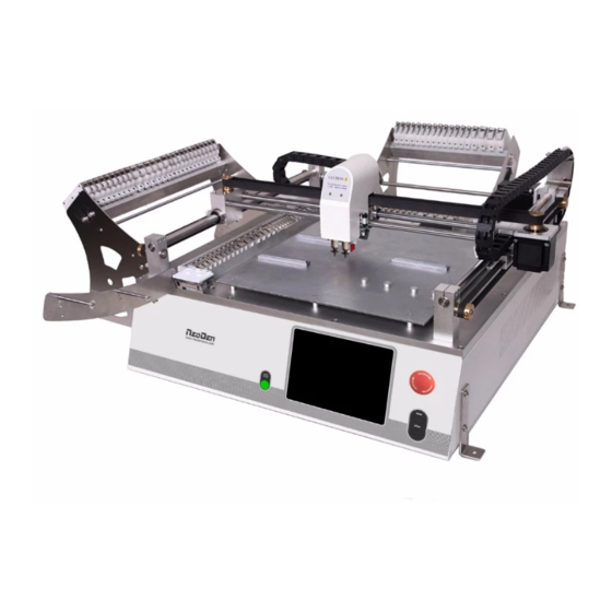
1.2. Structure of NeoDen 3V ⑥ ⑦ ⑧ ⑨ ⑩ ⑪ ⑫ ⑬ ① ② ③ ④ ⑤ ①:Start/Pause Button ②:On/off Button ③:Emergency Button ④:USB Connector ⑤:Fixation Holder ⑥:Head ⑦:Needle ⑧:Nozzle ⑨:Backward Fixed Block ⑩:Feed Chute ⑪:Peel Box ⑫:Vibration Feeder ⑬:Reel Holder... -
Page 8: Operation Flow Chart
1.3. Operation Flow Chart Flow Chart Remark Preparation Checking the working area whether it is safe or not Turn on Machine will start a 1-2 mins self-inspection process after Initialization boot-up. The head will travel along in X&Y axis. It will enter the operation page once finished. -
Page 9: Procedure For Making A Programming File
1.4. Procedure for Making a Programming File Start Edit See P5 PCB feed setting See P5 Panelized PCB first chip setup See P6 Chip list settings See P12 Mark point settings See P16 Feeder settings See P20 Save and cancel Select a file and start working Note: Above the procedure for making a programming file, the basic procedure of manual programming and importing coordinates file directly are similar. -
Page 10: Edit On The Operation Interface
2. Edit on the Operation Interface 2.1. PCB Information Interface See below Fig.: Edit Interface Create a new file or choose a file and enter the edit page 2.1.1. PCB Feed Setting Function: This part is used to confirm the feeding place, the first edit item in manual program. Feed the PCB to the estimated position and adjust it by click”Align”... -
Page 11: Panelized First Chip Setup
2.1.2. Panelized First Chip Setup Function: This is mainly to determine the first component position on single or panelized PCB. The principle is to collect and calculate the data of each board’s relative spacing, in order to achieve the effect of the actual placing. 2.1.2.1. - Page 12 After saving the coordinate, the screen will automatically turn back to “PCB information” . Click “Create panelized list” to get the information of this board. Now we’ve finished setting of first component of Single board.
-
Page 13: Panelized Board
2.1.2.2. Panelized Board The sequence is same to single PCB, but please pay some attention to several points below. The row and column is determined by the positioning of PCB on working area. The horizontal direction is the column. Enter data in the row and column. About the data collection of “left bottom”... -
Page 14: Mirror Board
2.1.2.3. Mirror Board Mirror board includes row panelized PCB and column panelized PCB Row panelized: several same PCBs are arranged in horizontal direction, and the nearby rows are mirrored Column panelized: several same PCBs are arranged in vertical direction, and the nearby columns are mirrored No.1 red areas are original ref No.2 yellow areas are original boards No.3 blue area is mirror ref... - Page 15 No.1 red areas are original ref No.2 yellow areas are original boards No.3 blue area is mirror ref No.4 light blue areas are mirror boards Based on actual board to choose an applicable model of panelized mode. Image left side is the arrangement way of mirror board and right side is the mirror board showing on computer.
-
Page 16: Pcb Angle Correction
2.1.2.4. PCB Angle Correction PCB angle will influence the accuracy of mounting. The angle more closer to 0 degree the better, and the angel deviation need to be within 1 degree. The angle of PCB is generated according to panelized PCB coordinates, but we can also adjust the angle by manual. -
Page 17: Component Setting
2.1.3. Component Setting 2.1.3.1. PCB Mark Setting Function: After completing setup of the mark points, with which the machine can locate the position of PCB and identify the set up mark points, so that the next step can be followed Mark Point on Single PCB ... - Page 18 Manual Programming When it’s in Manual Programming status, the function “Alignment” of Mark will be effective. Click on it, the camera will go and collect the coordinate of mark, save it and go back. (Note: if the mark point is far away, please use Overall movement to find it) Align by manual:if there is no mark point on PCB, you can choose this mode.Note:Select two components,the first one and the other one which can be recognized easily and far from the first component as Mark point.After...
-
Page 19: Manual Programming
2.1.3.2. Manual Programming Select “Chip list” to start manual programming. Function: it’s used to display footprints, coordinates, angles and sequences of components. You can choose to manually add these information or import coordinates file directly. Chip List Setup First, tick the box in front of “Manual”, you will see an example of component in chip list. You can click ”Align” to locate this component’s position and revise it accordingly. -
Page 20: Re-Edit
You can use Nozzle 1,Nozzle 2,needle to for workbench movement. Or you can use down-looking camera for visual minor adjustment. Locate the component’s center as coordinates, click “Save” and return to Chip list. Then you can fill the left information of components(note: designator, package, foot print and angel. The angel of horizontal component is 0°or 180°, the angel of vertical component can be different from +90°to -90°according to its polarity(Active Components) . -
Page 21: Import Pcb Coordinate File
After the board arrives to its destination, click “change to current position” button, it will pop up a message(refer to the image as below), click “Yes”, then the down-looking camera will start to recognize fiducial marks. After that, coordinates will be automatically converted to absolute values(machine coordinate) according to the location and angle of board. -
Page 22: Feeder Settings
2.1.4 Feeder Settings All component’s allocation should be operated in this interface, such as selection of nozzles and feeders, pick-up position, alignment methods, etc. 2.1.4.1. Feeder Arrangement Left feeders (Feeder 1-25; Right feeders (Feeder 26-45). Special feeders (Feeder 46-55). There are two ways to setup feeders. Before installing tape&... - Page 23 Feed-box Information Setting Function: Adjust the feed rate of needle. Feed rate: It's the distance between two adjacent holes' centers on tape. You can change the needle feeding rate by change this value Feed speed: Adjust speed by changing its value against different components. Default value is 1. Feed test: After finishing above steps, user can click this item to test component feeding location.
- Page 24 situation, such as the actual 1 component is in 2 row, 1 column, then type into X2, Y1. Feeder Basic Information: Firstly click the “Align” under “Position” function, camera will lock the component position on the feeder, once the modification saved, Pick X/Y data will automatically change to the ones after alignment. Angle: default is 0 degree, support to modify the value to change the mounting angles for wholly feeder.
- Page 25 Vacuum value: used for vacuum test, value can be set against actual need. 10) Flash type: outside light 11) Skip: Once select this item, will skip all placement under this feeder. 12) Test way: there’re two test methods, Vacuum test /Vision test. 13) Vacuum test : Once “Vacuum test”...
-
Page 26: File Mount
2.2. File Mount First select one file, click”mount”, then you will enter into mounting interface, above picture is an example of one file in mounting. On the top-left corner shows mounting process, chip list---by the variation of white line, you can track process of mounting constantly. -
Page 27: Manual Test
2.3. Manual Test Function: Used for testing the basic functions, connection between software and hardware , details about testing as below:... -
Page 28: Placement Head
2.3.1. Placement Head Choose nozzle 1, nozzle 2, nozzle 3, nozzle 4 to test separately Turn left& Turn right, selected nozzles will rotate Blow, after click this option, air will blow-off from selected nozzle Suck, after click this option, suction action will appear from selected nozzle ... -
Page 29: Feeder Test
Up Looking Camera Photograph, after click this option will take a picture X Y step out recover&X Y Initialize, after click this, machine will recover to its original position and coordinates in system will initialize. Vibration feeder on, after select this option, vibration tray will vibrate ... -
Page 30: Factory Settings
2.4. Factory Settings Function, this part is for machine’ global parameter settings, any modified parameter will influence all mounting files, when modify this part please consider seriously. Especially the last page system settings, we suggest after using a period of time or under the guidance of our engineers then change its parameter.(Notice, before our machines leave factory, all parameter already be set and no need to change). -
Page 31: Feeder Configuration
2.4.1. Feeder Configuration Function: you can set up and test pick up position, needle position as pictures Position X, position Y: The coordinate position of nozzle ... -
Page 32: System Configuration
Align the pick up position: Click to enter the visual lock interface, select the center as best location, it automatically generate the XY coordinates after confirmation. Feed Value: Set the forward value of each feeder, default value is 4(Unit:mm),but for special components, ... -
Page 33: Nozzle Alignment
Upward Photograph Angle: If find all chip have same angle problem during the placement, can adjust value here(Temporary can't use) Upward Photograph Exposure: Adjust the brightness of the up-looking camera 2.4.2.2. Nozzle Alignment Find the” Align” button of each nozzle, click “Align” and choose nozzle center pos and then click “Lens rotation”, up-looking camera will shine for many times, finally “Save “... -
Page 34: First Trial And Test
Click “align” to enter following interface: Operation Step: Move the nozzle to any position above a PCB, stick one carbon paper on the PCB, click “Trail”, the nozzle and needle will go down to leave each trails automatically , then click “nozzle1”, use the camera to match the cross line to the trails center of nozzle 1 and needle, finally “save”... -
Page 35: Inspection Standard
2.5.3.3. Inspection Standard If there is any issue of specification, direction and polarity, please follow process file to amend. If the components are off, please adjust the file by following two methods If the placement effects of all components are off in the same direction, it would be the fiducial issues. Please resolve this issue by adjusting the coordinate of fiducials according to its value of deviation. -
Page 36: Structure And Maintenance Instruction
3. Structure and maintenance instruction 3.1. Structure Chart 3.1.1. Peel Box Fixation of Peel box Fix the peel boxes on support bar and plug wires into connectors one by one. And the ID of each peel box can be changed accordingly. Load Cover Tape Uplift the gear, while insert the cover tape into it and make sure the cover tape is flat but not kinked. -
Page 37: Tape Reel Loading
3.1.2. Tape Reel Loading While loading tape reels on reel rack, the position of each tape reel should be aligned with its peel-box and feeder. Methods of Tape loading:①Load the tape reel on reel rack;②Insert the tape into feeder;③Pull back the cover tape from feed outlet;... -
Page 38: Reference Of Nozzle Selection
Table 1-1 Nozzle Size CN040 CN065 CN100 CN140 CN220 CN400 CN750 Illustration Outer 0.8mm 1.0mm 1.8mm 2.0mm 3.6mm 5.0mm 9.0mm Diameter Inner 0.4mm 0.7mm 1.0mm 1.4mm 2.2mm 7.5mm Diameter 3.1.3.2. Reference of Nozzle Selection In order to ensure placement accuracy, please select nozzles according to the shape and size of components. Table 1-2 Size Comparison of Nozzles Model Recommendation(Imperial System)... -
Page 39: Maintenance
3.2. Maintenance 3.2.1. Reinforce Daily Maintenance P&P machine is a relatively complex, high-tech and high-accuracy device that requires a extremely clean working environment with constant temperature and humidity. Thus, it’s must to be strictly in accordance with regulations of the equipment to have a routine maintenance. 3.2.2. -
Page 40: Maintenance Of Device
3.2.4. Maintenance of Device Routine check and maintenance policy should be established. 3.2.4.1. Check Below Points Daily Inspection Items Temperature and humidity: temperature range from 20℃ to 26℃, humidity range from 45% to 70%. No stuff on dual rails or the whole placement area. Please check below No stuff on the fix camera lens. -
Page 41: Related Issues During Solder Paste Printing Process
3.2.5. Related Issues During Solder Paste Printing Process 3.2.5.1. Stencil Printer Technology Screen printing technology refer to using ready-made stencil, directly contact to the printer in a certain way, make the solder paste evenly flow on the stencil and then leak into the mesh through the holes. When getting the stencil away, solder paste had been covered to the printed circuit board solder graphics corresponding, thus complete the solder paste printing on the PCB. -
Page 42: Instruction About Soldering Printing
3.2.5.3. Instruction about Soldering Printing Excellent printing graphics should be uniform in both vertical and horizontal direction,full,clean all round, solder paste fill solder pad. Using above such printing graphics device, after reflow soldering,will get good welding effect then. Defects Reasons Issues Solutions Holes on the stencil not good...
Need help?
Do you have a question about the NeoDen 3V and is the answer not in the manual?
Questions and answers