
Related Manuals for NeoDen K1830


Summary of Contents for NeoDen K1830
- Page 1 NeoDen K1830 High Speed Pick and Place Machine User Manual Model: K1830 High Speed Pick and Place Machine Version: V1.0 Zhejiang NeoDen Technology Co.,Ltd.
-
Page 2: Table Of Contents
PLEASE READ THIS USER MANUAL COMPLETELY BEFORE OPERATING. THIS UNIT AND RETAIN THIS BOOKLET FOR FUTURE REFERENCE. 1. Equipment installation and precautions 1.1Machine Dimension..................4 1.2 Structure of Neoden K1830............................5 1.3Working Area Structure..............................6 1.4 Important Notice................................8 1.5 Operation flow chart...............................9 1.6 Flow chart of making a programming file........................ - Page 3 Feeder Brief Introduction............................45 11.2Installing tape and reel components..........................46 11.3Incorrect installation Samples:..........................47 11.3.1Nozzle................................49 12. Maintenance..................................50 12.1 Take effective measures to reduce /avoid malfunction..................50 12.2 Maintenance............................... 51 12.3 Related issues during solder paste printing process..................52 Zhejiang NeoDen Technology Co.,Ltd.
- Page 4 1. Equipment installation and precautions 1.1Machine Dimension Figure 1- Machine dimension Zhejiang NeoDen Technology Co.,Ltd.
-
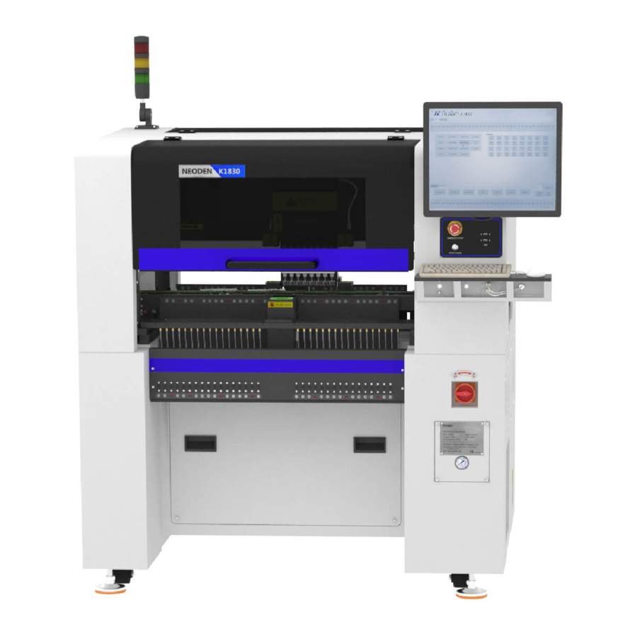
Page 5: Structure Of Neoden K1830
1.2 Structure of Neoden K1830 (5) (1) (2) (6) (7) (9) (8) (3) (4) (10) (11) (12) Figure 2-Ports and Appearance (7)USB port (1)Warning Light(Triple Color) (8)Pause button (2)Safety cover (9)Mouse keyboard bracket (3)Front Feeder Slots 1-33(Reference value) (10)Power Switch (4)Electric Feeder Port... -
Page 6: Working Area Structure
1.3Working Area Structure Figure 3- Top view of main mounting area Zhejiang NeoDen Technology Co.,Ltd. - Page 7 Figure 4-X-axis Beam Figure 5-Main Placement Head Camera Zhejiang NeoDen Technology Co.,Ltd.
-
Page 8: Important Notice
When installing the equipment, the equipment must be leveled; Correct shutdown: shut down the operating software and the system before turning off the main power switch; Figure 6-The air supply of the equipment shall not be less than0.6MP Figure 7- Feeder Pressure 0.55MP Zhejiang NeoDen Technology Co.,Ltd. -
Page 9: Operation Flow Chart
After the production is finished, reset the origin and prepare to Power OFF shut down; Shut down the system via computer, then power off the machine. Disconnect the electricity supply after the system being powered off. Zhejiang NeoDen Technology Co.,Ltd. -
Page 10: Flow Chart Of Making A Programming File
A. The basic procedure of making a programming file by manual programming or import coordinate file is similar, but there are two different parts: component list and fiducial setting. B. Please find the detailed operation steps of the differences on relative page. Zhejiang NeoDen Technology Co.,Ltd. -
Page 11: Pcb Editing
(8) Add a new file: click Add to open the input window, input the file name, and click OK. At this time, when the file list interface displays new files, the operation is successful. Zhejiang NeoDen Technology Co.,Ltd. -
Page 12: Pcb Forward Settings
In manual programming, this item is the primary editing item, and the board entry setting is as shown in the figure: 2.1.1 Mag Fixture Select tray to fix the board feeding mode, place the PCB to be installed in the proper position in the mounting area, and then click "top plate control" to fix the PCB. Zhejiang NeoDen Technology Co.,Ltd. -
Page 13: Pcb Eject Setting
Need set the PCB forward position before click “forward” Step:Click “Align”and enter the “align”interface,set the forward position according to the photo took by mark camera,and select “align method-nozzle 1”,then click “save”to save the forward position information. Zhejiang NeoDen Technology Co.,Ltd. -
Page 14: Panelized Pcb Edit
Click “single board setting”, you will see the “align” button of the SMD1 position that means the first component on the component setup. Click “align” to enter the vision align interface, we need find the first component that on the component list,generally we choose the center of the component, see figure Zhejiang NeoDen Technology Co.,Ltd. - Page 15 “align” of left bottom, find the left bottom panel that is nearest to the left side and nearest to the feeding position, then find the first component which on the chip list of this panel, align the center of this component. After saving the data, it will return to the “PCB information” automatically. Zhejiang NeoDen Technology Co.,Ltd.
-
Page 16: Mirror Board
“Align”. 3.1.3 Mirror board The steps of the Mirror board programming are similar with the Panelized board, but need pay some attention to several points below (1)Mirror board includes row panelized and column panelized Zhejiang NeoDen Technology Co.,Ltd. - Page 17 Save and Back:After align the center of components,click “save and back”to save the date. Close and Back:Refer to exit the current interface. Alignment Method:Include left mark camera,nozzle 1-8,right mark camera,choose the alignment method according to the actual situation,right side will show the real image by mark camera alignment. Zhejiang NeoDen Technology Co.,Ltd.
-
Page 18: Pcb Angle
Note:Generally use SMD1 coordinate in chip list and the one that is relatively easy to find far away from SMD1 as mark points,In this way, the relative placement effect will be Zhejiang NeoDen Technology Co.,Ltd. -
Page 19: Mark Point Information
Except for the coordinate of Mark point, the settings of min,max, light source, brightness, range, circle degree, mode, camera are same no matter automatically imported or manually imported. Mark point add and delete: Click “new”to add the mark point,click “delete”to remove the selected mark point you want. Zhejiang NeoDen Technology Co.,Ltd. - Page 20 Keep adding new component until the whole PCB finish. Please note the the stack and nozzle do not need to be edited manually. It can be set through feeder setting interface with ‘Assign all sequentially’ button to assign the information Zhejiang NeoDen Technology Co.,Ltd.
- Page 21 Move down: to move the selected component downward Move to head position: To move the selected component to the first row. Please notice the first row component must be the same as the first component to place on the PCB. Zhejiang NeoDen Technology Co.,Ltd.
- Page 22 (8) Batch create components Some circuit boards are relatively regular and easy in real editing situation. For this type of circuit board, we can generate coordinate in batch , the interface as shown in figure: Zhejiang NeoDen Technology Co.,Ltd.
- Page 23 We can see the panel has four rows and five columns. Fill in 4 rows and 5 columns in the dialogue, and align the three components(right top, left top, left bottom). The component degree will be based on actual situation. Click ‘create’, the machine will generate all the coordinate automatically. Zhejiang NeoDen Technology Co.,Ltd.
- Page 24 , as the quantity number is odd, we need to find 3 components that are in isosceles triangle, and then align the coordinates of those three points in turn. Click ‘create’ to generate 9 components’ coordinate in circle panel. Component point 2 Start Point Point Zhejiang NeoDen Technology Co.,Ltd.
-
Page 25: Feeder Setting
(3) Footprint library: The normal component information is saved in the footprint library including name, length, width, height, edge, pitch etc. Please note the detail information for the IC is necessary. The interface of footprint library as below: Zhejiang NeoDen Technology Co.,Ltd. - Page 26 “save and exit” will be OK. After that, you can select any feeder’s pick position as a test. While setting the pick position, the function of “Feeder open”/ “Feeder close” can help setting the cross position more conveniently. Zhejiang NeoDen Technology Co.,Ltd.
- Page 27 ”save and back”, the well-saved position’s X/Y coordinates will be automatically show up as fig. 4.2.1 (P.S.: pick position can be set one by one or be set by the scale setting, scale setting is more convenient). Zhejiang NeoDen Technology Co.,Ltd.
- Page 28 Accuracy: Generally normal resistor/ capacitor is default as high speed mode, do not need to modify it; For IC, please select high accuracy mode. Brightness: it refers to the brightness of component recognition (after be picked up) in assembly procedure. Zhejiang NeoDen Technology Co.,Ltd.
- Page 29 Pick test: after nozzle selection, click this button, the head will move to feeder position and finish the pick up step without any pause. Recognition test: After the “Pick test” with component be picked up, then click this “Recognition test” to show the Zhejiang NeoDen Technology Co.,Ltd.
-
Page 30: Nozzle Information
After above be set ready, click “component assign to feeder”, then component list will also be updated accordingly. Click save. 6.Nozzle Information This interface will record which kind nozzle be installed on each nozzle head. 7. Assembly Interface Choose the programmed file, click “Mount”, it will go into assembly interface as below: Zhejiang NeoDen Technology Co.,Ltd. - Page 31 (6)Right side buttons introduction: Start: Machine starts the current file’s assembly procedure. Step: operation for each single assembly procedure. Stop: Stop current assembly work. Config: press this button, a detailed configuration will pop out as below Zhejiang NeoDen Technology Co.,Ltd.
- Page 32 File edit: If there’re many times of pick failure or big placement offset, which need to re-edit the file, please directly press this button and it will directly turn to the file edit interface, after edit finished, save and back to the assembly interface will be OK. Zhejiang NeoDen Technology Co.,Ltd.
-
Page 33: System Setup
If the password needs to be changed, please login and click Change password. A window will pop out, enter the original password. Then follow steps to enter the new password. A successful window will pop out when it’s finished. Version: the current software version will be displayed below. Zhejiang NeoDen Technology Co.,Ltd. -
Page 34: Feeder Position Config
The left column refers to feeder No., Pick X and Pick Y refer to the coordinates of pick offset. After “click to align”, this interface will be displayed. Align the center of component (edge of tablet), then save it. Zhejiang NeoDen Technology Co.,Ltd. -
Page 35: Component Positions Setup
8.2 Component Positions Setup Zhejiang NeoDen Technology Co.,Ltd. - Page 36 Nozzle #8 , then check the offset between the round mark and the white crosshair, if it’s within 0.1mm, the trail is done. P.S. If the offset is overly beyond 0.1mm, please kindly contact NeoDen support team. Mark Left Position: to use the left camera align the round mark...
- Page 37 7.Flying Photograph Test: click ctrl+t shortcut keys to show this test function. Click to test, the central positions of nozzle 1-8 will be displayed. Select front camera, back camera, direction, speed before clicking photograph, a photo will be displayed after that. Zhejiang NeoDen Technology Co.,Ltd.
-
Page 38: Basic Configuration
8.Nozzle Height Set Zero Warning: this is only for factory setting. DON’T click before getting any instruction from NeoDen technical engineer. 8.3 Basic Configuration Zhejiang NeoDen Technology Co.,Ltd. - Page 39 Rails Feeding Time: the time it costs to feed a PCB from conveyor to Rail #1 when the machine is in continuous production. Safety cover: to prevent any body damage during picking and placing, enter value 1 to activate the function of cutting off power for motors when the safety cover is opened. Zhejiang NeoDen Technology Co.,Ltd.
-
Page 40: Manual Test
11.Nozzle Replace: click to replace nozzles, the head will move to its position for easier replacement. 12.Head Nozzle: click to test rotation, suction, blow and moving down functions of nozzle NO.1-NO.8. 13.Width Set: after the initialization of rails width, enter the expected width, click Width Set, the rails be widened accordingly Zhejiang NeoDen Technology Co.,Ltd. - Page 41 14.PCB Raise Initialize: initialize the PCB raise function 15.Width Initialize: initialize the width of rails back to zero. Zhejiang NeoDen Technology Co.,Ltd.
-
Page 42: First Trial And Test
●Frequent pickup failure. Some suggestions are listed below (1) The pick height is inappropriate, please revise the value after an inspection or a pick-test (2) The pick offset needs an adjustment, it should be aligned with the center of component reel Zhejiang NeoDen Technology Co.,Ltd. -
Page 43: Continuous Smt Production
(3) Once reloading the component during production, pay attention to the model, specification, polarity and direction of components. (4) Clear the reject box timely to avoid wasted materials stacked too high to damage the mount head Zhejiang NeoDen Technology Co.,Ltd. -
Page 44: Structure And Maintenance Instruction
11. Structure and maintenance instruction 11.1 Feeder Brief Introduction Zhejiang NeoDen Technology Co.,Ltd. -
Page 45: Installing Tape And Reel Components
(see figure 1).The tape should be closely matched with the gear, and the film should pass through the upper denomination groove (see figure 2) through two white guide wheels and then be sandwiched between two gears. Zhejiang NeoDen Technology Co.,Ltd. -
Page 46: Incorrect Installation Samples
Finish installing tape and reel components 图 4 For 12mm,16mm width feeder, the feed rate can be adjusted by adjusting the parameters of the feed regulator. 11.3Incorrect installation Samples: Incorrect setting of reel in reel storage (see figure.5) Zhejiang NeoDen Technology Co.,Ltd. - Page 47 Warning: when installing the feeder, if feel the hand press is not strong, or loose match in place, then it is forbidden to operate. Otherwise will cause feeder floating in the operation and collision problem. In case of this situation, please contact the after-sales department of our company Zhejiang NeoDen Technology Co.,Ltd.
-
Page 48: 1Nozzle
Extern 0.6mm 0.8mm 1.0mm 1.8MM 2.0mm 3.6mm 5.0mm 9.0mm Diame Inner 0.3mm 0.4mm 0.7mm 1.0MM 1.4mm 2.2mm 7.5mm Diame Type Special Special Special Special Special Special Special custom YX01 YX02 YX03 YX04 YX05 YX06 Model Zhejiang NeoDen Technology Co.,Ltd. -
Page 49: Maintenance
12.1.2 Requirements for operator ●Operator should get a basic operator training, which should cover fully all the skills and knowledge needed to safely operate the type of pick and place machine. Zhejiang NeoDen Technology Co.,Ltd. -
Page 50: Maintenance
②Checking if emergency button can work normally or not. Items check after ③Checking if placement head can move back to the origin. power on ④Checking if there’s abnormal noise while placement head move. ⑤Checking all nozzles vacuum pressure. Zhejiang NeoDen Technology Co.,Ltd. -
Page 51: Related Issues During Solder Paste Printing Process
(using stencil thickness and hole size to control in the actual operation). (3)Printed on the substrate of solder paste compared with required value, a certain deviation is permissible, the covering area of the solder paste on each solder pad should be more than 75%. Zhejiang NeoDen Technology Co.,Ltd. - Page 52 Wipe and clean stencil; Contamination of easily cause bridge times; Poor quality of solder replace solder paste; adjust the graphics connection paste; Shake problem when the machine getting the stencil way Zhejiang NeoDen Technology Co.,Ltd.
Need help?
Do you have a question about the K1830 and is the answer not in the manual?
Questions and answers
I have been trying to setup my pnp machine to pick components from trays but it always returns to the same point it already picked