
Subscribe to Our Youtube Channel
Related Manuals for NeoDen YY1


Summary of Contents for NeoDen YY1
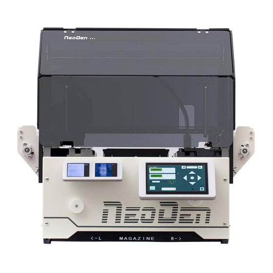
- Page 1 NeoDen YY1 Automatic Pick and Place Machine User Manual Model: NeoDen YY1 Automatic Pick and Place Machine Version: V1.0...
- Page 2 In order to make your experience with the NeoDenYY1 better, Note! please read this manual in detail before using the machine, fully understand the function and use of each part of the machine, and operate it according to the manual's requirements. Cautions 1.
- Page 3 Unpacking Instructions Please follow the instructions for unpacking: Step 1: Please remove the packing such as gin tape, pearl cotton etc. Step 2: Raise the upper part of the machine case. ① ② Step 3: Installation of acrylic cover.
-
Page 4: Table Of Contents
Catalog 1. Machine Overview ....................5 1.1 Machine Dimension ..................5 1.2 Machine Structure ................... 6 2. How to Quickly Place Your First Board ..............7 3. Software Interfaces Introduction ................9 3.1 Home Page and File List................... 9 3.2 File Editing Page..................... 10 3.2.1 Edit Component..................10 3.2.2 Edit Fiducial.................. -
Page 5: Machine Overview
1. Machine Overview Machine Dimension Figure 1-Machine dimension drawing... -
Page 6: Machine Structure
1.2 Machine Structure Figure 2-Schematic diagram of machine structure... -
Page 7: How To Quickly Place Your First Board
2. How to Quickly Place Your First Board Quick operation flow chart 1. You have two ways to generate placement files, export csv files through EDA design software or manually create new ones. 2. Before exporting the csv file, you need to set the lower left corner as the origin point (the Bottom layer is the lower right corner), as shown in Figure A. - Page 8 9. You can also get your PCB placement file by modifying the standard YY1 csv placement file on the computer. Note: The coordinates cannot have negative numbers, and the angle range is 180 degrees to -180 degrees;...
-
Page 9: Software Interfaces Introduction
3. Software Interfaces Introduction 3.1 Home Page and File List After initializing, it will turn to the Home Page ( Fig.YY1-01). Left side will show the files which exist in SD card and right side are three buttons for interfaces of “Manual Test”, “Feeder Settings”... -
Page 10: File Editing Page
3.2 File Edit Page As previously referred, the CSV coordinate file can be directly imported into machine through SD card for programming. What we must take notice is the correct CSV file will be automatically converted to the related format while loaded but if there’s error warning, it should be the file format wrong or the file was generated by some unsupported EDA. -
Page 11: Edit Fiducial
3.2.2 Edit Fiducial PCB will be fixed manually by the magnetic pin or bars and you also need to set a fiducial for helping recognition. Some tips for setting fiducials: 1. Fiducial requirement: round shape, it could be pads or holes with high contrast to the surrounding area (observed in the camera). -
Page 12: Panelized Pcb
3.2.3 Panelized PCB The way to set up the panelized information is very easy and intuitive. You just need to input the horizontal and vertical dimensions of the PCB, and the number of panels in horizontal and vertical directions. -
Page 13: Mount
3.2.4 Mount After you click Mount button, it will enter this interface. 1. Press Step button to enter the Preview mode, then the related buttons will turn green (active). 2. If you have set fiducial, the machine will go to recognize the fiducial before entering the Preview mode after clicking Step button. -
Page 14: Manual Test
3.3 Manual Test Click the orange button in the home to enter the Manual Test interface. You can click any buttons in this interface to test if each module is functional. (1)AIR VALVE 1/AIR VALVE 2: used to check if the valves are working.Please click to open the vacuum pump before testing the air valves. -
Page 15: Feeder Settings
3.4 Feeder Settings YY1 supports various types of feeder package, including: tape reel feeder, tube feeder,tray feeder,bulk feeder and strip feeder. The feeder setting include three main sections: tape reel feeder,flexible feeder and bulk feeder. 3.4.1 Tape Feeder You can enter the following interface for tape reel feeder setup. No 1-52 belong to tape reel feeder.Press the left or right button to select feeder, or directly enter feeder... -
Page 16: Flexible Feeder
3.4.2 Flexible Feeder You can enter the following interface for flexible feeder setup. No 53-80 belong to the flexible Feeder, press the left and right button to select the feeder, or directly enter the feeder number you want to edit manually. 1.Flexible feeder include vibration feeder,IC tray feeder ,strip feeder and customized IC tray feeder. -
Page 17: System Parameters
Please note: Any wrong parameter setting may cause the device to work improperly or reduce accuracy. The password is the chronological version of the machine, e.g. YY1 2022 version The password is 2022. The password is only used for avoiding mis-operation. -
Page 18: Basic Parameters
3.5.1 Basic Parameters Click the button Parameters, then entering the password, you’ll get the page as below. 1.Global speed will be changed if the setting revised by Global Mount Speed setting.The mount speed will be changed pro-rata if there is a speed value was setted in the working file already.Default value should be 70%,there may be some movement noise if the speed value be revised too high,better please set it based on actual request. -
Page 19: Head And Needle Calibration
should be the height once the nozzle reached the component of the tape reel.Meanwhile,the basis data can be obtained in the manual test by move the nozzle manually. 6.Photograph Delay means how long the camera waiting to photograph after the component move above the camera,increase the time value to prevent the vibration impacts for the photograph effects. -
Page 21: Up-Looking Camera Calibration
3.5.3 Up-looking Camera Calibration This function is mainly used to calibrate and adjust the center position of the camera. Follow the step-by-step operation as guided by the system online until the setup is completed. The guidance diagram for this setup operation is shown below. -
Page 24: Machine Operation Introduction
4. Machine Operation Introduction NeoDen YY1 The worktable is displayed as shown below: (1) Camera (2) Strip feeder tray (3) bulk feeder tray (4) nozzle change station (5) Tape feeder (6) Trash tray (7) Positioning strip (8) Stick feeder 4.1 PCB Fixing Methods Some common PCBs fixing method:... -
Page 25: Install The Tape Reel
For small PCB, fix a base board first, For particularly large PCB, remove the origin paste the blocking strip on the base screw, on feeder block have set positioning support, board to fix the PCB. for even larger PCB, if left feeder quantity is enough, remove the right side feeder. -
Page 26: Stick Feeder
Press here to unlock the feeder easily. frequently used components make them easier to locate. 4.3 Stick Feeder Adjust vibration 振动强度调节 Adjust 宽度调节 Installation for strip feeder 管装料的安装方式 Adjust the tube location to make sure the component can slide out a little bit more than one chip, it will be convenient for picking up the next chip. -
Page 27: Short Tape Reel Feeder
4.4 Short Tape Feeder 1. There is a needle in front of Strip feeder tray, but the hole of the strip into the needle, the components will be in the same position after change new strip. 2. Tear the strip film carefully. 3. -
Page 28: Nozzle And Auto Nozzle Replacement
4.5 Nozzle and Nozzle Change 4.5.1 Introduction and Selection of Nozzles In order to ensure the placement accuracy,please select nozzles according to the shape and size of components. Table 1-1 Nozzle Type Regular Regular Regular Regular Regular Regular Regular ular CN040 CN065 CN100 CN140 CN220... - Page 29 Nozzle selection reference In order to ensure the placement accuracy,please select nozzles according to the shape and size of components. Table 1-2 Model and minimum width comparison table Model Recommendation(Imperial system) CN030 0201 CN040 0402(optimal) CN065 0402、0603 etc. CN100 0805、diode、1206、1210 etc. CN140 1206、1210、1812、2010、SOT23、5050, etc.
-
Page 30: Auto Nozzle Change
4.5.2 Auto Nozzle Change The auto nozzle change device is located at the left front of the machine operator's console, as shown in the picture below. The auto nozzle change settings page, as shown below. 1. The head can be fitted with two nozzles at the same time and the nozzle station can also accommodate two nozzles, so it can support four different nozzle types at the same time in an uninterrupted placement process. -
Page 31: Vacuum Detection Module
complete mounting file, please check whether every nozzle replacement action are set correctly. The next nozzle is placed at the station where the previous nozzle was sucked away and left vacant position. When machine is running, you can visually see the real-time display value of air pressure on the upper two ends of the placement head and the two light strips on the outer housing, to judge the state of vacuum detection and working condition, as shown in the below picture. - Page 32 When the vacuum test is on, the corresponding light strip on the outer housing will light up, as shown in the below picture.
-
Page 33: Trash Box
4.7 Trash Box The trash box is located on the workbench of the machine. It can be easily picked up or installed under the condition of safety. Please note the direction when installing the waste box, with the arrow pointing upwards. -
Page 34: Magnetic Acrylic Cover
4.8 Magnetic Acrylic Cover The acrylic front cover of NeoDen YY1 can be opened and turned up as shown in the picture, which is convenient for observation and workbench operation. Please put the cover down before the machine starts to mount to ensure the safe use. -
Page 35: Machine Adjustment Guide And Maintenance
5. Machine Adjustment Guide and Maintenance 5.1 How to Adjust the Peeling Torque A damping ring with 2.5N torque is After removing these placed in the damping wheel. If you two screws, the damping want to reduce the torque, you can wheel can be easily replace it with the damping ring with removed or installed in... -
Page 36: How To Adjust The Belt Tightness
shape. 4. If you need the sheet metal with bigger pressure, you can use some tool to make it more bend. 5. Long time use will bring the tape feeder damping piece serious abrasion and lead to friction disabled, please replace new tape feeder damping piece. 5.3 How to Adjust the Belt Tightness Automatic preloading springs are installed on the X and Y axis belts. -
Page 37: Daily Maintenance
the small pliers tool. If the belt is loose, you can cut off a section of the belt and reinstall it. 5.4 Daily Maintenance SMT Pick and Place machine is a relatively complex high-tech and high-precision machine, which requires working in a constant temperature, humidity and very clean environment, and maintaining the habit of regular maintenance.
Need help?
Do you have a question about the YY1 and is the answer not in the manual?
Questions and answers