Table of Contents
Advertisement
Quick Links
Advertisement
Table of Contents

Subscribe to Our Youtube Channel
Related Manuals for NeoDen NeoDen10


Summary of Contents for NeoDen NeoDen10
- Page 1 NeoDen10 High Speed Pick and Place Machine User Manual...
- Page 2 Model:NeoDen10 High Speed Pick and Place Machine Version:V1.0...
-
Page 3: Table Of Contents
Catalog 1. Foreword..........................5 2. Precautions before using the machine..................5 2.1 Important Notes.......................7 2.2Machine Structure of NeoDen10..................9 2.3 Machine dimension.......................10 2.4 Working area structure....................10 2.5 Operation flow chart..................... 12 2.6 Flow chart of making a programming file..............13 3. File List Introduction......................14 4. - Page 4 6.3.1 Manual programming..................25 6.3.2 Import the coordinate file..................26 7. Feeder setting........................34 7.1 Function of feeder setting interface................34 7.2 Feeder Setting....................... 35 8. Nozzle Information....................... 39 9. Assembly Interface....................... 40 10. System Setup........................44 10.1Feeder Position Configuration..................45 10.2 Component Positions Setup..................47 10.3 Basic Configuration....................
-
Page 5: Foreword
14.3 Related issues during solder paste printing process...........63 1. Foreword Sincerely thank you for choosing NeoDen SMT machine.NeoDen10 is designed and used according to the following purpose---pick and place electric components on PCB. Please do not use this machine for other purposes. - Page 6 Figure A Anti-rust protective film Figure B:rail left and right drive ball screw; Figure C:Y-axis left and right movement linear guide; Figure D:rail left and right movement linear guide; Figure B...
-
Page 7: Important Notes
Figure C Figure D 2.1 Important Notes Warning of failure risk of camera identification, refer to figure 3 and figure 4: the following parts are forbidden to touch or strike. front IC camera back IC camera left mark camera right mark camera ... - Page 8 Warning of electric shock risk,be sure to follow the requirements below: Connect to the input power supply that meets the requirements of the machine, the electrical interface of the machine to the ground must be effectively grounded. Any time you enter the case or repair the placement head, you need to shut down the machine and cut off the power supply.
-
Page 9: Machine Structure Of Neoden10
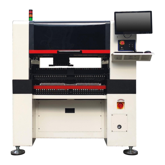
2.2Machine Structure of NeoDen10 (1) (5) (6) (2) (7) (8) (9) (3) (4) (10) (11) (12) figure 1-Ports and Appearance (1)Warning Light(Triple Color) (7)USB port (2)Safety cover (8)Pause button (3) Front Feeder Slots 1-33 (Reference value) (9) Mouse keyboard bracket (4)Electric Feeder Port... -
Page 10: Machine Dimension
2.3 Machine dimension figure 2 –machine dimension 2.4 Working area structure figure 3- Main placement head camera... -
Page 12: Operation Flow Chart
figure 4-top view of main mounting area figure 5-X axis beam(pull and push at the moving force point as above picture) 2.5 Operation flow chart Flow chart Note 1. The pick and place machine is a precision equipment. In the installation position of the machine, it is necessary to carry out horizontal correction before and after the equipment to prevent the uneven operation Start-up steps... -
Page 13: Flow Chart Of Making A Programming File
Keep the machine clean, daily maintenance of the nozzles assures high utility. 2.6 Flow chart of making a programming file Note: A. The basic procedure of making a programming file by manual programming or import coordinate file is similar, but there are two different parts: component list and fiducial setting. B. -
Page 14: File List Introduction
3. File List Introduction (1) Excel Open:The Excel table of the file can be modified directly in the table for some routine operations, simplifying the programming operation. (2) Edit: select a file and click Edit to enter the corresponding editing interface. (3) Processing: after editing the file and checking the correctness, select the file and click mount button. -
Page 15: Pcb Information Editing
4. PCB Information Editing In File List interface, select the file to edit,enter to PCB Information interface, as show in the figure: First, set the track width,adjust the track width according to the actual PCB width(usually actual PCB width plus 1mm),click Width Set,follow the prompt window to check whether back to zero condition are met.After back to zero, the track width will be adjusted.After placing the PCB on the track,gently push the PCB back and forth by hand to confirm that the PCB has a small gap of about 1mm in the track, so that the PCB can pass smoothly. - Page 16 Tracks width setting:Set correct PCB width value until the PCB can move smoothly PCB Feed Test:Put PCB to “Tracks Section 1”,Click “forward”, PCB will move to “Tracks section 2” and stop at the cylinder thimble position through the sensor,cylinder will raise the PCB, then thimble will go down, PCB feeding complete. (3)Long Tracks Select the “Long Tracks”on PCB Forward Setting interface, first enter the number of track segments(each segment corresponds to a file, the number of the file is corresponding to the number of the segment).Take 3-segment files as an...
-
Page 17: Pcb Eject Setting
position, cylinder will raise the PCB,then thimble 2 will go down,PCB feeding phase 2 is completed.After above placement is completed, the PCB in the waiting area is released, feed to cylinder thimble 3 position, cylinder will raise the PCB,then thimble 3 will go down,PCB feeding phase 3 is completed. 4.2 PCB Eject setting After click “Eject”no matter under Mag fixture or Track mode,the thimble will go down in “track section 2”,track section 2 and 3 begin to work and PCB will feed to back above the sensor position. -
Page 18: Single Board
5.1.1 Single board: Click “single board setting”, you will see the “align” button of the SMD1 position that means the first component on the component setup. Click “align” to enter the vision align interface, we need find the first component that on the component list,generally we choose the center of the component, see figure Click “Save and back”, it will back to the previous interface, click “create panelized list”... -
Page 19: Panelized Board
5.1.2 Panelized board The steps of the panelized board programming are similar with the single board, but need pay some attention to several points below (1)The row and column are determined by the positioning of PCB on working area. The direction along the rails is the column, the direction perpendicular to the rail is row, then please enter data in the row and column. -
Page 20: 3Mirror Board
After setup, click “create panelized list”, the panelized list will be generated accordingly in the blank. You can also double-confirm each position by clicking “Align”. 5.1.3Mirror board The steps of the Mirror board programming are similar with the Panelized board, but need pay some attention to several points below (1)Mirror board includes row panelized and column panelized Row panelized: several same PCBs are arranged in horizontal direction, and the nearby rows are mirrored... -
Page 21: Introduction Of Lock Interface
“PCB information” automatically. ●The data of “left bottom”on original board:on the alignment interface,find the left bottom panel,then find the component same as the component that aligned on the “right top”, align the center of this component. After saving the data, it will return to the “PCB information”... -
Page 22: Coordinate Information
Align method:Include left mark camera,nozzle 1-8,right mark camera,choose the alignment method according to the actual situation,right side will show the real image by mark camera alignment. Nozzle Down Test: When mark cameras are selected as the alignment mode, this function is gray and inoperable. When selecting nozzle 1-8, this interface turns black and can be operated. -
Page 23: Mark Point Information
(1) Panelized mark point It is mainly used for multiple identical PCB boards consistent of the whole board, when place every panel board, the machine will rescan small panel board’s mark point. (2)Single mark point It is mainly used for a single PCB board and multiple identical PCB boards consistent of the whole board (Notice: coordinate programming is done as a single board) Generally, need to select 2 or 3 mark points. -
Page 24: Component List Setting
Min, max value:It means the size of mark point, it has a floated value, which can prevent recognizing mark point wrongly. Flash: Light source divide into inner、 middle、 outer、 inner and middle、 middle and outer, whole lights. The user can make adjustments according to fiducial point recognition situation. -
Page 25: Manual Programming
6.3.1 Manual programming (1)Select manual programming; (2) The component information list displays multiple rows of sample components. First, modify the sample components: coordinate XY, click the position lock to enter the lock interface. According to the image presented by the Mark camera, find the corresponding component and confirm the center position coordinates, click save. -
Page 26: Import The Coordinate File
6.3.2 Import the coordinate file (1) Export the component coordinate information through computer by choosing metric system CSV format to the USB flash disk. (2) Plug the USB into the machine, do not choose the manual programming, import the processing file by clicking related layer file import button. - Page 27 (6)Convert to current machine coordinate After finish all editing operation, click convert to current position. It will pop up the above dialogue, click yes, the machine will recognize the fiducials automatically and convert all component coordinate to machine coordinate. After convert successfully, it will pop up a dialogue, click align to check if the components’...
- Page 28 For example: we can see the above picture which has a rectangular block and a circular block to form a small panel. We call such panel as submodule. We can generate the whole panel board through creating a submodule. Two ways to generate submodules: rectangle and circle.
- Page 29 图(2.1.3.2-6) When the quantity of component is odd: the component type will be the same. We can see that the panel has 9 components , as the quantity number is odd, we need to find 3 components that are in isosceles triangle, and then align the coordinates of those three points in turn.
- Page 30 (10 ) Auto programming: After import the coordinate file into component list (or manually programmed the coordinate file), click “Auto programming”, it will turn to the related interface: The first interface is”1/5 place order edit”, it is component list information, you can directly click “Next” The second interface is “2/5 New footprint edit”.
- Page 31 Detailed operations below: How to add these new footprint information to the footprint library? Three options for your selection: (1)Click “New footprint”, it will show a demo footprint line in the “Footprint library”, please manually type into the new footprint (showed on the right part in “New footprint list” area) information into it, then click any blank place, you’ll find the related information will disappear in the right part “New footprint”, that means it has been successfully added into Footprint library now.
- Page 32 (1)select a footprint from New footprint list (2)select a similar footprint from footprint library (3)click Add to footprint library or Add to alias library After click “Next”, it will turn to the third interface “3/5 nozzle assign edit”. Left part will show which type of nozzle be used, also will count the times it was used.
- Page 33 The final is “feeder stack edit”, it will show components were assigned to which stack position and what kinds of nozzle be used etc., please directly click “OK“ to finish the automatic programming. After that, you’ll find the information (placement sequence, nozzle assignment) in component list changed.
-
Page 34: Feeder Setting
7. Feeder setting All components’ setting on this files list, like: nozzle selecting, stack setting, the location of pick components, adjustment setting, and others components’ setting need to be finished here. We can see that No.1-33 stack on bottom line, No.34-66 stack on top line, No. -
Page 35: Feeder Setting
Batch processing pick up position and height: please select one stack to start setting (default start from the first assigned stack), at the same time, a real-time image will be showed as right side. Please set the red cross to the component center ( generally if the feeder is in off condition, red cross will be at the edge of feeder’s tape cover ), click “save and next”... - Page 36 ⚫ Right top XY: it refers to align the farthest component on the tray (generally take the component at right top as the final one on the tray, and take the component at left bottom position as the first one) ⚫...
- Page 37 Footprint/ Value: Component footprint/ value. Footprint refers to the footprint name like 0603, 0805, 1206 etc., Value refers to component data like 10K, 75Ω etc Pick Height:the height between nozzle and taps&reel’s surface on feeder. How to check pick height: Go to the Batch processing pick up position and height interface,enter the thickness of the component, click nozzle down (if the feeder is closed,after click nozzle down, the feeder will open),then manually check if the nozzle could reach the component.Adjustment can be applied according to the test.
- Page 38 Feeder type: there are pneumatic and electric feeders. Retry time:for those expensive components,you can set less retry time to avoid wasting. Feeding time: add feeding time for these components can’t be fed in right position during default feeding time. ...
-
Page 39: Nozzle Information
Feed Test: feeding component, this is used to test if the feeder could feed components smoothly. Size Measurement:after setting up the pickup position, pick height and nozzle, click Size Measurement, the machine will measure the length and width of component according to the recognized photo, if the dimension is correct, click to save the the data. -
Page 40: Assembly Interface
9. Assembly Interface Choose the programmed file, click “Mount”, it will go into assembly interface as below: (1) Left part is detailed chip list, and following the highlight blue will get a real-time assembly situation; On right top is the current assembly speed, you can drag the scroll bar to change it and the max is 100%; Throw and Rate will make a statistics for threw components and you can also check each feeder’s component pick failure rate then get which kind of component is easily pick failure, find solution to solve it. - Page 41 Place selected components: select the component which want to be placed in the placement list, check Mount, then select the component which want to start , click Start...
- Page 42 Place selected feeder:Tick feeder,click Start (5)View:After finish assembly work, users can select the corresponding components in the chip list, click View, photo 1 display the mounting situation of this component...
- Page 43 (6)The bottom side 8 display windows are real-time feedback for component recognition (7)Right side buttons introduction: Start: Machine starts the current file’s assembly procedure. Step: operation for each single assembly procedure. Stop: Stop current assembly work. Exit: once mounting work finished, please directly click this button and back to home interface. File Edit: In the process of mounting, if nozzle can't pick the component l for many times or big offset, Click Stop, analyze the related reason, and then click the File Edit , edit file without exiting the mounting interface, after finish modification,click Save and back to mounting interface...
-
Page 44: System Setup
Support simultaneously pick: once selected, the nozzle head with same pick height can be downward to pick components at the same time, it will greatly improve placement speed (It is recommended for component size bigger than 0603). (2) Rail continuous mounting: this is for PCB continuously feeding to realize automatic operation. (3) Pick up position optimization: once selected this function, nozzle head can automatically optimize the pick position ( It is recommended only for small components ). -
Page 45: Feeder Position Configuration
Right buttons functions: Config save: to click Save after changing the parameter Administrator login: to prevent any misoperation, this interface will be inactive and greys out. To make it inactive, Administrator needs to login. Change password: before Administration login in, this function is not visible. If the password needs to be changed, please login and click Change password. - Page 46 The left column refers to feeder No., Pick X and Pick Y refer to the coordinates of pick offset. After “click to align”, this interface will be displayed. Align the center of component (edge of tablet), then save it.
-
Page 47: Component Positions Setup
10.2 Component Positions Setup (Note:Password is required to activate the items to avoid misoperation, please contact technical engineer before calibrating.) 1. Fiducial Camera Relative Position Put a piece of label paper on the side of the track and dip the nozzle 1 into the printing paste or ink. ... - Page 48 P.S. If the offset is overly beyond 0.1mm, please kindly contact NeoDen support team. 2. function introduction: Mark Left Position: to use the left camera align the round mark Mark Right Position: to use the right camera align the round mark...
- Page 49 7. Automatic calibration Nozzle Position View: View the position of nozzles 1-8 in the center of the front IC camera. Click this button then 1-8 nozzles automatically perform actions and are displayed in this screen. Automatic nozzle positioning: The new version of the device enables automatic positioning of the nozzle with the front IC camera.
-
Page 50: Basic Configuration
Warning: This function is required to initialize after the height zero calibration of the placement head, this operation should be operated with caution, there is a risk that the equipment cannot be used, it is recommended that changes be made under the guidance of the manufacturer's engineers! Nozzle Height Set Zero Warning: This function is necessary for zero calibration of the nozzle height (very... -
Page 51: Manual Test
default brightness of Mark camera is 30, the default brightness of IC camera is 40, can be adjusted according to the actual situation Fiducial camera initial angle and IC camera initial angle. Warning: both data are set up before shipping, no extra adjustment is required. There is a risk to lead to malfunctional condition, please kindly contact technical engineer before operation. -
Page 52: First Trial And Test
(1)Feeder No.1-No.66: after loading tape reel on feeder, click the feeder to test its feeding function. (2)Alarm light: click it to test if the light could work correctly, the color should change from red, green to yellow by sequence. (3)Buzzer: click it to test if it works (4)XY initialize: click to have XY back to zero (5)XY Move: click this button to enter vision interface, the movement mode are optional, use the crosshair to move the head. -
Page 53: First Production Test
you can start to produce few boards. 12.2 First production test 1 Make a programming file 2 Test the file to pick and place components. 12.3 Component Inspection Inspection items Check if the specification, direction, polarity of components is aligned with what they should be. Whether the components are damaged or the pins are distorted. -
Page 54: Continuous Smt Production
with down-looking camera 2. If there are couple of issues occur during test, some other points need to be considered: Frequent pickup failure. Some suggestions are listed below The pick height is inappropriate, please revise the value after an inspection or a pick-test; The pick offset needs an adjustment, it should be aligned with the center of component reel slot rather than that of component;... -
Page 55: Structure And Maintenance Instruction
Once reloading the component during production, pay attention to the model, specification, polarity and direction of components. Clear the reject box timely to avoid wasted materials stacked too high to damage the mount head 13. Structure and maintenance instruction 13.1 Feeder Brief Introduction... -
Page 56: Installing Tape And Reel Components
(1)Front fixed buckle (6)Single-track wheel (2)Material-sendingwheel gear (7)Hand Shank (3)Press material cover (8)Tape coiling wheel (4)Locking Claw (9)Cylinder (5)Tail board (10)Snap joint cover 13.2 Installing tape and reel components figure 1 figure 2 1. Making the feeder in open status to wait for installing the tape reel ①Lift up the feeder fixing handle;②Press the material-sending handle with left hand ③meanwhile press the lamellule at right side of the feeder with your right hand;④loosen the material-sending handle, ensure the proper wrapped (see figure 1) then loosen the lamellule. -
Page 57: Incorrect Installation Samples
figure 3 see figure 3 3. Finish installing tape and reel components ( ) figure 4 The feeding rate can be adjusted by moving the adjustment steel piece. For 12mm, 16mm width feeder, the feeding rate could be adjusted to 12 or 16mm by flipping the steel piece (the distance between material belt holes is 4mm). (see figure 4) 13.3 Incorrect installation Samples:... - Page 58 Figure 5 2. The film is twisted, not tight enough, or the film is not between the white guide wheel and the black gear 3. Cautions: Strictly refer to the instruction manual to use the feeder, and non-standard operation is strictly forbidden Warning: when installing the feeder, if feel the hand press is not strong, or loose match in place, then it is forbidden to operate.
- Page 59 Warning: when installing the feeder on the equipment, make sure there is no foreign matter on the feeder fixed plate, and make the bottom surface of the feeder fully fit with the fixed plate. The handle is the main way to lock the feeder, so pls pay attention to protect this part.
-
Page 60: Maintenance
Type Special Special Special Special Special Special Special custom YX01 YX02 YX03 YX04 YX05 YX06 Model Illust ration Shape Table 1-2 size comparison of Nozzles Maintenance Model Recommendation(Imperial system) CN030 0201 0402(optimal) CN040 CN065 0402、0603 etc. CN100 0805、diode、1206、1210 etc. CN140 1206、1210、1812、2010、SOT23、5050, etc. -
Page 61: Take Effective Measures To Reduce /Avoid Malfunction
14.1 Take effective measures to reduce /avoid malfunction 14.1.1 Reinforce daily maintenance P&P machine is that high-accuracy device which requires a clean working environment with constant temperature and humidity, so it’s necessary to have a routine maintenance. 14.1.2 Requirements for operator Operator should get a basic operator training, which should cover fully all the skills and knowledge needed to ... - Page 62 Set pre-welding detection station (manual or AOI) In sum, P&P machine's running speed and placement accuracy still has limit. Peoples work is important to run machine on its proper role. So, it’s necessary to comply with effective measures to keep machine normal work, its placement quality and efficiency.
- Page 63 nozzle to check if it moves smoothly. Let each nozzle head up and down beyond the normal range. Vacuum Checking all nozzles’ vacuum pressure. If abnormal, please clean nozzles. pressure Positive Checking if the positive pressure normal. pressure Optical axis Checking whether it is covered dusk.
- Page 64 Shake problem when the machine getting the stencil way Dear users, the above is NeoDen10 operation instructions, if you have any questions, feel free to contact us, we will be happy to serve you. Thanks again for supporting NeoDen Tech.
Need help?
Do you have a question about the NeoDen10 and is the answer not in the manual?
Questions and answers