
Related Manuals for NeoDen 7


Summary of Contents for NeoDen 7
- Page 1 Hangzhou NeoDen Technology Co.,Ltd. 7th Generation High-Speed Pick and Place Machine User Manual Manufacturer: Hangzhou NeoDen Technology Co.,Ltd. Applicable Model: NeoDen7 High-Speed Pick and Place Machine Version: V1.01...
-
Page 2: Table Of Contents
2.1.1 PCB feed settings....................5 2.1.1.1 Mag Fixture....................5 2.1.1.2 Rail......................5 2.1.2 Panelized PCB origin (SMD1 coordinate)............6 2.1.2.1 Single board....................6 2.1.2.2 Panelized board..................7 2.1.2.3 Mirror board....................8 2.1.2.4 PCB angle correction................9 2.1.2.5 Skip marked panels................. 10 2.1.3 PCB fiducial setting................... 11 2.1.3.1 Single fiducial.................. - Page 3 Hangzhou NeoDen Technology Co.,Ltd. 2.4.3.2 Inspection method................... 27 2.4.3.3 Inspection standard..................27 2.5 Continuous SMT production..................28 3.Structure and maintenance instruction..................29 3.1 Structure chart....................... 29 3.2 Feeder Brief Introduction....................30 3.3 Installing tape and reel components................31 3.4 Incorrect installation Samples..................32 3.4.1 Nozzle.........................33...
-
Page 5: Brief Introduction
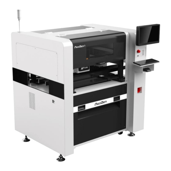
1.1 Product Introduction The seventh-generation model NeoDen7(Automatic universal visual pick and place machine) is NeoDen Tech’s independent product, with completely independent intellectual property. NeoDen7 has the advantages of fast speed, high accuracy, convenient operation, multiple feeders, high efficiency, stable performance, convenient and simple operation. NeoDen7... -
Page 6: Structure Of Neoden7
Hangzhou NeoDen Technology Co.,Ltd. 1.2 Structure of NeoDen7 ( 1 ) 12 inch high-definition (7)Pause button display (8)Mouse keyboard (2)Safety cover bracket (3)USB port (9)Conveyor Port (4)Universal wheel (10)Power Switch (5)Heavy load pedestal (11) Air source input (6)Emergency Button (12)Power port... -
Page 7: Operation Flow Chart
Hangzhou NeoDen Technology Co.,Ltd. 1.3 Operation flow chart Flow chart Note Checking the working area whether it is safe or not, Preparation whether the air source is normally connected and reaches the calibrated pressure value. Turn on Click the launcher icons, machine will start self-checking... -
Page 8: Flow Chart Of Making A Programming File
Hangzhou NeoDen Technology Co.,Ltd. 1.4 Flow chart of making a programming file Start Edit the file See P4 PCB feed setting See P5 Panelized PCB first chip setting See P6 Component setup See P12 Fiducial setting Pick up simultaneously Feeder settings... -
Page 9: Pcb Feed Settings
Hangzhou NeoDen Technology Co.,Ltd. Figure (2.1) 2.1.1 PCB feed settings Figure (2.1.1) Function: determine the PCB feed position. On the manual programming mode, it’s the primary edit item, see figure (2.1.1) 2.1.1.1 Mag Fixture When you select “Mag Fixture”, the function key of PCB feed setting and setting operation part will be banned. -
Page 10: Panelized Pcb Origin (Smd1 Coordinate)
Hangzhou NeoDen Technology Co.,Ltd. 2.1.2 Panelized PCB origin (SMD1 coordinate) Figure (2.1.2) Function: This is mainly to determine the first component on single or panelized PCB of manual program or imported file. The principle is to collect and calculate the data of each board’s relative spacing, in order to achieve the calculation of the real coordinate. -
Page 11: Panelized Board
Hangzhou NeoDen Technology Co.,Ltd. Figure (2.1.2.1) Click “ok”, it will back to the previous interface, click “create panelized list” button”, the data which on the panelized list will change. 2.1.2.2 Panelized board Figure (2.1.2.2) The steps of the panelized board programming are similar with the single board, but need pay some attention to several points below ●The row and column are determined by the positioning of PCB on working area. -
Page 12: Mirror Board
Hangzhou NeoDen Technology Co.,Ltd. component that aligned on the “left bottom”, align the center of this component, click save and cancel, it will return to the “PCB information” automatically. After setup, click “create panelized list”, the panelized list will be generated accordingly in the blank. -
Page 13: Pcb Angle Correction
Hangzhou NeoDen Technology Co.,Ltd. Figure (2.1.2.3) No.1 red areas are original ref No.2 yellow areas are original boards No.3 blue area is mirror ref No.4 light blue areas are mirror boards Based on actual board to choose an applicable model of panelized mode. Figure (2.1.2.3) left side is the arrangement way of mirror board and right side is the mirror board showing on computer. -
Page 14: Skip Marked Panels
Hangzhou NeoDen Technology Co.,Ltd. generated. (Note, the two points need to be paralleled) Under panelized PCB model, “PCB angle” is locked. You need to correct from panelized PCB to single PCB (1*1), after confirm the PCB angle, you can change back to panelized PCB model. -
Page 15: Pcb Fiducial Setting
Hangzhou NeoDen Technology Co.,Ltd. 2.1.3 PCB fiducial setting Figure (2.1.3) Function: After finishing fiducial setting, when the machine is working, the specific position and direction of PCB can confirm via setting fiducial. Only in this way the next step of mounting work can carry out. -
Page 16: Add Or Delete Fiducial
Hangzhou NeoDen Technology Co.,Ltd. Figure(2.1.3.3) ●Import the coordinate automatically status: the data collection of fiducial, which through PCB circuit board to find fiducial coordinate information directly, and input directly. Moreover, there are some information about min, max, light source and brightness in the fiducial list. -
Page 17: Component List Setting
Hangzhou NeoDen Technology Co.,Ltd. 2.1.4 Component list setting Function: display the information of mounting component, the mounting order of component, which can via manual programming or import process file to add component quantity and mounting information, see below figure (2.1.4), operation method: Figure (2.1.4) - Page 18 Hangzhou NeoDen Technology Co.,Ltd. We can move down-looking camera or nozzle 1 and nozzle 6, find corresponding component and confirm the component center coordinate, after clicking “save”, go back to main page, then input related component information (Notice: name refer to component bit number, specification refer to component value, footprint refer to common footprint name.
- Page 19 Hangzhou NeoDen Technology Co.,Ltd. input 2 rows and 2 columns, find 3 head components, after finishing generating it, the submodule is shown in the figure: we also can select stack, nozzle, name, specification and etc. to adjust in this page.
-
Page 20: Secondary Editing Of Components
Hangzhou NeoDen Technology Co.,Ltd. ② The way about how to generate the circle panel when the component number is double number: the project and rectangle of the “component type “are the same, we know it has 24 components by observation, the default angle is 0 here, input this value on your own. Because if the total component is double number, we only need to find two symmetry to align. -
Page 21: Import The Mounting File
Hangzhou NeoDen Technology Co.,Ltd. information, then we can edit and alter the list of components Figure(2.1.4.2) 2.1.4.3 Import the mounting file ● Preparing work: Firstly, importing the component information of the PCB which need to process in the computer, when importing it, select metric system, select CSV format, save it on USB flash disk, then plug it in the machine ●Do not choose the manual programming, click “file import top layer”, see figure (2.1.4.3), it... -
Page 22: Feeders Setting Page
Hangzhou NeoDen Technology Co.,Ltd. 2.1.5 Feeders setting page See figure (2.1.5) feeders setting page Function: all components’ setting on this files list, like: nozzle selecting, stack setting, the location of pick components, adjustment setting, and others components’ setting all need be finished here. - Page 23 Hangzhou NeoDen Technology Co.,Ltd. Figure (2.1.5.2-1) Function: mainly used to set up the picking up information of IC tray and vibration feeders, through change parameter information to finish the picking components’ work on the special stacks. horizontal numbers: mainly means how many components on X direction (A row has several columns of components) ...
-
Page 24: File Mounting
Hangzhou NeoDen Technology Co.,Ltd. situation to change the whole stack place angle. component footprint: through select some footprint information, during the vision adjustment process, the data here is which directly refer to the data in the library image adjustment: can choose flying adjustment, up-looking camera also cannot choose adjustment, which confirm by yourself. - Page 25 Hangzhou NeoDen Technology Co.,Ltd. Figure (2.2) First, select one file, click ‘mount’. You will enter into the mounting page, shown as figure 2.2. ●On the top-left corner shows process of mounting. You can track the process constantly by the blue line.
-
Page 26: Factory Settings
Hangzhou NeoDen Technology Co.,Ltd. (1) Support pick up simultaneously: Check this to make the nozzles with the same pick height picking the components simultaneously. This will raise the mounting speed much more. (2) Support step subdivide: Check this to subdivide steps to nozzles (3) Rail continuous mounting: Check this to make the rail feeding boards automatically, which will make the whole process continuously. -
Page 27: Feeder Configuration
Hangzhou NeoDen Technology Co.,Ltd. 2.3.1 Feeder configuration NeoDen7 adopt pneumatic feeders, you can setup the pick position and test in advance. Figure (2.4.1-1) shown as figure (2.4.1-1): parameters setting for all feeders. First list on left side is feeder No. -
Page 28: Nozzles' Positions Setup
Hangzhou NeoDen Technology Co.,Ltd. will show in the frame). Feeding test: click ‘feed’ button, the feeder will feed one component to check if it works. 2.3.2 Nozzles’ Positions Setup Figure (2.4.2) Function: this screen is mainly to correct nozzles’ position. -
Page 29: Ic Camera Position
Follow the same steps to get the trail of Nozzle #6, then check the offset between the round mark and the white crosshair, if it’s within 10mm, the trail is done. P.S. If the offset is overly beyond 10mm, please kindly contact NeoDen support team. 2.3.2.2 IC Camera Position... -
Page 30: Flying Camera Position
Hangzhou NeoDen Technology Co.,Ltd. Figure(2.4.2.2-1) Steps ●Click “Lens Rotation”, seconds later, you will get an overlapped photo of 360-degree rotated nozzle. ●Use the crosshair to align the centers of nozzle #1 to nozzle #6 (You can zoom in to see it clearly) ●Click “Save”... -
Page 31: First Trial And Test
Hangzhou NeoDen Technology Co.,Ltd. ●Click the “configuration” to enter photograph page in front of the nozzle 1 flying camera center position, click “photograph” and will appear 6 nozzle pictures. ●Align the cross to the nozzle center ●Waste box: set up the nozzle fling component position, which can according to demands to set up. -
Page 32: Continuous Smt Production
(5) The nozzle is damaged or has a crack (6) The size issue of nozzle would cause air leakage or insufficient suction. (7) The air hose is blocked or has a leakage problem, and even the pump has an issue. ●Frequently throwing components. Some suggestions are listed below, (1) Up-looking camera can’t take a clear picture of component due to brightness issue for... -
Page 33: Structure And Maintenance Instruction
Hangzhou NeoDen Technology Co.,Ltd. 3.Structure and maintenance instruction 3.1 Structure chart (1)Y-axis belt (6)Mounting head (2) Linear guide rail (7)Nozzle (3) Flying camera reflector (8)Tray holder (4)Three-sections auto rail (9)IC camera (5) Feeder fixing shelf (10) Anti-friction tank chain... -
Page 34: Feeder Brief Introduction
Hangzhou NeoDen Technology Co.,Ltd. 3.2 Feeder Brief Introduction Figure (3.2.1) ①Front fixed buckle ⑥Single-track wheel ②Material-sending wheel gear ⑦Hand Shank ③Press material cover ⑧Tape coiling wheel ④Locking Claw ⑨Cylinder ⑤Tail board ⑩Snap joint cover... -
Page 35: Installing Tape And Reel Components
Hangzhou NeoDen Technology Co.,Ltd. 3.3 Installing tape and reel components Figure (3.3.1) 1.Making the feeder in open status to wait for installing the tape reel ①Lift up the feeder fixing handle;②Press the material-sending handle with left hand ③meanwhile press the lamellule at right side of the feeder with your right hand;... -
Page 36: Incorrect Installation Samples
Hangzhou NeoDen Technology Co.,Ltd. Figure (3.3.3) For 12mm,16mm width feeder, the feed rate can be adjusted by adjusting the parameters of the feed regulator. (see figure.3.3.3) 3.4 Incorrect installation Samples 1. Incorrect setting of reel in reel storage (see figure.3.4.1) Figure (3.4.1) -
Page 37: Nozzle
Hangzhou NeoDen Technology Co.,Ltd. 3.Cautions: Strictly refer to the instruction manual to use the feeder, and non-standard operation is strictly forbidden. Warning: when installing the feeder, if feel the hand press is not strong, or loose match in Feeder fixed mount place, then it is forbidden to operate. - Page 38 Hangzhou NeoDen Technology Co.,Ltd. Table1-1 Nozzle Type Regular Regular Regular Regular Regular Regular Regular Regu CN030 CN040 CN065 CN100 CN140 CN220 CN400 Model Illust ration Extern 9.0m 0.6mm 0.8mm 1.0mm 1.8MM 2.0mm 3.6mm 5.0mm Diame Inner 7.5m 0.3mm 0.4mm 0.7mm 1.0MM 1.4mm 2.2mm...
-
Page 39: Maintenance
Hangzhou NeoDen Technology Co.,Ltd. Table 1-2 size comparison of Nozzles Model Recommendation(Imperial system) CN030 0201 CN040 0402(optimal) CN065 0402、0603 etc. CN100 0805、diode、1206、1210 etc. CN140 1206、1210、1812、2010、SOT23、5050, etc. CN220 SOP series ICs、SOT89、SOT223、SOT252, etc. CN400 ICs from 5 to 12mm CN750 ICs bigger than 12mm... -
Page 40: Formulate The Measures To Reduce/Avoid Big Problem
Hangzhou NeoDen Technology Co.,Ltd. 3.5.1.3 Formulate the measures to reduce/avoid big problem The most easily appeared problem during work are placement wrong components and placement misaligned. Supply below measures for ref. ① It needs to check whether the components package is matched with related feeder. If not, please correct them. -
Page 41: Monthly Inspection
Hangzhou NeoDen Technology Co.,Ltd. workable or not. ⑦Checking if the board has been well fixed by magnetic bar and pins. 3.5.2.2 Monthly Inspection Items Detailed Inspection X/Y axis Make sure no abnormal noise while placement head moving. X/Y motor Make sure X/Y motors no overheating. -
Page 42: The Defects Of Solder Paste Printing, Reasons Andsolutions
Hangzhou NeoDen Technology Co.,Ltd. graphics and solder graphics should be consistent. (2) In general, keep unit area amount of solder paste about 0.8 mg/mm². For fine pitch components, should be 0.5 mg/mm² (using stencil thickness and hole size to control in the actual operation).
Need help?
Do you have a question about the 7 and is the answer not in the manual?
Questions and answers