Table of Contents
Advertisement
Quick Links
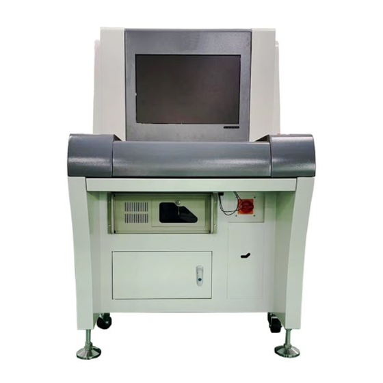
Automated Optical Inspection System
NeoDen Equipment
NeoDen 800
User Manual
V 3.2
To ensure the safe use of AOI equipment, please read this Manual carefu
lly before using it.
Do not operate this equipment without professional training.
Warning
Company website: www.neodentech.com
Zhejiang Neoden Technology Co., Ltd.
Copying prohibited
ⓒ Copyright Reserved 2021 Zhejiang Neoden Technology Co., Ltd.
Advertisement
Table of Contents

Subscribe to Our Youtube Channel
Related Manuals for NeoDen 800


Summary of Contents for NeoDen 800
- Page 1 To ensure the safe use of AOI equipment, please read this Manual carefu lly before using it. Do not operate this equipment without professional training. Warning Company website: www.neodentech.com Zhejiang Neoden Technology Co., Ltd. Copying prohibited ⓒ Copyright Reserved 2021 Zhejiang Neoden Technology Co., Ltd.
- Page 2 Company, copy of information of this Manual in part or in full is prohibited, with the exception stipulated by the Copyright Law that copy is required by normal use of software. Neoden is the trademark of Zhejiang Neoden Technology Co., Ltd. Microsoft EXCEL/Word/PowerPoint, SQL Server, Windows 95/98/2000/NT/XP, and Windows for workgroups are registered trademark of Microsoft Corporation.
- Page 3 Please move the equipment with effective packaging materials and power protection. Failure to take appropriate safety measures may result in personal injury. Warning This equipment complies with the wireless interference prevention standards of industrial/commercial area. The use of this equipment in the vicinity of residential regions may cause interference to the signals received by radio or television and may affect the functions of medical equipment.
-
Page 4: Table Of Contents
Contents Chapter I Preface........................1 Chapter II Main Uses and Scope of Application of Equipment..........2 Chapter III Working Conditions of Products................3 Chapter IV Main Technical Parameters...................4 Chapter V Main Working Principle..................6 Chapter VI Installation and Commissioning of Equipment............8 Chapter VII Equipment Adjustment..................9 7.1 Start-up procedure....................9 7.2 Camera focus correction...................10 7.3 Light source adjustment...................12... -
Page 5: Chapter I Preface
Chapter I Preface Thank you for choosing our Automation Optical Inspection (AOI). This professional equipment is mainly used to check the mounting and welding quality, installation status and solder paste printing effect of the components on the SMT production line, and display the unqualified products through display terminal. -
Page 6: Chapter Ii Main Uses And Scope Of Application Of Equipment
Chapter II Main Uses and Scope of Application of Equipment 2.1 Introduction of AOI 2.1.1 What is AOI AOI (Automatic Optical Inspection) is a new type of testing technology developing rapidly in recent years. It is composed of workbench, CCD camera system, electromechanical control and system software. -
Page 7: Chapter Iii Working Conditions Of Products
Chapter III Working Conditions of Equipment To avoid external factors affecting the normal use of this equipment, please follow the following items: 3.1 Operating environment of this equipment: The environment temperature of the equipment is: 10℃ to 35℃; the relative humidity is:35% to 80%. -
Page 8: Chapter Iv Main Technical Parameters
Chapter IV Main Technical Parameters Programming mode: automatic writing, manual writing, CAD data import, automatic component library matching Inspection mode: optimized inspection technology covering the whole circuit board. Jointed board and multi-mark with Bad Mark function Inspection type: whether paste printing has parts defects such as offset, lack of tin, excessive tin, open circuit, pollution;... - Page 9 Data transmission tool: supporting CAD, Excel, Txt and other commonly used formats Machine models: NeoDen 800, Weight of equipment: 550KG Dimensions of equipment: 980*980*1620mm Air pressure requirement: compressed air in pipeline is required, ≥0.49MPa...
-
Page 10: Chapter V Main Working Principle
Chapter V Main Working Principles This equipment performs inspection mainly based on optical principle and comprehensive use of principles color operation, color extraction, gray scale operation, image contrast. 5.1 Optical principle AOI's light source is composed of red, green and blue LED lamps. The three primary colors are combined into different colors. - Page 11 size, angle, offset brightness, color and position of the components, etc.) and outputs the images with the comparison results exceeding the rated error threshold through the display, and displays the specific positions of the images on the circuit board. 5.4 Principle of color extraction Any color can be mixed with red, green and blue in a certain proportion.
-
Page 12: Chapter Vi Installation And Commissioning Of Equipment
Chapter VI Installation and Commissioning of Equipment 6.1 Equipment installation This equipment is mainly divided into two parts, namely control system and image acquisition system. The equipment has been installed before leaving the factory. It is only necessary to confirm that all signal lines of the control system and image acquisition system have been correctly connected. -
Page 13: Chapter Vii Equipment Adjustment
Chapter VII Equipment Adjustment First, make sure that there are two small screw handles locked laterally on the side of the lens. The upper side is the aperture locking screw and the lower side is the focus locking screw. The aperture alignment scale is between 4 and 8, and the aperture locking screw is locked. 7.1 Start-up procedure Make sure that the emergency stop on the panel is not pressed, and the safety light curtains on both sides of the splint are not blocked. -
Page 14: Camera Focus Correction
7.2 Camera focus correction (the camera focus correction work will be corrected before leaving the factory, if the height of the mobile camera is different from the fixture height of PCB, it needs to be corrected) After starting AOI software, open [Working Mode]-[New Mode] in the upper left corner Make sure that the screw thread between the lens and the camera is locked, select a PCB and put it on the test platform, aim at the components with silk screen printing on the PCB directly below the lens, open [System Configuration]-[Illuminant Setting] in the menu bar, and... - Page 15 Then open System Configuration-Illuminant Setting as shown below: Loosen the focus locking screw, and gently rotate the lower end of the lens in one direction. At this time, the image will display the real-time state of sharpness change, and then rotate the lower end of the lens in the opposite direction.
-
Page 16: Light Source Adjustment
7.3 Illuminant setting (to be adjusted regularly) Place the randomly distributed standard color card directly under the light source. When the whole inspection window displays the color card part, it is as shown in the following figure. Open [System Configuration]-[Illuminant Setting] in the menu bar, select the appropriate adjustment reference value (generally select the reference value of 1), adjust the light source scroll bar on the left to set the feedback value of light source brightness to within ±... -
Page 17: Camera Lens Calibration
7.4 Camera lens calibration (the lens calibration will be completed before leaving the factory, and the camera needs to be calibrated again when moving the camera position) The lens calibration is to measure the vertical and horizontal deviation of the camera lens by specific software, and then compensate and correct it by software. -
Page 19: Chapter Viii Programming And Operation Of Equipment
Chapter VIII Programming and Operation of Equipment 8.1 Introduction of software operation methods Our AOI uses two categories: image contrast and color extraction, as shown in the following figure: [Region Method]: the principle of this algorithm is image comparison. [Qualified Reference Value] is similarity, which can be modified according to actual conditions. - Page 20 In this window, the user selects [Noumenon Extraction], and extracts the pixel regions that simultaneously meet the threshold values of three channels, namely the hue, brightness and saturation of pixels in the image interval, by setting their threshold values, and displays them visually in the lower right extraction diagram.
- Page 21 the OCV segmentation threshold through the scroll bar and select parameters, so that the image part to be extracted can be clearly identified, which is beneficial to improve the inspection stability. This algorithm is generally used for character inspection. [IC Short Circuit]: this algorithm divides the IC dense solder legs to calculate the number of IC solder legs and their length and width.
- Page 22 the straight line will not be included in the range of pin segmentation, so as to achieve the effect of filtering out the influence of the straight line. The setting interface switches the registered image and the real-time image to be inspected to help users compare and debug.
- Page 23 Users of preset extraction items in the system can modify them through the corresponding item fields under them. Color extraction sets the threshold values of hue, brightness and saturation of pixels in the image interval, extracts pixels that meet the threshold values of these three channels at the same time, and displays them visually in the extraction map.
- Page 24 the modified information at the same time. If there are multiple groups in the inspection frame, the user can switch between different groups by pressing the double-headed arrow in this interface, and press the “Delete” button to delete the current group (basic registration information cannot be deleted) [Feature Method] This algorithm is generally used to inspect the spherical surface of BGA, and is used to inspect the number, offset, missing, crush, short circuit of balls, as shown in the following figure:...
- Page 25 Set the hue, brightness and saturation of [Red] and [Blue] according to the method of color extraction. The extracted [Red] is the red in the middle of the ball, and the [Blue] is the color of tin on the ball. Then click [Only Apply to Current Inspection Frame]-[Exit] to return to the previous interface.
- Page 26 following figure: In this interface, the [Qualified Reference Value] is set. This parameter is the number of BGA balls in this algorithm. [Measurement] is used in this algorithm to measure the height and width of a single image and the distance between two images, as shown in the following figure:...
-
Page 27: Manual Program Editing
Firstly, according to the principle of [Color Extraction], the image to be measured is extracted. Then check the measurement options below and enter the allowed error. All the above algorithms are commonly used. 8.2 Manual program editing 8.2.1 New mode Open the AOI software according to {7.1 Start-up procedure}. - Page 28 First, click [Track Width Adjustment] in [System Configuration] in the menu bar, as shown in the following figure: (this figure is NeoDen 880) Select the corresponding track in this interface, and adjust the width of the track through [Up] and [Down] on the keyboard. (Note: Track 1 is fixed and not adjustable, and only Track 2 can be adjusted for the lower cover and monorail.) You can select [Jog] and then select the...
- Page 29 Click the in the lower right corner to let the camera automatically move to the lower left corner of PCB. On the basis of the image collected by the camera, confirm that the cross center point of the current camera is outside the lower right corner of PCB, as shown in the following figure: Because the position of track 3 is not fixed, the position of the lower right corner should be set for each program.
- Page 30 Then select [Rear Rail] in [PCB Zero Position] and click [Current Position] behind the right offset. At this time, the coordinates of [Right Offset] will change (right board is left offset). Then click [Save]-[Exit]. The lower right corner of the lower cover is the corner close to the right side of the track 2. As the track 2 is a moving track, it will be debugged according to the size of the board.
- Page 31 Then click [Operation]-[Set the upper right corner]. A dialog box will prompt: {Please extract the image of the whole PCB!}, click [Confirm]. Note: the above process of determining the lower right corner and upper left corner of PCB is only applicable to the left board placement direction.
- Page 32 A dialog box will prompt for confirming the model name and filing the name information, as shown in the following figure: Click [Yes], and the camera starts scanning the whole PCB image. After completion, a dialog box will prompt {Please set Mark Point}. Click [Confirm], and a dialog box for setting Mark point will appear, as shown in the following figure:...
- Page 33 In Mark Point #1, drag the box with the left mouse button to select one of the mark points of PCB bevel angle. Click Set, and adjust brightness/contrast and color mode to make the outline of Mark point image clear. Click Mark Point #2 to switch to the setting of Mark point of another oblique angle, as shown below:...
- Page 34 Note: the operation method of Mark point is region method, and the default value is 65, which can be modified according to the actual situation. Oxidation at Mark point can be inspected by noumenon extraction in region method, so the effect will be more stable. Click [Close] after Mark point setting is completed.
- Page 35 According to different components, select the corresponding box selection method: Non-polar single frame: generally outlining all non-polar capacitance and resistance inspection frames with specifications within 0402. It can also be used as the inspection frame for noumenon labeling of other components. Polar single frame: generally outlining all polar capacitors and resistors with specifications within 0402.
- Page 36 regular solder joints on both sides and complete display on one screen in the same window area) QFP: indicating the inspection frame of QFP IC. (it can only be used for QFP with regular solder joints on four sides and complete display on one screen in the same window area) If the component angle is not 45 degrees, check [Angle Registration] and pull the slider to rotate the image angle and then make frame.
- Page 37 After adjustment, the component frame can be made. Capacitance and resistance: you can directly click on the capacitance and resistance box below and hold down the left mouse button to make the frame, as shown in the following figure: The frame is based on the noumenon. After the noumenon is drawn, pad frames on both sides as well as silk screen frames in the middle will automatically generate (the color frame in the middle of the capacitor).
- Page 38 Select the type, manually enter the item number and remarks, and choose whether to deposit it in the public library (note: you can directly transfer it out from the public library when you execute other programs next time after depositing it in the public library), and then click [OK] to register After registering, if there are the same components in the same spilt, you can select the made component frame , right-click [Single-Point Copy], then move the mouse to the same component and click the left mouse button, and right-click to cancel the copy box.
- Page 39 Adjust the size of each frame, and then register the component according to the method of capacitance and resistance. If there are the same components, copy them in the same way. Triode: [Triangle] can be directly selected for making frame based on the noumenon of triode. As shown in the following figure: Adjust the size of each frame, and then register the component according to the method of capacitance and resistance.
- Page 40 Then divide each pin clearly by comparing with the above figure through [Area Threshold] and [Segmentation Threshold], or switch between [Registered Image] and [Image to be inspected]. (Note: If there is white silk screen printing between the white bottom plate and the corners and it is difficult to divide, you can check the [Whiteboard] below for division according to the situation).
- Page 41 Select a standard pin from the pins in the upper part of this interface. Then select a standard pin frame with the left mouse button, and click [Generate Pin] after making the frame. All pin frames will be automatically generated. As shown in the following figure: Then click [OK] to return to the previous interface.
- Page 42 Then check [OCV/OCR] algorithm in the property interface, which is generally used for characters. Check it and click [OCV/OCR] to enter the setting interface, as shown in the following figure: By debugging [Area Threshold], [Segmentation Threshold], [Filtering Threshold], [Corrosion] and [Filling], the characters can be clearly adjusted to the best. If it is black and white, check...
- Page 43 [Black and White Reverse] and then debug. When debugging is finished, click Apply-Exit to return to the upper interface, and then click [Apply]-[Close]. Select the noumenon of this IC by using the [Polar Box] (note: if the component has no direction, you can choose the [None-polar Box]) (note: if the IC is too large, you don't need to make the noumenon frame of the IC).
- Page 44 It is to merge components into a combination. After merging into a whole, the component is registered. After registering, select a standard pin from each side pin, click with the left mouse button to select the lead frame, right-click and click [IC Solder Joint Sharing Standard]. Pins on each side will share one pin according to this method.
- Page 45 shown in the following figure: According to the above method, edit all the components of this split board and then click [One-click Register] (shortcut key F2), as shown in the following figure:...
- Page 46 After registering, all the components forgot to be registered when editing the components will be registered. Then the component frame edited by this split editing will be copied to another split board. The specific operation is as follows: First, select the edited component split board in the left mouse button box on the thumbnail in the right, or directly click [Select All below] Right-click after selection, as shown in the following figure:...
- Page 47 Click [Copy Component] (0 degree indicates no rotation, 180 degree indicates copying by rotation by 180 degree). Move the copied frame to the approximate position of the next spilt, and then click the left key. As shown in the following figure: Then double-click the mouse to move the position of the camera to the copied spilt, and drag the whole components of the spilt to the correct position with the left mouse button on the diagram on the left side of the interface, and move them to the correct position.
- Page 48 After alignment, click with the left mouse button in the blank place where there are no components, and copy all the spilt according to this method. (When there are many spilts, it is recommended to copy them together) After copying all the spilts, click [Path Optimization] at the bottom of the interface, so that the running route of the camera will come out, and the camera will inspect according to the digital sequence of the path on FOV during later inspection.
- Page 49 Click [FOV Component Positioning] or [Overall Positioning] if the inspection frame of individual components is found to be incorrect after completion, The former is to position the component frame inside the camera frame only according to the noumenon frame, while the latter is to position the component frame on the whole PCB board according to the noumenon frame, as shown in the following figure: After positioning, click [File Management]-[Save] in the menu bar to complete the editing mode.
- Page 50 The upper left corner of this figure is the whole PCB image with crosshairs and marked positions. The upper right corner is the FOV enlarged image. The lower left corner is the components displayed by false alarm and the frame of each component displayed. The lower right corner is the standard image and the actual inspected image.
- Page 51 If the inspection frame is not on the component, drag it onto the component and click [OK] to finish. Click [Component Properties] if there is an error in adding pictures. As shown in the following figure: In the lower left corner of this interface, find the wrong picture by turning back and forth and delete it (note: the first image is the registered image of the component, which cannot be deleted.
- Page 52 adding dozens of pictures, you can slightly lower the [Qualified Reference Value] in this interface to achieve the effect of false alarm debugging. The calculation method is [Color Extraction]: first click [Component Properties]-[Color Extraction] as shown in the following figure: First, check [Image to be Inspected] to switch to the image to be inspected, and then see if the tin color is completely extracted.
- Page 53 First, check [Image to be Inspected] to switch to the image to be inspected. Then check whether each pin in the upper part of this interface is clearly divided and whether there is foreign matter in the middle, and then debug and divide the pins by [Area Threshold] and [Division Threshold] until each pin is clearly divided, then click [Save] to return to the upper interface and click [Close].
-
Page 54: Cad Data Import
Debug false alarm according to this method, It is suggested that debugging should not be finished at one time, but be carried out from the new inspection download after several debugging, which is helpful to the efficiency of false alarm debugging. Click [Enter] on the keyboard to return to the start interface of inspection mode, and click [Board Out] at the bottom of the interface to discharge AOI. - Page 55 After sorting out the coordinates, start editing the program. The method in the new mode is exactly the same as that in manual editing, so you can refer to the method of manual editing. After entering edit mode, click [Work Mode] -[CAD Import] in the menu bar, then select the CAD file to be sorted, and click [Open] as shown below:...
- Page 56 Then select [File Type] and [Unit]. If the first table name of the file is not sheet1, fill in the first table name. Then click [OK] to enter the following interface, as shown in the figure: Enter this interface and click [Select All]. Click the right mouse button at the coordinate position of thumbnail, as shown below:...
- Page 57 Rotate different angles in the frame, horizontally mirror and vertically mirror to match the position of coordinate points with components on PCB board, and then drag a coordinate point on the left figure to correct it, as shown above. Then edit the component.The selection of the component frame is the same as manual editing, as shown in the following figure: This interface will be prompted after the component frame is made.
- Page 58 number will be automatically generated at the same time. To facilitate editing, you can click [Component List] and then check [Show CAD Points Only]. At this time, the coordinates of components that have already been made in the list will not be displayed.
-
Page 59: Setting Of Bad Mark Skip Board
In the debugging mode, the false alarm debugging is implemented as that in the manual editing. 8.4 Setting of bad mark skip board After the program editing and false alarm debugging are completed, the skip board can be set. Enter [Editing Mode] after false alarm debugging. Then click [Base Board Configuration] in the editing mode and open [Set PCB Bad Mark], as shown below: Click on [New Area], as shown in the following figure:... - Page 60 First, select a screen printing or through hole in the lower left spilt of PCB board, box this pattern in the left image of the interface, and then click [Set Image] to finish, as shown in the above figure. Box the single spilt of PCB in the lower left corner on the right thumbnail of the later interface, click [Add Sub Area] after the box is selected, and then click [Save]-[Exit] to finish, as shown in the following picture:...
- Page 61 Then you can set to skip directly when NG reaches the set ratio (the system defaults to skip directly when the false alarm ratio of a single spilt reaches 50%) After setting, click [Edit Area], as shown in the following figure:...
-
Page 62: Setting Of Id Mark
After entering this interface, check the same image defined in [New Area] on diagonal spilt (i.e., spilt in the upper right corner), and then enter the corresponding numerical value in front of [Copy] at the bottom of the interface according to the spilt arrangement. (Note: the new area shall prevail. - Page 63 and back sides of PCB board. After debugging the program with false positives, enter [Set PCB-ID Mark] from [Base Board Configuration] in the menu bar, as shown below: Then, select a fixed image from the whole PCB board, box it in the fact image on the left side of the interface, and click [Set], as shown above.
-
Page 64: Normal Inspection Operation
Then click [Yes] to open the program on the other side. When testing, the camera will first inspect the position of two ID Mark points. Upon inspection of that ID Mark, the corresponding program will be called for inspection. 8.6 Normal inspection operation After entering AOI software, adjust the width of the track corresponding to its board, and then adjust the lower right corner position of PCB board after the back rail and lower cover of double track need to enter the board according to the method of new program. - Page 65 Then select the corresponding model and file and click [Open File], as shown below: [ID Mark] should be made for double track, which will prompt the track corresponding to this program. After selection, it will prompt to import another program and then select its track. After opening, select [Inspection Mode] in [Working Mode] in the menu bar, as shown below:...
- Page 66 Do not check [Debug Mode] for normal inspection. Click [Start] or press [Space Key] on the keyboard and [Start Key] on the machine to start inspection. When there is a board at the board entrance end, it will automatically enter for inspection. After inspection, it will be automatically discharged.
- Page 67 After entering the false alarm interface, a board at the front end will continue to enter for inspection. When inspecting the next board, check the false alarm of this board to ensure the speed. As shown above, the top left is a thumbnail of PCB board, which is marked with the position of current false alarm.
-
Page 68: Chapter Ix Spc Database Processing
Chapter IX SPC Database Processing Open [System Configuration]-[System Composition] in the menu bar, check [Use Database], select [MYSQL DB], and click [….] to enter the path setting interface. Ten click [….] behind [NG Image Path] to find the database path, as shown in the following figure; After setting, the data tested every day will be saved in SPC database. - Page 69 The login password is: aoisupervisor. NG file path is as shown above. Then click save. General factory settings have been completed. After setting, you can query all kinds of reports in this SPC software, and query reports according to procedures, time periods and defect types.
-
Page 72: Chapter X System Parameter Setting
Chapter X System Parameter Settings In [Editing Mode], open [System Composition] in [System Configuration] in the menu bar, as shown in the following figure: Front rail/rear rail: setting the zero position of the front and rear rails respectively. Left offset: setting the position of the lower left corner when creating a new program. Right offset: setting the position of the lower right corner when creating a new program. - Page 73 Same-side inspection: matching with the previous board entrance direction and simultaneous entrance and exit in the same direction to achieve one-way entrance and exit and inspection in the same direction. Speed setting: enter the running speed setting of the camera by opening [Speed Setting] alone. FOV pixel size: the size of each image captured by the camera, in pixels.
- Page 74 This interface shows some basic options for AOI equipment, as introduced in the following part: Last Program Auto Load: prompting {Open the Previous Program} at startup Auto_load PCB Model (Barcode Gun): different boards will be tested after matching the opened program according to the barcode after scanning.
- Page 75 select to inspect its actual rotation angle by checking [Inspect Angle Offset]. If it exceeds the set allowable rotation angle, it will be reported NG. Selecting this function will slightly increase the inspection time. Save log file: if special system problems need to be eliminated, the user can choose to save the log file and hand it over to the supplier for technical analysis.
- Page 76 In the sub-interface, you can set the login user's authority and password. The authority is divided into [Administrator], [Programmer] and [Operator], and the password can be modified in [User Maintenance]. In the [Editing Mode], open [Bar Code Settings] in [Substrate Configuration] in the menu bar, as shown below:...
- Page 77 In this interface, you can set the bar code format and bar code area after checking [Start Bar Code], and the test data will be saved according to the bar code during the later test. In the [Editing Mode], open [MES Settings] in [Substrate Configuration] in the menu bar, as shown below:...
- Page 78 The format and path of MES upload can be set after [MES Upload] is checked in this interface. In the [Editing Mode], open [Register Default Settings] in [Base Board Configuration] in the menu bar, as shown in the following figure:...
- Page 79 In this interface, users can set the default value of each type of component frame when editing the program, and can modify the value according to their own needs to improve the efficiency of program editing.
-
Page 80: Chapter Xi Common Equipment Faults And Troubleshooting Methods
Chapter XI Common Equipment Faults and Troubleshooting Methods 1. Shake during machine operation Reason and solution: the level of the machine is not adjusted properly. Use a level meter to adjust the level of the machine and tighten the screws fixing the foot cup. The steps for adjusting the machine level are as follows: ①... - Page 81 Solution: open the back cover of the machine, use a multimeter to inspect, and lock the loose part. 5. Black screen of display Reason: the display power supply is not turned on or the signal line is not connected properly Solution: check the power and signal lines of the monitor.
- Page 82 straight. Reason 2: the incoming materials of components have been changed or the silk screen has been changed. Solution: re-register a new standard for current component and include it and the component standard into the same group. 10. Missing inspection of IC pin short circuit Reason 1:there is no short circuit inspection frame for IC pin.
-
Page 83: Chapter Xii Repair And Maintenance Of Equipment
Chapter XII Repair and Maintenance of Equipment 12.1 To ensure the normal operation of the equipment and prolong its service life, please perform the following regular maintenance work: a) At the end of the day, turn off the power supply of the computer and equipment, and suck the dust on the equipment table surface with a vacuum cleaner. - Page 84 2) Determining whether the PCB photoelectric sensor works normally The equipment is equipped with a photoelectric sensor at the rail inlet end, the left baffle cylinder, the right baffle cylinder and the outlet end respectively. Under normal conditions, when a PCB passes through the rail, the signal lamp color will changes. 3) Determining whether the mechanical limit switch works normally There is a mechanical limit switch at the end of the X axis and Y axis of this equipment, which can be checked and confirmed by multimeter.
- Page 85 Step 2: apply grease evenly on the surface of the screw rod with a special oil gun, and push the X/Y axis to move back and forth to absorb the grease. Step 3: if the slide block on the guide rail has an oil nozzle protection cover, take it off before filling.
- Page 86 12.3 3. Confirmation form of check process/results Inspection Responsible Check content Remarks result person Check whether the power supply is well wired and grounded. Check whether the power supply and signal wiring on the back of the host are in good contact.
- Page 87 computer. Check whether display works normally, whether buttons operated effectively, and whether there are scratches on the surface, etc. Clear the hard disk files that are not necessary for the equipment and store the files in categories. Open the machine condition monitoring window to check whether the origin signal, limit signal and in-place signal of the X axis and Y axis are normal.
- Page 88 results 1. In the table, ○ indicates normal situation, and " x " indicates abnormal situation Remarks: 2. In case of any abnormality, the abnormal situation, handling and results must be filled in and signed by the responsible department head for confirmation. Equipment maintainer: Approved by: Reviewed by:...
Need help?
Do you have a question about the 800 and is the answer not in the manual?
Questions and answers