Table of Contents
Advertisement
Quick Links
Advertisement
Table of Contents

Related Manuals for Access Flow2A


Summary of Contents for Access Flow2A
- Page 2 © 2016 ThyssenKrupp Accessibility BV All rights reserved. Specifications and illustrations are subject to change without prior notice. ThyssenKrupp Accessibility BV will not accept liability for any alteration or typing error. Subject to the exceptions provided by law, this publication and/or its contents may not be, whether entirely or partly, reproduced, copied, and/or published in print, by photocopying, on microfilm, electronically or in any other way without the prior written consent of ThyssenKrupp Accessibility BV.
-
Page 3: Table Of Contents
Table of contents Table of contents General __________________________________________________ 5 1.1 Introduction ______________________________________________________________ 5 1.2 Customer requirements _____________________________________________________ 6 1.3 Safety aspects ____________________________________________________________ 7 The rail ___________________________________________________ 8 2.1 Construction ______________________________________________________________ 8 2.2 Rail sections ____________________________________________________________ 10 2.3 Rail options ____________________________________________________________ 11 2.4 Charging contacts _______________________________________________________ 12 The chair ________________________________________________ 13 3.1 Construction ____________________________________________________________ 13... - Page 4 Table of contents 4.3 Power supply system _____________________________________________________ 34 4.3.1 System assembly __________________________________________________________________ 34 4.3.2 Switching the stairlift on and off ______________________________________________________ 35 4.3.3 Charging the batteries ______________________________________________________________ 35 4.3.4 The rail charging contacts ___________________________________________________________ 36 4.3.5 The transformer ___________________________________________________________________ 37 4.3.6 Fuses ___________________________________________________________________________ 37 4.3.7 Measurement points and led indications ________________________________________________ 37 4.4 The service board _______________________________________________________ 38...
-
Page 5: General
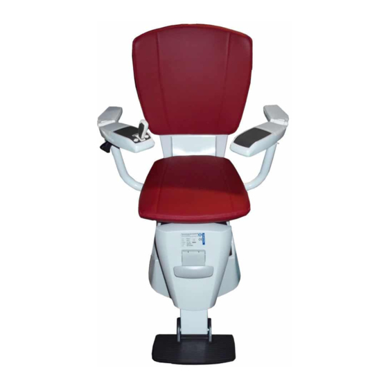
The Flow2A - Stairlift is a stairlift for seated persons and is a compact stairlift that fits most staircases: whether they are straight, curved or even spiral stairs. The stairlift can be positioned on either the inside or the outside of the stairs so that the available width of the stairs remains as usable as possible. -
Page 6: Customer Requirements
General The Flow 2A - Stairlift 1. Rail Mounting Fixtures 2. User Interface 3. Stairlift Motor System 4. Drive Rail 5. Chair 6. Arm Rest 7. Feet Rest support A. Swivel axis B. Level axis Customer requirements This section provides a summary of the possibilities the stairlift offers the customer. See the brochure Product introduction´... -
Page 7: Safety Aspects
General Rail coating The rail and chair base are finished with a durable powder coating. The powder coating applied to the rail is available in a variety of colours. On ordering the stairlift the customer selects the colour most suitable for the interior of the customer’s home. -
Page 8: The Rail
The rail The rail The rail is a round steel tube bent to shape to which a tooth rack is welded. Bogie rollers in the drive unit ensure that the drive unit moves evenly along the round tube. A gear in the drive unit engages in the teeth of the tooth rack. This provides the drive for the stairlift in the tooth rack on the rail. - Page 9 The rail Figure 2-3: Minimum distance from the stair threads In most cases the rail starts vertically on the floor at the bottom. Here the minimum distance from the front of the stair tread to the front of the rail is 175 mm. The standard version is equipped with a horizontal section of rail on the top landing.
-
Page 10: Rail Sections
The rail Figure 2-6: Emergency end stop Rail sections Depending on its shape, the rail can be divided into various sections. Figure 2-7: Inside and outside curves Curves in the horizontal plane are called inside curves (2) and outside curves (1). To avoid confusion: •... -
Page 11: Rail Options
The rail Rail options Longer runout A longer overrun than the standard-length overrun can be installed at both the top and bottom of the stairs. The maximum length is limited by the available space. Maximum rail runout dimensions: X= needed to install the chair Left or right rail The rail can be fitted on either the left or the right side of the stairs. -
Page 12: Charging Contacts
The rail The parking location must always be on a charging contact so that the batteries can be charged when the stairlift is not in use. Extra stopping places It is possible to define a maximum of 10 stopping places for the stairlift, including the parking locations and the stopping places at the ends of the rail. -
Page 13: The Chair
The chair The chair Construction Frame The chair consists of a frame on which a seat and a back cushion are fitted. The armrests can be folded up so that it is easier to get into and out of the chair. The chair can be fitted with straight or curved armrests, these are interchangeable by pair. - Page 14 The chair Footrest Figure 3-3: Short footrest The stairlift can be equipped with two types of footrests: • The standard type (default); • A short version, optional for situations in which the passage of a chair with standard footrest is hindered, such as in the case of a narrow stairwell.
-
Page 15: Swivel Seat System
The chair Swivel seat system The stairlift can be fitted with a fixed chair, a manual swivel seat or a powered swivel seat. Fixed chair With a fixed chair the chair is attached to the drive unit. To make it easier to step on and off, it is convenient if the seat is turned at the bottom and the top. - Page 16 The chair The chair with a powered swivel seat can turn both 110⁰ clockwise and 110⁰ counter-clockwise, depending on the rail and stairs. The electric motor is controlled by the electronics and the rotation is fully programmable in steps of 5⁰.
-
Page 17: Safety Mechanisms
The chair Safety mechanisms Obstruction safeguard The pivot under the chair is kept in a specified position during movement by springs (also with a fixed chair). This position is monitored by an opto coupler. If the chair is in the right position, the control is released. The maximum allowed swivel angles are not protected by limit switches or mechanical stops. -
Page 18: The Drive Unit
The drive unit The drive unit The drive unit The drive system and the system for keeping the chair base horizontal (level) is located in the drive unit. The drive unit consist of a number of boards, namely: • Control board •... - Page 19 The drive unit Figure 4-1: Schematic diagram...
- Page 20 The drive unit The control board The stairlift is a processor controlled system. The drive unit contains a control board that is accessible when the drive cover is removed. The control board has the following functionalities: • Supply and charge •...
- Page 21 The drive unit Safety sensor board The safety sensor board (1) is mounted on one of the bolts of the pedestal fixation elements(3). The safety sensor board will activate the stop of the lift when the horizontal angle is too far from zero or when it deviates to much from the chair sensor angle.
-
Page 22: The Memory System
The drive unit Receiver board The receiver board is located on top of the control board in the drive. The receiver board converts the signals coming from the user control unit, the call and park unit and the attendant control into a language that can be understood by the control board. Figure 4-4: Receiver board Service board The service board is located at the front of the drive unit directly under the service cover. -
Page 23: The Drive Motor System
The drive unit Call and park positions The following data can be stored on and or restored from a micro SDcard: Rail data: in total 99 different entries per stairlift Error data Maintenance counters Parameter data Firmware Call and park position Settings are changes in working memory. - Page 24 The drive unit Figure 4-7: Drive motor and brake Figure 4-8: Drive motor and brake in the drive unit The support system that is needed to carry the weight of the lift and guide it along the rail is shown in figure below (Figure 4-9).
- Page 25 The drive unit Figure 4-9: The bogie system The top bogie rollers (1) are spring-mounted so that the rollers can roll over the rail without any play and the stairlift remains stable in the rail even when there is no one sitting on it. The ball joints incorporated in the assembly ensure that the rollers always follow the profile of the rail.
- Page 26 The drive unit • An emergency stop at the ends of the rail This is an extra safety mechanism that prevents the stairlift being able to ride of the rail. The mechanical end stop will trigger the emergency limit switch opto coupler which is also used for the OSD. If triggered it signals the electronics to perform an emergency stop.
- Page 27 The drive unit To ensure that there will be no mismatch between the actual position and the position according to the pulse counter, the pulse counter is reset to the start position when the lift arrives at the lower charging contact. This contact is recognized by the system because the polarity of this charging contact is reversed with respect to all other charging contacts.
- Page 28 The drive unit Over speed device construction and operation The over speed device ensures that the stairlift comes to a halt if the speed is too high. Construction The over speed device consists of: 1. catchment gearwheel 2. teeth 3. cam ring 4.
-
Page 29: The Horizontal System
The drive unit If the speed of the chair exceeds 0.2 - 0.3 m/s, the idler will no longer be able to follow the shape of the teeth and it will come away from the top of the tooth. The idler will then not have sprung back in time to let the next cam pass. The idler will then be seized by a cam in the cam ring and forced against a locking pin (5) by the edge of the idler. - Page 30 The drive unit Levelling control Figure 4-13: Principle of level motor control system During normal operation the levelling control will attempt to maintain the chair base level within ±0.5⁰. When the chair base is tilted beyond ±2⁰, measured by the chair sensor, the levelling control will temporarily reduce the stairlift speed to reduce the influence of a moving stairlift on the levelling.
-
Page 31: User Control Components
The drive unit When the measured safety sensor angle is beyond ±7.6⁰ an error will be raised that causes an emergency stop and stop the level drive. The sensors have to be calibrated when the lift is installed via the service menu (mode -4-). User control components 4.2.1 User control units... - Page 32 The drive unit Attendant control The attendant control is an optional control unit that can be used by an attendant in case the chair-user is impaired to operate the wired user interface. Then the attendant can operate the stairlift. The operation of the attendant control is the same as the wired user interface.
-
Page 33: Receiver Board Operation
The drive unit 4.2.2 Receiver board operation Figure 4-15: Principle of user control components The receiver board is permanently connected to the wired user interface and to the remote controls. As soon as a command is given from any control, this command is translated by the receiver board into a language that is understood by the microprocessor on the control board. -
Page 34: Signals On The Control Units
The drive unit 4.2.4 Signals on the control units Each control unit is equipped with a LED. This LED indicates the status of the stairlift: Indication Meaning Constant green led Joystick has been operated and the stairlift is moving or will move Continuous flashing green led on armrest control No RF communication link possible 2 flashes of green led on armrest control... -
Page 35: Switching The Stairlift On And Off
The drive unit Because the stairlift works on batteries it can still be used when there is a power failure. The battery voltage is monitored by the microprocessor on the control board. With fully charged batteries at least 10 trips can be made, depending on various factors such as rail length, user weight and the age of the batteries. -
Page 36: The Rail Charging Contacts
The drive unit Charging assembly: 1. spring contacts 2. anti raise pin 3. forks The stairlift spring contacts (1) are incorporated in the charging assembly which is mounted under the drive unit. The spring contacts on the drive unit are connected to the charge circuit on the control board. The batteries are charged when the spring contacts of the drive unit make contact with the rail charging contacts. -
Page 37: The Transformer
The drive unit Figure 4-19: Charging contacts polarity 4.3.5 The transformer The transformer is prescribed by ThyssenKrupp: • Article number 07.72.40.100 • Voltage in 220BAC 50/60Hz • Voltage out 33VDC • Power out 82.5 Watt 4.3.6 Fuses The transformer is fitted with an automatic fuse. In case of overload the fuse ( a bi-metallic fuse) gets hot and switches the transformer automatically. -
Page 38: The Service Board
The drive unit The service board The service board is located at the front of the drive unit immediately under the covers. With this board it is possible to set the service settings of the stairlift. 4.4.1 Operation The installation handle At the factory a handle with a switch is fitted to the drive unit that is connected to the control board to ease riding the lift onto the rail. -
Page 39: Entering Service Modes
Entering service modes The Flow2A has 9 different modes: user mode -0- and service modes -2- till -9-. When the lift is switched on, the default mode is -0-. In this mode the lift can be operated by the joystick on the armrest or by the call and park unit or the attendant control. - Page 40 The drive unit This mode is also used to set the start point of the rail data table by moving toward the lowest charging contact until “rst” is visible in the display. Exiting this mode can be done by pressing the D and I button simultaneously. Mode -4- The level calibration mode, used to calibrate 0⁰...
- Page 41 The drive unit The middle digit is the number of the call and park unit. The left digit is the halt position for this unit and can be adjusted by using the D button (call action). The right digit is the park position and can be adjusted by using the I button (park action). In this mode only existing stop positions are shown.
- Page 42 The drive unit Miscellaneous options Restore settings and track data, by pressing and holding the E button for 2s, a file can be selected to restore (L00 till L99), selecting can be done by pressing the D or I button. When no files present or no SD card is inserted the display shows ‘L—‘.
Need help?
Do you have a question about the Flow2A and is the answer not in the manual?
Questions and answers