Table of Contents
Advertisement
Quick Links
Advertisement
Table of Contents

Related Manuals for Peak 212


Summary of Contents for Peak 212
- Page 1 Original TWO-POST LIFT Model:212...
-
Page 2: Table Of Contents
CONTENTS Product Features and Specifications ..........1 Installation Requirement .............3 Steps of Installation ………………………………………………..…………………………….5 Exploded View ................22 Test Run ..................27 Operation Instruction ..............28 Maintenance ................29 Trouble Shooting ..............30 Lift Disposal................30 Parts List ................31... -
Page 4: Product Features And Specifications
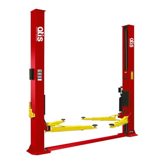
I. PRODUCT FEATURES AND SPECIFICATIONS FLOORPLATE CHAIN-DRIVE MODEL FEATURES Model 212 (See Fig. 1) · Dual hydraulic cylinders, designed and made on high standards, high quality seals. · Self- lubricating UHMW Polyethylene sliders and bronze bush. · Single-point safety release, and dual safety design. - Page 5 Arm Swings for Model 212 Fig. 2...
-
Page 6: Installation Requirement
II. INSTALLATION REQUIREMENT A. TOOLS REQUIRED Rotary Hammer Drill (Φ19) Carpenter’s Chalk Hammer Screw Sets Level Bar Tape Measure (7.5m) English Spanner (12") Pliers Ratchet Spanner With Socket (28 Socket Head Wrench (6 ... - Page 7 Equipment storage and installation requirements. The equipment should be stored or installed in a shady, normal temperature, ventilated and dry place. The equipment should be unload and transfer by forklift. Fig 4 D. SPECIFICATIONS OF CONCRETE (See Fig. 5). Specifications of concrete must be adhered to the specification as following. Failure to do so may result in lift and/or vehicle falling.
-
Page 8: Steps Of Installation
E. POWER SUPPLY The electrical source must be 3Kw minimum. The source cable size must be 2.5mm² and in good condition of contacting with floor. III. STEPS OF INSTALLATION A. Location of Installation Check and insure the installation location (concrete, layout, space size etc.) is suitable for lift installation. - Page 9 Parts box Floor cover Shipment Parts list Fig. 3. Take off the parts from upper and inside the column, then take out the parts box (See Fig. 9). Aluminum serial label Fig. 4. Loosen the bolts of the upper package stand, take off the upper column and remove the package stand 5.
- Page 10 Parts in the parts box (84) Fig. 6. Open the parts bag and check the parts according to parts bag list (See Fig. 12). Fig.
- Page 11 D. Lay down two columns on the installation site parallelly, position the powerside column according to the actual installation site. Usually, it is suggested to install powerside column on the front-right side from which vehicles are driven to the lift, then install the top plate (See Fig.13).
- Page 12 E. Position columns, install anchor bolts, check the columns plumbness with level bar, and adjusting with the shims if the columns are not vertical, Don’t tighten the anchor bolts at this time (See Fig. 14). Note: Width adjustment design, please set the width according to your need. Adjust the columns to vertical with the shims...
- Page 13 2. Using the prescribed rotary hammer drill, and drill all the anchor holes and install the anchor bolts. Then tighten the anchor bolts (See Fig. 16). Note: Torque of Anchors is 150N.m. Minimum embedment of anchors is 110mm. Fig. G. Install safety device (See Fig.
- Page 14 H. Lift the carriages up by hand and make them be locked at the same level (See Fig. 19). Safety device locked at the same level Fig.
- Page 15 I. Install cable According to step E to choose the width distance of your lift (See Fig.14) Note: Pass through the cable from the hole of the strength plate of one carriage to another carriage. 1. For width distance with 3829mm (See Fig.20) The strength plate of carriage...
- Page 16 2. For width distance with 3692mm 2.1. Pass through the cable from the bottom to the top of the carriage, the fitting of cable pass through the hole of the carriages and be screwed with two cable nuts. (See Fig. 21,22). Screwed with two cable nuts Cable...
- Page 17 2.2. Pass through the cable as arrow direction (See Fig. 22) Fig. 22...
- Page 18 J. Install cable of safety device (See Fig. 23). Note: Install the safety cable from the offside safety device, pay attention to the pass through direction. Install the safety cable from the offside safety device 2. According to the arrow direction to pass through the cable from offside safety device to power...
- Page 19 K. Install hydraulic power unit and oil hose assy. (See Fig. 24). View A View For columns distance 3000mm, use 1390mm oil hose. For columns distance 3137mm, use 1520mm oil hose. Fig.
- Page 20 L. Install floor cover (See Fig. 25). Choose different extension cover according to the columns distance. NOTE: Installation for 3137mm columns Use long extension cover to distance: connect the floor cover. Installation for 3000mm columns distance: Use short extension cover to connect the floor cover.
- Page 21 Adjust the Moon gear Locking the nuts after the moon gear and arm lock engaged well Fig. 2. Install toe guard. Fig. N. Tighten all the hydraulic fittings, and fill the reservoir with hydraulic oil. In consideration of Power Unit’s durability and keep the equipment Note: running in the perfect condition, please use Hydraulic Oil 46#...
- Page 22 O . Refer to the circuit schematic diagram and connect the power supply according to the motor nameplate. Note: To ensure the safety of the operator, the lift must be well grounded. When using a three-phase motor, pay attention to the forward and reverse rotation of the motor. 1.
- Page 23 2. 380V three-phase motor wiring 2.1、Circuit schematic (Fig 32) 2.2 Wiring steps (Fig 33) ○ The three wires (L1, L2, L3) of the external power supply are connected to the terminals labeled L1, L2, L3 on the AC contactor ○ The terminal labeled L1 on the AC contactor is connected to the 4 # terminal of the button switch, and the A1 terminal is connected to the 3 # terminal of the button switch.
- Page 24 2.3 Wiring diagram. Fig...
-
Page 25: Exploded View
IV. EXPLODED VIEW Model 212 Car in Fig. - Page 26 a. Exploded view of lifting arm assembly (10207062) Fig 36 Item Part# Description Qty. Item Part# Description Qty. M10*30 hex bolt Outer arm 10206048 11207012A φ10 washer Middle arm 10209039 11217337 φ10 washer Screw M8*12 10209022 10201149 Moon gear Inner arm 11206049 11217836 b.
- Page 27 c. Exploded view of the oil Cylinder (10207010) Fig. Cylinder parts list Item Part# Description Item Part# Description Piston Rod Adjustment Tube 20-1 11207027 20-8 10207029 Cylinder Piston Dust Ring 20-2 11207028 20-9 10217078 O-Ring O-Ring 20-3 10206069 20-10 10520058 Support Ring Head Cap 20-4...
- Page 28 d. Exploded view of power unit: (81513003/81513004) 220V/50HZ/1Phase 380V/50HZ/3Phase manual control manual control Fig. Single-phase 220V, 50Hz manual power unit parts list Item Part# Description Item Part# Description Rubber pad AC connector 81400180 41030055 Start capacitor Cover of Motor 81400130 81400287 Terminal Box AMGO Sticker...
- Page 29 Three-phase 380V, 50Hz manual power unit Parts list Item Part# Description Item Part# Description AMGO Aluminum screw 71150022 10420148 label screw Cover of Motor 81400300 80101022 Motor connecting Push button 81400363 10420070 shaft Manifold block Throttle valve 81400362 81400560 Washφ6 Relief valve 10209149 81400266...
-
Page 30: Test Run
V. TEST RUN 1. Adjust synchronous cable Use wrench to hold the cable fitting, meanwhile use ratchet spanner to tighten the cable nut. Cable Make sure two cables are with the same tension. If the carriage does not Synchronize when lifting, please tighten the cable nut of lower side carriage. -
Page 31: Operation Instruction
4. Test with load After finishing the above adjustment, test running the lift with load. Run the lift in low position for several times first, make sure the lift can rise and lower synchronously, the Safety Device can lock and release synchronously. And then test run the lift to the top completely. -
Page 32: Maintenance
8. Continue to raise the lift slowly to the desired working height, ensuring the balance of vehicle; 9. Push button “DOWN” to lower lift onto the nearest safety. The vehicle is ready to repair. To lower vehicle 1. Be sure clear of around and under the lift, only leaving operator in lift area; 2. -
Page 33: Trouble Shooting
4. Oil system is jammed 4. Clean the oil system lift disposal: When the car lift cannot meet the requirements for normal use and needs to be disposed, it should follow local laws and regulations. X. PARTS LIST FOR MODEL 212... - Page 34 Item Part# Description Qty. Note 11207001 Floor cover 11207002 Short extension cover 11207003 Long extension cover 11217019 Top pulley 10217020 Bronze bush for pulley 10209012 Hair pin 10209005 Self-locking nut 10209033 Washer 10209043 Hex bolt 11207055 Power side column 81513003/ Power unit 81513004 10209009...
- Page 35 Item Part# Description Qty. Note 10206036 Hair Pin 10217044 Arm lock 10217045A Spring 11217046B Left arm lock bar 11217046C Right arm lock bar 10209153 Arm lock bar ring 10201010A Chain connector BL646 10207015 Chain BL646 10209038 Hex bolt 11207016 Top plate assy. 11217037 Pin for bottom pulley 11217036...
- Page 36 Item Part# Description Qty. Note Cable 10207022 10209066 Cable nut Safety cable L=7450mm 10206149 10209049 Plastic small pulley 10207023 Oil hose 5/16*3210mm 10209060 90-degree Fitting for power unit 10209004 Rubber ring 10209003 Hex bolt 10207024 90-degree Fitting 11207035 Length fitting L=86mm 10420097 90-degree Fitting 10207026...
- Page 38 72222505 72126303 12/2019 09/2018...
Need help?
Do you have a question about the 212 and is the answer not in the manual?
Questions and answers