Table of Contents
Advertisement
Advertisement
Table of Contents

Related Manuals for Peak 209C


Summary of Contents for Peak 209C
- Page 1 Original TWO POST LIFT Model:209C/209CH...
- Page 2 CONTENTS Product features and specifications..........1 Installation requirement..............3 Steps of installation ..............5 Exploded view................25 Test run..................34 Operation Instruction..............36 Maintenance………………..............37 Trouble shooting.................38 .............38 LIFT DISPOSAL ......
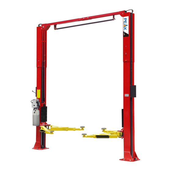
- Page 3 · Single-point safety release, and dual safety design . Clear-floor design, provide unobstructed floor use . Overhead safety shut-off device prevents vehicle damage · 4pcs of 3-stages arms with drop in rubber pads . Standard adjustable heights accommodates varying ceiling heights Fig. 1 MODEL 209C 209CH SPECIFICATIONS...
- Page 4 Arm Swings View For Model 209C 209CH 1285m 2528mm 1285mm Lifting Lifting Overall Minimum Model Lifting Height Overall Height Motor Capacity Time Width Pad Height 4000KG 1815-2044mm 3621/3821mm 3428mm 90-319mm 209C 3.0 HP 4000KG 1815-2044mm 4231/4431 mm 3428mm 90-319mm 209CH 3.0 HP...
- Page 5 II. INSTALLATION REQUIREMENT Rotary Hammer Drill (Φ19) Carpenter’s Chalk Hammer Screw srts Tape Measure (7.5m) Level Bar Pliers Spanner (12″) # # # # Wrench :(8 、10 、13 、14 Lock Wrench #...
- Page 6 B. Equipment storage and installation requirements. The equipment should be stored or installed in a shady, normal temperature, ventilated and dry place. C. The equipment should be unload and transfer by forklift. Fig. 4 D. SPECIFICATIONS OF CONCRETE (See Fig. 5) Specifications of concrete must be adhered to the specification as following.
- Page 7 Check and insure the installation location (concrete, layout, space size etc.) is suitable for lift installation. B. Use a carpenter’s chalk line to establish installation layout of base-plate (See Fig.6). Model 209C 209CH Fig. Click a line C. Check the parts before assembly.
- Page 8 4. Move aside the parts and check the parts according to the shipment parts list (See Fig.9, 10). Fig. Fig. Parts for 209C,209CH in the Parts in the parts box 50) shipment parts list 5. Open the bag 1 of parts and check the parts according to parts box list (See Fig.
- Page 9 6. Open the bag 2 of parts and check the parts according to parts bag list (See Fig. 12). Fig. 12 D. Install parts of extension columns (See Fig. 13). Fig.
- Page 10 This lift is designed with 2-Section columns. Adjustable height according to the ceiling height and connecting the inner and extensions columns. 1. 209C requirment: Ceiling height over 3850mm, can be both low setting/high setting, Ceiling height between 3650-3850mm, only avaiable low setting. Minium ceiling height: 3650mm 2.
- Page 11 F. Position columns (See Fig. 16) Position the columns on the installation layout of base-plate, Install the anchor bolts. Check the Columns plumpness with level bar, and adjusting with the shims if the columns are not vertical. Do not tighten the Anchor Bolts. 2850mm 3428mm Note: Minimum embedment of anchors is 100mm.
- Page 12 G. Install overhead top beam 1. With help of the hook of top beam, put one side of top beam on top of the extension column and connecting the top beam to extension column by bolts, tighten the bolts. Then assemble the connecting bracket (See Fig.
- Page 13 2. Assemble overhead top beam, tighten the columns anchor bolts (See Fig. 18) Fig. Tighten the anchor bolts with ratchet spanner with socket Note: Torque of Anchors is 150N.m.
- Page 14 H. Installing the limit switch control bar and limit switch (See Fig. 19). Loosen screw of drive rod for adjustment, tighten the screw after adjustment Adjust drive rod of limit switch Fig. 19 Limit switch connected with cable Connect the blue wire to terminal 11# on limit switch and terminal A1 on AC contactor of power unit Connect the brown wire to...
- Page 15 I. Install safety device (See Fig. 20 & Fig. 21 Fig. 20 Powerside Safety Device Fig. 21 Offside Safety Device...
- Page 16 J. Lift the carriages up by hand and make them be locked at the same level (See Fig. 22). Fig. 22...
- Page 17 K. Install cables 1. Low setting cable connection (See Fig. 23). Low Setting Cable2 Cable1 Cable2 Fig.
- Page 18 2.High setting cable connection 2.1. Cable pass through from the bottom of the carriages and be pulled out from the open of carriages, then screw the two cable nuts (See Fig. 24). High Setting Screw the two cable nuts Cable Connecting direction Cable connecting direction Fig.
- Page 19 2.2 Connecting cable for high setting (See Fig. 25). Cable 2 Cable 1 Cable 2 Fig.
- Page 20 L. Install hydraulic power unit and oil hose assy. (See Fig.26). Fig.26 Tighten all the hydraulic fittings, and fill the reservoir with hydraulic oil. Note: In consideration of Hydraulic Power Unit’s durability and keep the equipment running in the perfect condition, please use Hydraulic Oil 46#.
- Page 21 M. Install protective cover fig 27 Tighten the M6*30 bolt 1、 Tighten the M6*40 a little only. 2、 Install protetive cover, 3、 Then tighten the bolt Only use for 209C High setting Install protective cover for oil hose and protective pipe Fig 27...
- Page 22 N. Install safety cable (See Fig. Cable through Assembly safety cable pulley bracket from offside first. Safety Cable Finally connect the safety calbe to the powerside safety device. Fig.28...
- Page 23 O. Oil Hose & Protective Covers 1. Install Oil Hose. Note: Don’t cross the oil hose and safety cable together (See Fig. 32 & Fig.33). Tie the oil hose and wires together Safety Cable Oil Hose Wire Cable Offside Safety Device Powerside Safety Device Fig.
- Page 24 P. Install lifting arms and adjust the arm locks 1. Install the lifting arms (See Fig. 34). 2. Lowing the carriages down to the lowest position, then use the socket head wrench to loosen the socket bolt (See Fig. 35). Loosen the Bolt Use the 8 Socket Head Wrench...
- Page 25 R. Install electrical system Connect the power source on the data plate of power unit. Note: 1. For the safety of operators, the power wiring must contact the floor well. 2. Pay attention to the direction of rotations when using three phase motors.
- Page 26 Three phase motor 1. Circuit diagram (See Fig. 41) Three phase Fig. 2. Connection step (See Fig.42) a. The source wires (L1, L2, L3) are connected with terminals of AC contactor marked L1, L2, L3 respectively. b. Terminals 4# of control button is connected with wire 12#(brown wire) of limit switch;...
- Page 27 IV. EXPLODED VIEW Model 209C 209CH Fig. 43 Parts List Item Quantity Note Parts No. Description 209C 209CH 10206019 Snap Ring 10209012 Hain Pin 10209128 Washer 10209057B Bronzed bush for Pulley 11206020 Pulley 11206001C Power Side column 10209003 Hex Bolt...
- Page 28 10209004 Rubber Ring 10209005 Self Locking Nut 11217436 Safety device spacer 11217006 Safety device control handle 10217005 Plastic ball 10206023A Hex Nut 10420026 Spring Washer 10206006 Washer 11217004 Main Cam Lock 11217012 Safety device spacer 10209009 Cup head bolt 11217405 Power sider safety device cover 11217406 Offside safety device cover...
- Page 29 10201046A Rubber Pad Assy. 10420138 Socket Bolt 10209134 Rubber Pad 11680030C Support Frame 10209034 Lock Washer 10209039 Lock Washer 10209059B Anchor Bolts 10206500B Parts Box 10206501B 10201002 Hex Bolt 10206025A Form Cusion 10201005 Slit pin 11206129 Control Bar L=2400mm 11206025C Connecting pin for contol bar 10206013 Limit Switch...
- Page 30 11206203 Offside column 11209051B Stackable adaptor (1.5") Stackable adaptor (2.5") 11209052B Stackable adaptor (5") 11209053B 10217066 Hex Bolt 10217011 Hex Nut 10420045 Washer 10206064A Cable L=10030mm 10206064B Cable L=11250mm 10206132 Oil Hose L=4470mm 10206133 Oil Hose L=5080mm 10209060 90 degree fitting 10211016 T Fitting 10209064...
- Page 31 4.1 Lifting arm(10203156) : Fig. 44 Item NO. Parts No. Description Note 10206048 Socket Bolt M10*30 10209039 φ10 Spring washer 10209022 φ10 Washer 11206049 Moon Gear 11203146 Outer arm 11203147 Middle arm 10201149 Cup Head bolt 11201049A Inner Arm...
- Page 32 4.2 Cylinders (10217056) Fig. Item NO. Parts No. Description 30-1 10209069 O-Ring 30-2 10209070 Bleeding Plug 30-3 10209071 Support Ring 30-4 10209072 Y-Ring 30-5 10209073 O-Ring 30-6 11209074 Piston 30-7 11209075 O-Ring 30-8 11217076 Piston Rod 30-9 11209077 Piston Rod Fitting 30-10 10209078 Dust Ring...
- Page 33 4.3 Manual Power Unit (81513001/81513002) exploded view: 220V/50Hz/1Phase/manual 380V/50Hz/3Phase/manual Fig. 46 Part list for 220V/50HZ/1phase Part no Name 81400180 Rubber Pad 81400130 Start Capacitor 81400088 Running Capacitor 10420148 Cup head bolt 81400066 Capacitor Cover 81400363 Motor Connecting Shaft 80101013 Manifold Block 10209149 Spring Washer 81400276...
- Page 34 81400560 Throttle valve 81400266 Relief Valve 81400284 Plug 10720118 81400451 Release Valve Handle 10209020 Plastic Ball 81400421 Reelase Valve Nut 81400422 Self Locking Nut 81400449 Vavle Seat 81400567 Release Vavle 81400566 Check Valve 81400288 Oil suction hose 81400289 Oil return hose 81400364 clamp 81400263...
- Page 35 81400449 Valve Seat 81400567 Release Vavle 81400566 Check Valve 81400289 Oil Ruturn Hose 81400364 clamp 81400263 Oil tank cover 81400275 Oil tank Illustration of hydraulic valve for hydraulic power unit Oil return port Relief valve Release valve Check valve Throttle Oil outlet valve Handle for...
- Page 36 V. TEST RUN 1. Adjust synchronous cable (See Fig. 48) Press button UP to lift the vehicle carriages until the cable nut is higher than chain pulley and lock the two vehicle carriage in the same safety lock. Use wrench to hold the cable fitting, meanwhile using ratchet spanner to tighten the cable nut.
- Page 37 5. Test with load After finishing the above adjustment, perform a test run of the lift with a load. Run the lift in low position for the first few cycles, make sure the lift can rise and lower synchronously, the Safety Device can lock and release synchronously. And then test run the lift to the top completely.
- Page 38 VI. OPERATION INSTRUCTIONS Please read the safety tips vehicle carefully before operating the lift To lift vehicle 1. Keep clean of site near the lift; 2. Position lift arms to the lowest position; 3. To shorten lift arms; 4. Open lift arms; 5.
- Page 39 VII.MAINTENANCE SCHEDULE Monthly: 1. Re-torque the anchor bolts to 150 Nm; 2. Check all connectors, bolts and pins to insure proper mounting; 3. Lubricate cable with lubricant; 4. Make a visual inspection of all hydraulic hoses/lines for possible wear or leakage; 5.
- Page 40 VIII.TROUBLE SHOOTING TROUBLE CAUSE REMEDY 1. Button does not work 1. Replace button 2. Wiring connections are not in good 2.Repair all wiring connections condition Motor does not 3. Motor burned out 3. Repair or replace motor 4. Height limit switch is damaged 4.
- Page 41 Manual No.:72120608 Revise Date:2019/12...
Need help?
Do you have a question about the 209C and is the answer not in the manual?
Questions and answers