Table of Contents
Advertisement
Quick Links
Advertisement
Table of Contents

Related Manuals for Peak Amgo 414A


Summary of Contents for Peak Amgo 414A
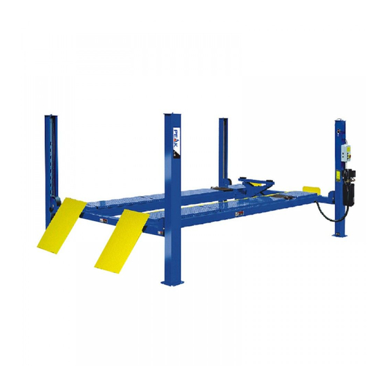
- Page 1 414A(A465A)
-
Page 2: Table Of Contents
CONTENTS Product Features and Specifications ............. 1 Installation Requirement ……………………………………………………………………………… 2 Steps of Installation …................ 3 Exploded View ................. 32 Test Run ……….................. 36 Operation Instruction ............... 38 Maintenance ................... 39 Trouble Shooting ................40 Parts List ..................41... -
Page 3: Product Features And Specifications
I. PRODUCT FEATURES AND SPECIFICATIONS ALIGNMENT 4-POST MODEL 414A FEATURES · Electric-air control operation system. · Mechanical self-lock and air-drived safety release. · Electrical hydraulic power system, cable-drived. · Non-skid diamond platforms. · Multiple turnplate pockets fit with different wheel base. ·... -
Page 4: Installation Requirement
II. INSTALLATION REQUIREMEN A. TOOLS REQUIRED Rotary Hammer Drill (Φ19) Carpenter’s Chalk Hammer Screw Sets Level Bar Tape Measure (7.5m) English Spanner (12") Pliers Wrench Set Lock Wrench , 12 , 13 , 14 , 17... -
Page 5: Steps Of Installation
B. SPECIFICATIONS OF CONCRETE (See Fig. 3) Specifications of concrete must be adhered to the specification as following. Failure to do so may result in lift and/or vehicle falling. 1. Concrete must be thickness 100mm minimum and without reinforcing steel bars, and must be dried totally before the installation. - Page 6 2. Open the outer packing carefully (See Fig. 5) Parts box Control box Drive-in Ramp Cross Beam Column Offside Platform Powerside Platform Shipment Parts List Fig. 5 3. Take off the drive-thru ramps and columns (See Fig. 6) Fig. 6 4.
- Page 7 6. Open the carton of parts and check the parts according to the parts box list (See Fig. 8) Fig. 8 7. Check the parts of the parts bag according to the parts bag list (See Fig. 9) Fig. 9 - 5 -...
- Page 8 C. Use a carpenter’s chalk line to establish installation layout as per Table 1 Make sure the size is right and base is flat (See Fig. 10). Note: Reserve space front and behind the installation site. 、 Car in Direction Use a carpenter’s chalk line to establish installation layout Fig.
- Page 9 D. Install cross beams (See Fig. 11, Fig. 12) Hole towards inside Fig. 11 Fig. 12 - 7 -...
- Page 10 E. Fix the anchor bolts 1. Prepare the anchor bolts (See Fig. 13). Spring washer Washer Fig. 13 2. Using the prescribed rotary hammer drill, and drill all the anchor holes and install the anchor bolts. Do not tighten the anchor bolts (See Fig.
- Page 11 2. Install safety ladders (See Fig. 16). This height should be the same for four safety ladders Safety ladder pass through the hole of the top plate, then tighten the two nuts. Fig. 16 G. Put the cross beams at the same height (See Fig.
- Page 12 H. Install powerside platform. 1. Put the powerside platform upon the cross beams by fork lift or manual, offset the cross beams to the outside till the pulleys of both platforms can set up into the cross beams , Install the powerside platform and screw up the bolts (See Fig.18) (See Fig.19) Offset the cross beam lean...
- Page 13 2. Assembly offside platform and slider block, check the plumbness of columns with level, adjusting with the shims if not, and then tighten the anchor bolts (See Fig. 20). 3-15 Using the Ratchet Spanner With Socket to tighten the bolts 3-16 3-14 Install the slider block...
- Page 14 J. Install cables (See Fig. 21). 1. Install the cable which has roll on the platform to the column as number. ○ ○ ○ ○ Cable Length 4104mm 11058mm 5810mm 9354mm (inc. connecting fitting) 161 5/8” 435 3/8” 228 3/4” 368 1/4”...
- Page 15 2. The cable pass through the cross beam to top plate of columns and be screwed with cable nuts (See Fig. 22). Cable pass through Cable pass through top between the big pulley plate and be screwed and tension pulley with cable nuts.
- Page 16 3. After cables pass through the pulleys under the platform, installing the Slack-cable bolts No.19 (See Fig. 23). Limit Slider cable ④ cable ② cable ② cable ④ cable ① cable ③ cable ④ cable ④ cable ③ cable ② cable ②...
- Page 17 K. Install oil-water separator, air solenoid valve, control box and power unit 1.For Electric control air-operated four post lift (See Fig. 24). 24 25 26 27 28 30 22 Air inlet Air outlet Oil-water separator and Air Solenoid Valve Fig. 24 - 15 -...
- Page 18 L. Install hydraulic system (See Fig. 26). Note: Oil hoses connected to oil cylinder must be passed above the cable, cylinder inlet port must swing upward to avoid the oil hose and oil return pipe scratched by cable. Retainer Protective Ring cylinder inlet port swing upward port swing upward Fig.
- Page 19 M. Install air-line system 1. Shear the ¢6×¢4 black air lines of cross beams between the two retainers, and then connect with T-Fitting (See Fig. 26) 2. Connecting front and rear cross beam air system by using ¢6×¢4 black air line (See Fig.
- Page 20 4. Connecting Oil-water separator and Air solenoid valve using air line (See Fig. 28) Connecting Oil-water separator and Air solenoid valve using black air line ¢8×¢6×180mm Oil-water separator Air solenoid valve air line ¢6×¢4 Fig. 28 5. Connecting air inlet (Air supply pressure 5kg/cm - 8kg/cm ), adjusting the air pressure of Oil-water separator to 0.4 - 0.6MPa...
- Page 21 N. Install electrical system 1. Install high limit switch (See Fig. 30) Connecting 11 & 12 (NC) of limit switch to terminals & 5 of control box High limit swit ○ wire Fig. 30 2. Install lower alarm limit switch (See Fig.
- Page 22 3. Connecting wire of limit switch on cross beam (See Fig. 32) Terminal block Female terminal block Support terminal block 1. Pull out the support terminal block Wire support terminal block Wire A/B support terminal block connect with female terminal block Optional air line through Oil hose of optional Jack this hole...
- Page 23 4. Connecting wire with control box (See Fig. 33) Note: 1) Specification of wire of limit switch and Air solenoid valve is 2×1 (two wires cable, wire size 1 mm 2) Wire cable for power source and motor are 4×2.5 (Four wires cable, wire size 2.5 mm 3) Using white bobbin to wind around wire and air line.
- Page 24 In general, the electric current of thermal relay should equal or larger than that of motor. The following table shows rated current regulation of thermal relay in case of different hydraulic power unit. PEAK Monarch Hydraulic...
- Page 25 6. 380V Wire connection and circuit diagram 6.1 Wire connection diagram in the control box (See Fig. 35) Wire of motor ○ High limit switch wire Air solenoid valve ○ wire Lower limit switch Wire of hydraulic solenoid valve ○ ○...
- Page 26 6.3 380V Circuit diagram (See Fig. 37) 3 Phases Fig. 37 Circuit component Item Name Code Specification Item Name Code Specification Power switch 380V AC Down Triplex Push button Fuse Duplex Fuse Push button LOCK Single AC contactor 24V AC Motor 3 Phase Time relay...
- Page 27 7. 220V Wire connection and circuit diagram 7.1 Wire Connection diagram in the control box (See Fig. 38) Wire of motor ○ High limit switch Wire Air solenoid valve ○ wire Lower limit switch Wire of hydraulic solenoid valve ○ ○...
- Page 28 7.3 220V Circuit diagram (See Fig. 40) Single phase Fig. 40 Circuit component Item Name Code Specification Item Name Code Specification Power switch 380V AC Down Triplex Push button Fuse Duplex Fuse Push button LOCK Single AC contactor 24V AC Motor Single phase Time relay...
- Page 29 P. Install Drive-in ramp, Tire stop plate, Platform locking plates, Steel ball set (See Fig. 42) Install Drive-in ramp Install Tire stop plate The lock plates are used to prevent the turning & slipping of offside platform, Using Hex bolt M8×20 for the connection. Fig.
- Page 30 Q: Illustration of installing the optional air line kits 1. Finish installation of 414A(A465A) Air Inlet Air line of the air line Air solenoid valve Air line connect with air cylinder Fig. 43 - 28 -...
- Page 31 2. Install air line kit a. Connect the air line fittings with 8*6 black air line (The length of air line can be cut accordingly) (Fig.44) View a View b Fig. 44 - 29 -...
- Page 32 201-5 201-8 Air pump 201-11 201-10 201-9 201-5 View d View c Connect the female fitting of air line to the male quick fitting on air pump Another side of the air line which shown in view d connect to the Tighten the oil hose of air line kit, female quick fitting installed on the oil hose and the air line of the lift air...
- Page 33 b. Connecting air solenoid valve (Fig.45). 201-12 201-5 Air line connect with air cylinder Fig. 45 3. Connecting air source, and operate the Jack with air pump. - 31 -...
-
Page 34: Exploded View
IV. EXPLODED VIEW Model 414A(A465A) Optional turnplates Fig. 46 - 32 -... - Page 35 CROSS BEAM Fig. 47 CYLINDERS Fig. 48 - 33 -...
- Page 36 CONTROL BOX Fig. 49 PEAK ELECTRIC POWER UNIT 220V/50HZ/1 Phase 380V/50HZ/3 phase Fig. 50 - 34 -...
- Page 37 Fig. 50 - 35 -...
- Page 38 Illustration of hydraulic valve for PEAK power unit a. PEAK electric power unit, 220V/50HZ, Single phase (See Fig. 51) Relief valve Oil return port Solenoid valve Oil Outlet Throttle valve Check valve Fig. 51 b. PEAK electric power unit, 380V/50HZ/3 phase (See Fig. 52)
-
Page 39: Test Run
V. TEST RUN Fill the reservoir with approximately 14L Hydraulic Oil (Note: In consideration of Power Unit’s durability,please use Hydraulic Oil 46#). Push button , the Cables will be strained. Check whether the Cables match the Pulley. Make sure the Cables are not across. 3. - Page 40 7. After finishing the above adjustment, test running the lift with load. Run the lift with Platforms in low position first, make sure the Platforms can rise and lower synchronously and the Safety Device can lock and release synchronously. And then test run the lift to the top completely.
-
Page 41: Operation Instruction
VI. OPERATION INSTRUCTIONS To lift vehicle 1. Keep clean of environment near the lift; 2. Drive vehicle to the Platform and put on the brake; 3. Turn on the power and push button UP , raise the lift to the working position; Note: make sure the vehicle is steady when the lift is raised. -
Page 42: Maintenance
VII. MAINTENANCE SCHEDULE Monthly: 1. Re-torque the anchor bolts to 150 Nm; 2. Lubricate cable with lubricant; 3. Check all cable connection, bolts and pins to insure proper mounting; 4. Make a visual inspection of all hydraulic hoses/lines for possible wear or leakage; 5. -
Page 43: Trouble Shooting
VIII. TROUBLE SHOOTING TROUBLE CAUSE REMEDY 1. Button does not work 1.Replace button 2.Wiring connections are not in good 2.Repair all wiring connections condition Motor does 3. Motor burned out 3.Repair or replace motor not run 4. AC contactor burned out 4.Replace AC contactor 5. -
Page 44: Parts List
IX. PARTS LIST FOR MODEL 414A(A465A) Item Part# Description QTY. Note (See Fig.46, Fig.16, Fig.18, Fig.20,Fig.22, Fig.24,Fig.30-Fig.32 & Fig.42) 460020 Powerside Column 460021 Offside Column 460062 Cross Beam Assy. 460059 Limit Slider 209059 Anchor Bolt 410022 Safety Ladder 420175A Hex Nut 470001 Powerside Platform 460025... - Page 45 Item Part# Description QTY. Note 420204 Wire Protective Cover 420156 Protecting Rubber Ring 420004 Pin for Drive-in Ramp 420005 Fixing Bolt 470003A Drive-in Ramp 620063 Roller for Drive-in Ramp 620043 Roller Pin for Drive-in Ramp 209010 Snap Ring 420031 Tire Stop Plate ○...
- Page 46 Item Part# Description QTY. NOTE 209060 90°Fitting For Power Unit 420095 Straight Fitting 420245 Straight Fitting 420247 Compensation Valve 90°Fitting 201020 Parts For Air Line System (See Fig.27-28) 420124 T-Fitting For Air Line 420242 T-Fitting For Air Line 420241 Straight Fitting For Air Line 420206 Oil Return Hose 460013...
- Page 47 Straight fitting 201-10 420146 Fast connector 201-11 520065A Elastic air hose 201-12 430013 Screw T-fitting 61K070A Ties Parts For PEAK Electric Power Unit 220V/50HZ/1 Phase (See Fig.50) 202-1 81400199 Motor 202-2 81400074 Start Capacitor 202-2A 81400207 Run Capacitor 202-3 420043...
- Page 48 81400192 Check Valve 202-24 81400158 Gear Pump 202-25 81400157 Oil Return Pipe 202-26 81400113 Filler Cap Parts For PEAK Electric Power Unit 380V/50HZ/3 Phase (See Fig.50) 202A-1 81400201 Motor 202A-2 420043 Socket Bolt 202A-3 81400174 Motor Fixing Frame 202A-4 81400127...
- Page 49 72214702 12/2015 - 47 -...
Need help?
Do you have a question about the Amgo 414A and is the answer not in the manual?
Questions and answers