Peak 209X Installation And Service Manual
Two-post lift
Hide thumbs
Also See for 209X:
- Installation and service manual (40 pages) ,
- Installation and service manual (34 pages)
Advertisement
Advertisement

Subscribe to Our Youtube Channel
Related Manuals for Peak 209X


Summary of Contents for Peak 209X
- Page 1 209X BP10000X...
-
Page 2: Table Of Contents
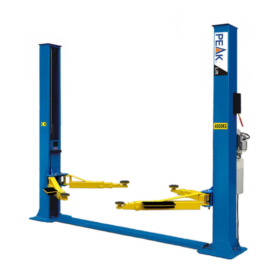
CONTENTS Introduction……………………………………............2 Specification and technical……………………………………………………………………..4 Installation requirement..............6 Step of Installation .................7 Explosive view................20 Test run……………................27 Operation instruction................29 Maintenance..................29 Trouble shooting……………………………………………………………………………………………30... - Page 3 I. PRODUCT FEATURES AND SPECIFICATIONS FLOORPLATE CHAIN-DRIVE TWO POST LIFT Model 209X BP10000X (See Fig. 1) · Dual hydraulic cylinders, designed and made as standards, utilizing oil seal in cylinder · Self- lubricating UHMW Polyethylene sliders and bronze bush · Floor-plate design, provide unobstructed floor space ·...
- Page 4 For Model 209X BP10000X Fig. 2...
-
Page 5: Installation Requirement
II. INSTALLATION REQUIREMENT A. TOOLS REQUIRED Rotary Hammer Drill (Φ19) Carpenter’s Chalk Hammer Screw Sets Level Bar Tape Measure (7.5m) English Spanner (12") Pliers Ratchet Spanner With Socket (28 Socket Head Wrench (6 ... -
Page 6: Step Of Installation
B. SPECIFICATIONS OF CONCRETE (See Fig. 4). Specifications of concrete must be adhered to the specification as following. Failure to do so may result in lift and/or vehicle falling. 1. Concrete must be thickness 100mm minimum and without reinforcing steel bars, and must be dried completely before the installation. - Page 7 C. Check the parts before assembly. 1. Packaged lift and hydraulic power unit ( See Fig. 6). Fig. 6 2. Move the lift aside with fork lift or hoist, and open the outer packing carefully, take off the parts from upper and inside the column, take out the parts box, check the parts according to the shipment parts list (See Fig.
- Page 8 5. Open the carton of parts and check the parts according to parts box list (See Fig. 10). Model 209X Fig. 10 D. Position powerside columns Lay down two columns on the installation site parallelly, position the powerside column according to the actual installation site. Usually, it is suggested to install powerside column on the front-right side from which vehicles are driven to the lift (See Fig.
- Page 9 E. Connecting the cables 1. Put down columns and then push the carriages higher than chain pulley (See Fig. 12). B. Push the carriages higher than chain pulley, cable pass through from the top of the carriages to the hole of the bottom steel plate of the carriages C.
- Page 10 F. Position columns (See Fig. 14) Check the columns plumbness with level bar, and adjusting with the shims if the columns are not vertical. 2850 mm 209X Check the columns plumbness with level bar from front and side Fig. 14...
- Page 11 G. Fix anchor bolts 1. Prepare anchor bolts (See Fig. 16) Washer Lock washer Fig.16 2. Using the prescribed rotary hammer drill, and drill all the anchor holes and install the anchor bolts. Then tighten the anchor bolts (See Fig. 17). Note: Torque of Anchors is 150N.m .Minimum embedment of Anchors is 90mm.
- Page 12 H. Lift the carriages up by hand and make them be locked at the same level (See Fig. 18). Fig. 18...
- Page 13 I. Install cable (See Fig. 18) The fitting of cable pass through the hole of the carriages and be screwed with two cable nuts. Fig. 18...
- Page 14 J. Assembly oil hose assy. (See Fig. 19). Fig. 20...
- Page 15 K. Install hydraulic power unit and oil hose assy. (See Fig. 20). ratchet spanner to Using 19# Lock the nut Fix the oil hose by retainer. Fig. 20...
- Page 16 L. Install safety device and safety cable (See Fig. 21). 1. Assemble safety cable from offside safety assy. NOTE: 2. Pay attention to the connecting direction of safety cable. Safety cable connecting View A direction View B Fig. 21...
- Page 17 M. Assemble floor cover (See Fig. 22). Floor Cover Fig. 22 N. Install lifting arms and adjust the arm locks 1. Install the lifting arms (See Fig. 23, 24) Spanner loose screw Snap Ring Use the 8 socket head Fig. 23 wrench to loosen the socket bolt Fig.
- Page 18 2. Lowing the socket head wrench carriages down to the lowest position, then use the to loosen the socket bolt (See Fig. 24) 3. Adjust the moon gear as arrow direction (See Fig. 25). 4. Adjust the moon gear and arm lock to make it to be meshed, then tighten bolts of arm lock (See Fig.
- Page 19 4. Terminal 4# of control button is connected with terminals A1of AC contactor; Terminal 3# of control button is connected with terminals L1of AC contactor. Single phase Fig. 27 Three phase motor 1. Circuit diagram (See Fig. 28) Three phase Fig.
- Page 20 2. Connection step (See Fig. 29) a. The source wires L1, L2, L3 are connected with terminals of AC contactor marked L1, L2, L3 respectively. b. Terminal of AC contactor marked L1 is connected with terminals 4# of control button. Terminal A1 of AC contactor is connected with terminals 3# of control button.
- Page 21 IV. EXPLODED VIEW Model 209X BP10000X Car-in direction Fig. 30...
- Page 22 Part list BP1000 209X Part no Name 11203140 Power side column assy 11203141 10209011 Safe release pulley Clip spring 10209010 10209008 Safe release cover 10209009 Hex bolt 10206006 Washer 10206023A Hex nut 81513001/8151300 Power unit 11206002 Safe block pin 10209007...
- Page 23 10206045 Rubber protective strip 10203501B Part box 10203502A Part box 11206046 Rack handle(right) 10203156 Lifting arm ass 10209153 Rack handle ring 10206032 Axle spring 10620065 Leveling adjusting pad 10201090 Leveling adjusting pad 11206049 Alignment gear 10209033 washer 10209034 Elastic medium 10206048 Hex nut 11217168...
- Page 24 Lifting arm(10203156) Fig 47 Part no Name Part no Name 10206048 Inner hex nut 10209034 washer 10209039 washer 10209033 washer 10209022 washer 11201049A Inner arm assy 11206049 Alignment gear 10420138 Inner hex nut 11203146 Outer arm assy 10209134 Rubber pad stand 11203147 Middle arm assy 11680030C...
- Page 25 Parts of cylinder Part no Name Part no Name Piston rod adjusting 25-1 11201027 Piston rod 25-8 11201037 sleeve 25-2 11201028 Piston 25-9 10209078 Dusty wing 25-3 10206069 O ring 25-10 10201032 O ing 25-4 10201029 Wearing ring 25-11 11201033 End cover 25-5 10201030...
- Page 26 Plastic ball with rack 81400292 Gear pump 10209020 handle 81400537 Trimmer valve 81400125 Release valve nut 10209034 Washer 81400124 Relief valve gasket 81400295 Hex nut 81400449 Gasket(short) 81400365 O ring 81400492 Release valve 10209152 belt 81400267 Check valve 85090167 magnet 81400288 Oil suction hose 81400290...
- Page 27 220v/60hz/manual Fig 34 Power unit of 220V/60HZ/manual part list Part no Name Part no Name 81400180 Rubber pad 10420070 Button switch 81400130 Starting capacitance 41030055 AC contractor 420148 Cross round nut 81400287 Motor connecting box Label of amgo power 81400066 Capacitance cover 71111065 unit...
-
Page 28: Test Run
Illustration of hydraulic valve for hydraulic power unit Protective ring Oil return port Relief valve Release valve Throttle Check valve valve Oil outlet Handle for relief valve Fig. 35 V. TEST RUN 1. Adjust synchronous cable (See Fig. 35) Push button “UP” to lift the carriages up to the position of the cable nut higher than chain pulley. - Page 29 3. Adjust the lower speed You can adjust the lower speed of the lift if needing: Loosen the Fixing Nut of the throttle valve, and then turn the throttle valve clockwise to decrease the lower speed, or counterclockwise to increase the lower speed. Do not forget to tighten the fixing nut after the lower speed adjustment has been done.
-
Page 30: Operation Instruction
VI. OPERATION INSTRUCTIONS Please read the safety tips carefully before operating the lift To lift vehicle 1. Keep clean of site near the lift; 2. Position lift arms to the lowest position; 3. To shortest lift arms; 4. Open lift arms; 5. -
Page 31: Trouble Shooting
Every six months: 1. Make a visual inspection of all moving parts for possible wear, interference or damage. 2. Check and adjust as necessary, equalizer tension of the cables to insure level lifting. 3. Check columns for plumbness. 4. Check Rubber Pads and replace as necessary. 5. - Page 32 72120307 01/2019...
Need help?
Do you have a question about the 209X and is the answer not in the manual?
Questions and answers