Table of Contents
Advertisement
Advertisement
Table of Contents

Subscribe to Our Youtube Channel
Related Manuals for Peak 409


Summary of Contents for Peak 409
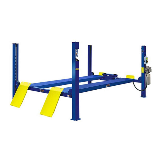
- Page 1 Original FOUR-POST LIFT Model:409/410/412/ 409A/410A/412A /412AX...
- Page 2 CONTENTS Product Features and Specifications ............. 1 Installation Requirement ..............2 Steps of Installation ................4 Exploded View ................. 33 Test Run ..................44 Operation Instruction ............... 47 Maintenance ................... 48 Trouble Shooting ................49 Scarping of Equipment ..............49...
- Page 3 I. PRODUCT FEATURES AND SPECIFICATIONS 4-POST MODEL 409(A440) FEATURES · Electric control operation system. · Mechanical self-lock and air-drived safety release. · Electrical hydraulic power system, cable-drived. · Non-skid diamond platforms. · Adjustable platform and adjustable safety lock ladders. ·...
- Page 4 II. INSTALLATION REQUIREMENT A. TOOLS REQUIRED Rotary Hammer Drill (Φ19) Carpenter’s Chalk Hammer Screw Sets Level Bar Tape Measure (7.5m) English Spanner (12") Pliers Ratchet Spanner With Socket (28 Socket Head Wrench (3 ...
- Page 5 B. Equipment storage and installation requirements. The equipment should be stored or installed in a shady, normal temperature, ventilated and dry place. C. SPECIFICATIONS OF CONCRETE (See Fig. 4) Specifications of concrete must be adhered to the specification as following. Failure to do so may result in lift and/or vehicle falling.
- Page 6 III. STEPS OF INSTALLATION A. Location of installation Check and insure the installation location (concrete, layout, space size etc.) is suitable for lift installation. B. Check the parts before assembly The equipment should be unload and transfer by forklift. Fig.5 2.
- Page 7 5. Loose the screws of the upper package stand, take off the offside platform, take out the parts inside the power-side platform, than remove the package stand. 6. Move aside the parts and check the parts according to the shipment parts list (See Fig. 9 and fig10). 6.1 Model 409/410/412 Fig.9 6.2 Model 409A/410A/412A/412AX Fig.10...
- Page 8 7. Open the carton of parts and check the parts according to the parts box list (See Fig. 11 and 12) 7.1 Model 409/410/412 Fig. 11 7.2 Model 409A/410A/412A/412AX Fig. 12...
- Page 9 8. Check the parts of the parts bag according to the parts bag list (See Fig. 13 and 14) 8.1 Model 409/410/412 Fig. 13 8.2 Model 409A/410A/412A/412AX Fig. 14...
- Page 10 Make sure the size is right and base is flat (see Fig. 15). Note: Reserve space front and behind the installation site. Car in Direction Use a carpenter’s chalk line to establish installation layout Fig. 15 409, 409A 4600mm 3208mm 5608mm 410, 410A 4998mm 3356mm...
- Page 11 E. Fix the anchor bolts 1. Prepare the anchor bolts (See Fig. 17). Spring washer Washer Fig. 17 2. Using the prescribed rotary hammer drill, and drill all the anchor holes and install the anchor bolts. Do not tighten the anchor bolts (See Fig.
- Page 12 2. Install safety ladders (See Fig. 20). This height should be the same for four safety ladders Safety ladder pass through the hole of the top plate, then tighten the two nuts Fig. G. Put the cross beams at the same height (See Fig.
- Page 13 Install power-side platform. Put the power-side platform upon the cross beams by fork lift or manual, offset the cross beams to the outside till the pulleys of both platforms can set up into the cross beams . Install the power-side platform and screw up the bolts ( (See Fig.22 23) Fig 24 Offset the cross beam lean...
- Page 14 Assembly offside platform and slider block, check the plumbness of columns with level, adjusting with the shims if not, and then tighten the anchor bolts (See Fig. 25 26). Offside platform Power-side platform 3-15 Using the Ratchet Spanner 3-16 With Socket to tighten the bolts 3-14 Install the slider block on...
- Page 15 1. Pass through the cables from the platform to the columns according to the number of the cables (See Fig. 27). Fig. 27 ④ Model 409/409A Length 3250mm 9250mm 4850mm 7654mm (inc. connecting fitting) 410/410A Length 3725mm 10125mm...
- Page 16 2. The cable pass through the cross beam to top plate of columns and be screwed with cable nuts.( ) Installation for Cable limit Pin on cross beam See fig 28, 29 (See Fig. 24). Cable pass through top plate Cable pass through between the and be screwed with cable nuts.
- Page 17 Illustration for platform cables (See Fig. 31 & 32 & 33). Cable ④ Cable ② Cable ② Cable ④ Cable ③ Cable ① Fig. 31 Cable ④ Cable ④ Cable ③ Cable ② Cable ② Cable ① Fig. 32 Cable ② Cable ④...
- Page 18 K. Install oil-water separator, solenoid air valve, control box and power unit. 1.For electric control air-operated four post lift (See Fig. 34 & 35). 24 25 26 27 28 Air inlet Air outlet Oil-water separator air flow direction Oil-water separator and Air Solenoid Valve Fig.
- Page 19 L. Install hydraulic system (See Fig. 36). Note: Oil hoses and oil return pipe connected to oil cylinder must be passed above the cable and cylinder inlet port must swing upward to avoid the oil hose and Oil Hose & Air lines pass through...
- Page 20 M. Install air-line system 1. Connecting front and rear Cross Beam cylinders by using 6*4 black air pipe. (the actual length of air line can be cut by user) See Fig.40 2, Cut the 6*4 black air pipe by scissor between two retainers, then connect the air line with T fitting.
- Page 21 4. Connecting Oil-water separator and Air solenoid valve using air line (See Fig. 43) Connecting Oil-water separator and Air solenoid valve using black air line ¢8×¢6×180mm Oil-water separator solenoid valve air line ¢6×¢4 Fig. 5. Connecting air inlet (Air supply pressure 5kg/cm - 8kg/cm ), adjusting the air pressure of Oil-water separator to...
- Page 22 N. Install electrical system 1. Install high limit switch (See Fig. 45) Connecting 11 & 12 (NC) of limit switch to terminals 3 & 5 control box High limit swit ○ wire Fig. 45 2. Install lower alarm limit switch (See Fig.
- Page 23 3. Connecting wire of limit switch on cross beam to control box (See Fig. 47) Male Terminal block Male Terminal block Female Terminal block Male Terminal block ○ 1 Take out Support Terminal block A/B Support Terminal block for wire ○...
- Page 24 4. Connecting wire with control box (See Fig. 48) Note: 1)Specification of wire for limit switch and air solenoid valve are 2*1mm . The wire of power source for 3 phase is 5*2.5mm , for single phase is 3*4mm (The user should prepare by yourself) 2) Using white bobbin to wind around wire and air line.
- Page 25 5. 380V Wire connection and circuit diagram 5.1 Wire connection diagram in the control box (See Fig.49) Power High Wire of Wire Wire Lower limit wire hydraulic ○ ○ switch limit solenoid solenoid motor wire valve ○ switch valve limit wire wire switc...
- Page 26 .3 380V Circuit diagram (See Fig.51) 3 Phase Fig. 51 Circuit component Item Name Code Specification Item Name Code Specification Power switch 380V AC Push button Duplex Breaker Down Triplex Push button Breaker Pass Duplex Breaker Push button Lock Single AC contactor 24V AC Motor...
- Page 27 6. 220V Wire connection and circuit diagram 6.1 Wire Connection diagram in the control box (See Fig. 52) Power High Wire of Wire Wire Lower limit wire hydraulic ○ ○ switch limit solenoid solenoid motor wire valve switch ○ valve limit wire switc...
- Page 28 6.3 220V Circuit diagram (See Fig. 55) 3 Phase Single Phase Fig. Circuit component Item Name Code Specification Item Name Code Specification Power switch 380V AC Push button Duplex Breaker Down Triplex Push button Push button Breaker PASS Duplex Breaker Push button LOCK Single AC contactor...
- Page 29 O. Install spring and safety cover of cross beam (See Fig. 55 Fig. P. Install drive-in ramp, tire stop plate, platform lock plates, steel ball set (See Fig. 56, 57 Install Drive-in ramp Install Tire stop plate Fig. 56 Fig. 57...
- Page 30 Q: Illustration of installing the optional air line kits 1. Install air line kit a. Connect the air line fittings with 8*6 black air line (The length of air line can be cut accordingly) (Fig.58) View a View b Fig.
- Page 31 201-5 201-8 201-11 Air Pump 201-10 201-9 201-5 Connect the elastic Air line to the male View c connector of the Rolling Jack Air Pump View d c.Tighten the oil hose of air line kit, d. Another side of the air line which shown in view d connect to the oil hose and the air line of the lift air line system by tie kits and pass...
- Page 32 b. Connecting air solenoid valve (Fig.59). Replaced with T fitting. Fig. 201-12 201-5 line connect with air cylinder 2.Connecting air source, and operate the Jack with air pump. Parts For Air line kits(optional) Item Code Description 201-1 1061K090 Fast female connector 201-2 1061K091 Air hose connector...
- Page 33 R. Optional extension Kit Installation. 1. Lift the equipment to about 1400mm from ground, lock it to the safety ladder, remove the cable limit bolts and platform fixing bolts Fig 60 Then remove the platform fixing bolts Remove the cable limit bolts first Fig 60 2.
- Page 34 View for optional kits with View for optional kits with Turnplate cover Turnplate only. Turnplate cover Turnplate Fig 63 Fig 62 Item Part Description Part Description Textured 11420711 Cover Turnplate Block 1040905 (for 409A/410A/412A/412AX) Adjusting 11480033 Block 1 set Available for 409A,410A 1140903 Extension Kit (2pcs) 1 set...
- Page 35 IV. EXPLODED VIEW 409/410/412 Fig.64...
- Page 36 409A/410A/412A/412AX Optional Turnplate (need 35mm height adjusting block 1pc both side) Fig.65...
- Page 37 Item Part No. Description 409A 410A 412A 412AX 11420011A Power side column 11420002 Off side column 10420252 Cross Beam Assy 10480039 10420239 Limit Slide Block 10209059 Anchor Bolt 3/4*5-1/2 11410022 Safety Ladder 10420175A Hex Nut M20 11420218 11430003 11490001 Power side platform 11496001 11440038 11440002A...
- Page 38 Item Part No. Description 409A 410A 412A 412AX 10420251 Cross beam limit switch assy. 11420010A Fixing plate for limit switch 10420225 Top limit switch assy. 11420203 Fixing Plate for Limit Switch 11420204 Wire protective cover 10420156 Protective Ring φ24 11420004 Pin for drive-in ramp 10420005 Socket set screw M5*8...
- Page 39 10420245 Straight Fitting 10209119 Compensation Valve 10420247 10201020 Fitting 10420246 Oil Hose 2065mm 10490007 Oil Hose 2450mm 10440042 Oil Hose 2550mm 10420120 Extended Straight Fitting (with Nut) 10207026 Oil Hose L=1520mm 10209060 Fitting for Power Unit 10420095 Straight Fitting 10420124 T-Fitting For Air Line 10420242 T Fitting...
- Page 40 Fig. Qty. Item Part# Description 409(A) 412(A) 410(A) 412AX 57-1 10420059 Dust Ring 57-2 10420060 Y- Ring 11410082 57-3 Head Cap 11420061 10410083 57-4 O- Ring 10420062 11410084 57-5 Bore Weldment 11420063 57-6 11420064 Piston Rod 11410085 57-7 11420065 10410086...
- Page 41 Fig. 67 Item Part# Description Qty. 10420252 Cross Beam Assy. (409/409A/412/412A) 10480039 Cross Beam Assy. (410/410A/412AX) 10420051B Plastic cover for Crossbeam 10209009 Cup Head Bolt M6*8 11420044 Limit Slider Block 10420138 Socket Bolt M6*16 11420038 φ16 Pin 10420037 φ16 Snap Ping...
- Page 42 104200126 3 Phase 10420281 Single Phase Fig. 68 Item Part# Description Qty. 33-1 10420069A Cover Of Control Box 33-2 10420071 Button UP 33-3 10420070 Button Lock 33-4 10420072 Button Down 33-5 10420139 Screw 33-6 10420074 Power Switch (QSI) 33-7 10420075A Terminal Group 33-8 10420133A...
- Page 43 4.4 Power unit (81523001/81523002) 220V/50HZ/1 Phase 380V/50HZ/3 Phase Fig. 69...
- Page 44 Parts For Electric Power Unit 220V/50Hz/1 Phase Item Part No. Description QTY. Note 81400180 Rubber Pad 81400130 Star Capacitor 81400088 Run Capacitor 10420148 Cup Head Bolt with washer 81400066 Cover for capacitor 81400363 Motor connect sharft 81400362 Valve Body 10209149 Lock washer φ6 81400276 Iron Plug...
- Page 45 Parts For Electric Power Unit 380V/50Hz/3 Phase AMGO Label 71150055 AMGO Label 71150055 Cup Head Bolt 81400300 Motor Connecting Shaft 81400363 81400362 Manifold Block 10209149 Spring Washer Inner Hex Iron Plug 81400276 Red Plastic Plug 81400259 Socket Bolt 85090142 81400292 Gear Pump Spring Washer 10209034...
- Page 46 Illustration of hydraulic valve for power unit Oil return port Relief valve Solenoid Oil Outlet valve Check valve Throttle valve Fig. 70 V. TEST RUN: 1. Fill the reservoir with approximately 11L Hydraulic Oil (Note: In consideration of Power Unit’s durability,please use Hydraulic Oil 46#). Press button , the Cables will be strained.
- Page 47 6.1 Press button , the Cables will be strained. Check whether the distance between lever of Limit Switch on Cross Beam and the Slack-cable safety lock is 5mm. If not, please adjust the distance correctly (See Fig. 71) 6.2 Press self-lock button, the Cross-beam will be locked to the safety ladders, and the cables are released, Check whether lever of Limit Switch on Cross Beam touch the Slack-cable safety lock and whether Limit Switch is open completely.
- Page 48 Circuit Diagram of Hydraulic System 1. Filter 2. Gear pump 3. Cylinder 4. Relief Valve 5. Motor 6. Throttle Valve Release Valve 8. T fitting 9. Check valve 10. Cylinder For J6 Fig. 61 Remark: The T fitting No. 8 is specially for the optional power unit drive rolling Jack model J6E only.
- Page 49 VI. OPERATION INSTRUCTIONS To lift vehicle 1. Keep clean of environment near the lift; 2. Drive vehicle to the Platform and put on the brake; 3. Turn on the power and press the button UP , raise the lift to the working position; Note: make sure the vehicle is steady when the lift is raised.
- Page 50 VII. MAINTENANCE SCHEDULE Monthly: 1. Re-torque the anchor bolts to 150Nm; 2. Lubricate cable with lubricant; 3. Check all cable connection, bolts and pins to insure proper mounting; 4. Make a visual inspection of all hydraulic hoses/lines for possible wear or leakage; 5.
- Page 51 VIII. TROUBLE SHOOTING TROUBLE CAUSE REMEDY 1. Button does not work 1.Replace button 2.Wiring connections are not in good condition 2.Repair all wiring connections Motor does 3. Motor burned out 3.Repair or replace motor not run 4. AC contactor burned out 4.Replace AC contactor 5.
- Page 52 PEAK CORPORATION No. 3 Luomu Road,Shishan Town,Nanhai District,Foshan(528225),Guangdong,China Tel:86-757-81102815 81102805 Fax: 86-757-81102809 Email:peak@peaklift.cn http://www.peaklift.cn Manual Part No.: 72114208 Revision Date: 2019/12...
Need help?
Do you have a question about the 409 and is the answer not in the manual?
Questions and answers