Table of Contents
Advertisement
Advertisement
Table of Contents

Related Manuals for Peak MC-600H


Summary of Contents for Peak MC-600H
- Page 1 Motorcycle lift MC-600H...
-
Page 2: Table Of Contents
CONTENTS I. Product Features and Specifications…………………....…….2 II. Installation requirement...…………………………....……..…3 III. Steps of Installation...…………………………....…………..…4 IV. Exploded View………………………………………….....….…..9 V. Test Run…….……………………………………..…….…......12 VI. Operation Instruction.…………………………....…..…….…...13 VII. Maintenance……………………………………....….………..14 VIII. Trouble shooting.……………………………….…....……….…15 IX. MC-600H parts list……..…………….………........….16... -
Page 3: Product Features And Specifications
I .PRODUCT FEATURES AND SPECIFICATIONS Motorcycle lift MC-600H: ● Hydraulic direct-drive cylinders, designed and made on ANSI standard, utilizing oil seal in cylinder Self-lubricating UHMW Polyethylene sliders and bronze bush ● Non-skid diamond platforms ● Automatic safety release system ●... -
Page 4: Installation Requirement
II . INSTALLATION REQUIREMENT A. TOOLS REQUIRED Rotary Hammer Drill (Φ19) Ratchet Spanner with Socket # :(28 Screw Grease gun English Spanner (12") Hook Spanner (40~42mm) Pliers Wrench Set # # # # ... -
Page 5: Steps Of Installation
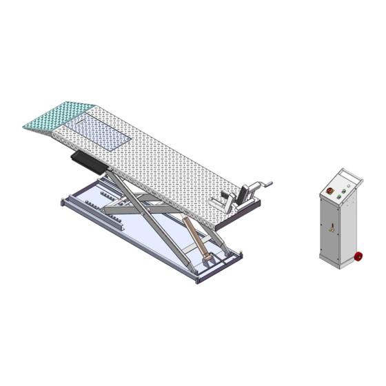
B. SPECIFICATIONS OF CONCRETE Specifications of concrete must be adhere to the specifications as following. Failure to do so may result in lift and/or vehicle falling. 1. Concrete must be thickness 100mm minimum and without reinforcing steel bars, and must be dried completely before lift installation. 2. - Page 6 2. Open the parts box, check the parts according to the parts list (See Fig. 4). Fig.4 3. Open the parts bag, check the parts according to the parts list (See Fig. 5). Fig.5 B. Put the lift and control cabinet in good order and connect the oil hose, see Fig.6 51-1 51-2...
- Page 7 C. Install Electrical System 1. Connect the wire according to below diagram. ( Fig.7 ) Ground wire Power Motor wire wire Fig.7 2.2 Schematic circuit diagram(Fig.8) Switch button SB(UP) Fig.8 D. Fastening all the oil hose fittings, fill the power unit with right amount hydraulic oil ( in order to ensure the working life of hydraulic system and the machine reach the best performance, please fill in the no.46 high quality anti-wear hydraulic oil.
- Page 8 1 After connecting the wire, lift the motorcycle lift to a suitable height, install the adjustable fixing device according to below photo; 2 The adjustable fixing device can be chosen to install in different installed position of the platform. Fig.9 F.
-
Page 9: Exploded View
Fig.10 G. Install platform extension kit(optional).See Fig 11 Note: Connect the holes on platform extension kit and the platform. Install the adjustable fixing device on the platform extension kit. Fig.11 IV. EXPLODED VIEW... - Page 10 MODEL:MC-600H Fig.12...
- Page 11 Control Cabinet 油 Fig.13 Cylinder Fig.14...
- Page 12 Power unit PEAK ELECTRIC POWER UNIT PEAK ELECTRIC POWER UNIT 110V/60Hz/1 phase 220V/60Hz/1 phase Fig.15 Fig.16 Illustration of hydraulic valve for PEAK electric power unit(220V/60Hz/1 phase) Protective ring Release valve Release valve Oil return port Handle Throttle Release valve valve...
-
Page 13: Test Run
V. TEST RUN 1. Install anchor bolts. see Fig.18 Install the anchor bolts to fix the machine after installing. Fig.18 Steps: Note: Twisting force is 150N.m for fixing the anchor screw , knock the anchor bolt into the ground at least 90mm. Drilling Tighten Bolting... -
Page 14: Operation Instruction
VI. OPERATION INSTRUCTIONS 1. Install well the oil hose between cylinder and power unit, connect well the wire, the motorcycle lift can be used. 2. Raise up the lift without vehicle for testing. 3. To lift vehicle Lower the lift to the lowest position, loosen the adjustable fixing device. Move the motorcycle to the platform, put the wheel in the adjustable fixing device, set well the motorcycle. -
Page 15: Maintenance
VII. MAINTENANCE SCHEDULE Monthly maintenance: 1. Lubricate all moving parts with lubricant. Fig.24 Fig.24 2. Check all connectors, bolts and pins to insure proper mounting. 3. Make a visual inspection of all hydraulic hoses/lines for possible wear or leakage Every six months: 1. -
Page 16: Trouble Shooting
VIII.TROUBLE SHOOTING TROUBLE CAUSE REMEDY 1. Button does not work 1. Replace button 2. Wiring connections are not 2. Repair all wiring connections in good condition Motor does not run 3. Motor burned out 3. Repair or replace motor 4. AC contactor burned out 4. -
Page 17: Mc-600H Parts List
IX. PARTS LIST Note Item Part# Description QTY. 720020 Platform 720021 Cover plate of Platform 217069 Hex bolt 720022 Drive-in ramp 720023 Outer scissor assy. 720024 Inner scissor assy. 610023 Sliding block 720109 Pin for safety device 206019 Snap ring 720061 Socket bolts 720026... - Page 18 Note Item Part# Description QTY. 209019 Socket bolt 720048 Tire stop tube assy. 720045 Washer 209033 Washer 209034 Lock washer 420043 Socket bolt 720017 Adjusted shaft 720016 Connecting plate for handle 206023 Self locking nut 720015 Fixed Bolt for operating handle 720018 Operating handle 206006...
- Page 19 Parts for cylinder Note Item Part# Description QTY. 20-1 640030A Bore Weldment 20-2 640031A Piston Rod 20-3 201034 Bleeding Plug 20-4 201033 Head Cup 20-5 209078 Dust Ring 20-6 201032 0-Ring 20-7 201035 0-Ring 20-8 201028 piston 20-9 206069 0-Ring 20-10 201031 0-Ring...
- Page 20 Parts for PEAK electric power unit, 220V/60Hz/1 phase Note Item Part# Description QTY. 81400242 Motor 200-1 81400219 Protective ring 200-2 81400220 Run capacitor 200-3 81400221 Motor connecting shaft 200-4 81400243 Valve body 200-5 81400223 Relief valve 200-6 81400231 Tighten nut of Throttle valve...
- Page 21 Parts for PEAK electric power unit, 110V/60Hz/1 phase Note Item Part# Description QTY. 200A-1 81400247 Motor 200A-2 81400219 Protective ring 200A-3 81400220 Run Capacitor 200A-4 81400221 Motor connecting shaft 200A-5 81400243 Valve body 200A-6 81400223 Relief valve 200A-7 81400231 Tighten nut of Throttle valve...
- Page 22 No. Of service manual: 72272104 Revised date:2016/12...
Need help?
Do you have a question about the MC-600H and is the answer not in the manual?
Questions and answers