
Subscribe to Our Youtube Channel
Related Manuals for Cumberland G54CBF16GA


Summary of Contents for Cumberland G54CBF16GA
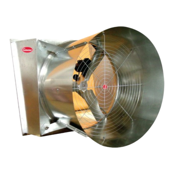
- Page 1 54" Galvanized Butterfly Fan Model: G54CBF16GA Installation and Operation Manual PNEG-1502 Date: 05-08-14 PNEG-1502...
- Page 2 Before beginning installation, check the condition of the fan. Remove the overwrap and packing materials and examine all parts and components for shipping damage. Any damage incurred must be reported immediately to the freight carrier. Model : G54CBF16GA Size 54" Galvanized Housing and Cone Voltage...
-
Page 3: Table Of Contents
Table of Contents Contents Chapter 1 Safety ..............................4 Safety Guidelines ...........................4 Safety Instructions ..........................5 General Safety Information ........................7 Chapter 2 Decals ..............................9 Chapter 3 Installation ............................10 Framing and Positioning ........................10 Installation of the Fan on a Vertical Plane ....................11 Tabbed Cone Panel Assembly ......................12 Butterfly Assembly ..........................14 Grill Guard Assembly ...........................15 Inlet Grill Assembly ..........................16... -
Page 4: Chapter 1 Safety
1. Safety Safety Guidelines This manual contains information that is important for you, the owner/operator, to know and understand. This information relates to protecting personal safety and preventing equipment problems. It is the responsibility of the owner/operator to inform anyone operating or working in the area of this equipment of these safety guidelines. -
Page 5: Safety Instructions
1. Safety Safety Instructions Our foremost concern is your safety and the safety of others associated with this equipment. We want to keep you as a customer. This manual is to help you understand safe operating procedures and some problems that may be encountered by the operator and other personnel. As owner and/or operator, it is your responsibility to know what requirements, hazards, and precautions exist, and to inform all personnel associated with the equipment or in the area. - Page 6 1. Safety Prepare for Emergencies Be prepared if fire starts. Keep a first aid kit and fire extinguisher handy. Keep emergency numbers for doctors, ambulance service, hospital, and fire department near your telephone. Keep Emergency Equipment Quickly Accessible Wear Protective Clothing Wear close-fitting clothing and safety equipment appropriate Eye Protection to the job.
-
Page 7: General Safety Information
In the installation and use of the Butterfly Fan, only genuine Cumberland parts are to be used. Use of other non-genuine parts is a misuse and may lead to dangerous situations. - Page 8 1. Safety Electrical Safety Provisions for an adequate and safe power supply to the fan unit is essential to your safety. Cumberland recommends that a competent and qualified electrician undertake all electrical wiring. All wiring is to be installed in accordance with National, State and Local electrical codes. Fans used to ventilate livestock buildings and other rooms where continuous air movement is essential should be connected to individual electrical circuits with a minimum of two (2) circuits per room.
-
Page 9: Chapter 2 Decals
2. Decals WARNING DANGER DANGER WARNING STAY CLEAR OF ROTATING BLADE SHEAR POINT Blade may start automatically. May cause serious injury. Keep hands clear of moving Disconnect and lockout power sources before servicing. parts. Do not operate with guard removed. Disconnect WARNING HIGH VOLTAGE and lockout power before... -
Page 10: Chapter 3 Installation
3. Installation Framing and Positioning 1. Construct the opening frame to the correct size (61-1/4" H x 58" W) as shown in Figure Remember, framing must be able to support the weight of the fan assembly. Ensure the load bearing portion of the bottom sill is rigid and properly supported. 2. -
Page 11: Installation Of The Fan On A Vertical Plane
3. Installation Installation of the Fan on a Vertical Plane Lifting Hazard. Single person lift could cause injury. Use two (2) or more people or a mechanical lifting device to lift/move heavy equipment. CAUTION 1. Position the fan in front of the opening from the inside of the building. Using a minimum of two (2) people, lift fan housing into the opening. -
Page 12: Tabbed Cone Panel Assembly
3. Installation Tabbed Cone Panel Assembly Figure 3D Ref # Description Top Panel Side Panel Bottom Panel Drain Hole Large Radius Assembly Steps 1. Lay cone panels on the ground as shown in Figure 2. Slip four (4) cone panels together using tab and slot connections on edges of each panel. (Please note that all tabs must be on the inside of the cone assembly.) 3. - Page 13 3. Installation Nuts on outside of cone assembly. Figure 3E Cone strut angle Figure 3F PNEG-1502 54" Galvanized Butterfly Fan...
-
Page 14: Butterfly Assembly
3. Installation Spring clip (12-0457) Clip wires here Figure 3H Spring Clip Figure 3G Clipped Grill Wires Butterfly Assembly 1. Install the spring clips (12-0457) (2 pieces) as shown in Figure 3H onto the butterfly frame. 2. The V-shaped center bar of the butterfly frame weldment should be positioned vertically, with the bottom lining up with the slots farthest out on the cone and the top lined up with the slots farthest in on the cone. -
Page 15: Grill Guard Assembly
3. Installation Grill Guard Assembly Position grill guard lining up attachment hoops with the holes in the cone panels at all positions. Attach and tighten using the 5/16" x 3/4" bolts and 5/16" whiz nuts. (See Figure 3J.) Picture shown is with flattened side cone. -
Page 16: Inlet Grill Assembly
3. Installation Inlet Grill Assembly 1. Remove the folded inlet grill from the packaging. Unfold all four (4) sides lining them up perpendicular to each other. Using the black wire ties, link the sides together using two (2) ties per corner. (See Figure 3K.) After pulling them tight, clip off excess wire tie. -
Page 17: Motor Mounting Instructions (Single Crated Fans Only)
3. Installation Motor Mounting Instructions (Single Crated Fans Only) SUMMARY: The instructions describe how to properly install the motor on your new 54" Galvanized Butterfly Damper Fan. Upon delivery of your 54" Galvanized Fan, you will notice that the motor has been turned around and bolted into location to decrease the width of pallet and maximize shipping container space. -
Page 18: Chapter 4 Wiring
4. Wiring Electrical Hook-Up As previously mentioned, All wiring should be installed in accordance with National, State and Local electrical codes. A certified electrician should complete this portion of the installation to ensure safety and that the wiring is correct for the application. 1. -
Page 19: Chapter 5 Operation And Maintenance
5. Operation and Maintenance Start-Up and Operation of the Butterfly Fan Disconnect and lock out all power sources before servicing equipment. DANGER 1. With the fan de-energized, rotate the prop by turning the fan pulley, look for clearance between the prop tip and the housing. Replace all guards and check all fasteners to ensure they are tight. When satisfied, energize the fan and make note of direction of rotation. -
Page 20: Chapter 6 Troubleshooting
Do they all three appear even? (NOTE: They can be a little different without any problems.) If they are significantly different contact your Cumberland distributor for more information. 2. Is the noise coming from the bearings? Lubricate per instructions and energize the fan. Did the noise subside? If not, the bearings are probably damaged and in need of replacement. - Page 21 NOTES PNEG-1502 54" Galvanized Butterfly Fan...
-
Page 22: Chapter 7 Parts List And Exploded Diagram
7. Parts List and Exploded Diagram Exploded Diagram PNEG-1502 54" Galvanized Butterfly Fan... - Page 23 7. Parts List and Exploded Diagram Ref # Part # Description 12-0332 54" Galvanized Butterfly Fan Venturi 57" x 60-1/2" 13-0221 Propeller, 54" Galvanized Fan (3 Blade) 15-0131 Motor, 1.5 HP 1.5 S.F. 1 PH, 60 Hz (See Notes on Page 24.) 12-0213 Motor Mount Bracket 54"...
- Page 24 7. Parts List and Exploded Diagram * NOTE: Refer to exploded diagram on Page ** NOTE: For high efficiency and ultra efficiency models, use motor part #: 15-0212. For 3 phase 50 Hz and 60 Hz models, use motor part #: 15-0138. *** NOTE: For high efficiency, use motor pulley part #: 017-1422-9 (AK30).
-
Page 25: Chapter 8 Warranty
3 to 5 years - end-user pays 25% All Fiberglass Propellers Lifetime 5 to 7 years - end-user pays 50% AP and Cumberland Flex-Flo/Pan Feeding System Motors 2 Years 7 to 10 years - end-user pays 75% Feeder System Pan Assemblies... - Page 26 Authorities having jurisdiction should be consulted before installations are made. 1004 E. Illinois St. Assumption, IL 62510-0020 Phone: 1-217-226-4421 Fax: 1-217-226-4420 www.gsiag.com Cumberland is a part of GSI, a worldwide brand of AGCO. Copyright © 2014 by Group Printed in the USA CN-311960...
Need help?
Do you have a question about the G54CBF16GA and is the answer not in the manual?
Questions and answers