
Related Manuals for Weinmann BiLevel-ST VENTImotion WM 24800


Summary of Contents for Weinmann BiLevel-ST VENTImotion WM 24800
- Page 1 Service and Repair Instructions VENTImotion BiLevel-ST Home Ventilation Unit WM 24800 VENTIlogic BiLevel-ST Home Ventilation Unit WM 27000...
-
Page 2: Table Of Contents
Contents Introduction ......3 5.6 Disposal ..... . . 27 6. -
Page 3: Introduction
Remember: devices to Weinmann your customer trusts you and is relying on your abil- ity to do the job, just as you rely on Weinmann. Note The following information can be found in the operating instructions for the devices: •... -
Page 4: Overview
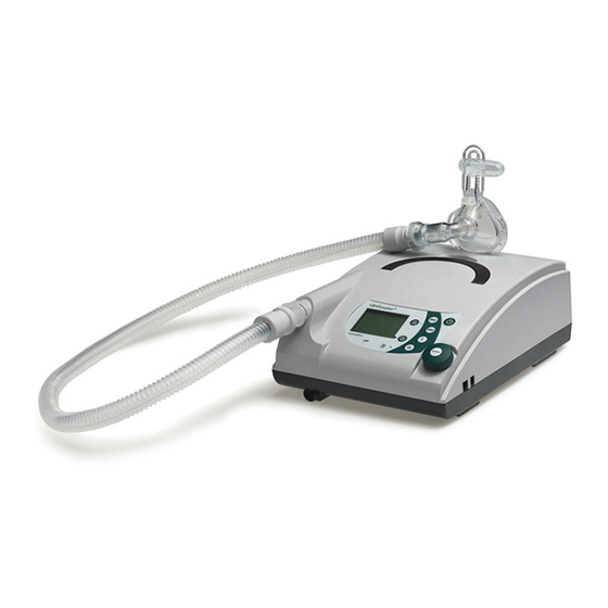
1. Overview VENTImotion/VENTIlogic 1 Bacteria filter 9 Drying adapter 15 Headgear 14 Mask 2 Power supply cable 13 Exhalation 8 Sealing plugs (2x) system 7 Device outlet 3 Handle 12 Hose system 10 Adapter 11 Pressure measurement 4 Serial interfaces hose 5 Control panel and displays 6 Connection for humidifier... - Page 5 1 Bacteria filter To protect the device from contamination, especially if the device is being used by several patients. 2 Power supply cable For connecting the therapy device to the mains power supply. 3 Handle For transporting the device. 4 Serial interfaces For connecting to devices, for display, evaluation.
- Page 6 24 Operating keys For rapid setting by a physician, disabled in patient mode. 25 Menu key For switching to and fro between the standard display and the menu. 26 Humidifier key with LED For switching the humidifier on and off or for setting humidifier stage. Six levels are available.
- Page 7 5 Bar chart for pressure indicator For graphical display of pressure. 6 Ventilation parameters The relevant current ventilation parameters are displayed depending on the active mode. 7 Active ventilation mode The active ventilation mode is displayed at this point in the status line. Symbols used in the display Symbol Significance...
- Page 8 Symbol Significance Respiratory frequency Spontaneously-triggered respiratory phase switch Compulsorily-triggered respiratory phase switch Main window ("Statistics" menu item): Δ Δ Δ Δ p Maximum rise in pressure due to volume compensation Volume Per minute volume Leak System leak (mask, exspiration system, hose system, device) Respiratory frequency Ti/T Proportion of inspiration time in a respiratory cycle...
- Page 9 Menu structure in Physician mode In SX mode: In SXX mode • T • T Target values Actual values Statistics • • • T Means Appliance usage Values to be set: TA statistics TA setting (VENTI logic only) (VENTI logic only) TA mode Mode (VENTI logic...
-
Page 10: Description Of Device
2. Description of device 2.1 Intended use for VENTImotion/VENTIlogic VENTImotion and VENTIlogic are home ventilation • disorders of the respiratory mechanism like devices for the non-invasive, non-life support venti- scoliosis, deformity of the thorax lation of adult patients with respiratory insufficiency •... -
Page 11: Hygiene Treatment
3. Hygiene treatment 3.1 Cleaning and disinfecting in use Caution! This item is described in section “5. Hygienic treatment” of the therapy device operating instructions. There follows a description of the hygiene treatment of the device in the event of repair and in the event of a patient change. -
Page 12: Clean And Disinfect Humidifier During Use
– device outlet, complete, WM 24025 • Insert device outlet WM 24025 – labyrinths WM 24897 • Replacing the WM 24837 control board – decoupling tube WM 24028 This is necessary because the flow sen- Note: – motor frame WM 24898 sor located on the control board cannot be –... -
Page 13: Test The Device
4. Test the device 4.1 General Important! If you find faults or deviations from target values The device must be subjected to the following test fol- during the test, you must not use the therapy device lowing every repair, maintenance and hygienic treat- again until the faults are eliminated. -
Page 14: Connection To Ventisupport
Enter the type, number and date of manufac- ture of the device in the test protocol. 4.5 Test temperature calibration and calibration status Note This test is not needed, as it can only be per- formed on a Weinmann test bench. Test the device... -
Page 15: Test Battery Voltage
4.6 Test battery voltage 1. Plug the red drying adapter into the device out- let of the VENTImotion. 2. Turn on the device. if battery voltage is sufficient, Requirement: maintenance symbol should appear in the dis- play. 3. Replace 4. Turn off the device. Note If battery voltage is inadequate, replace the battery on the control board (see "7.9 Re-... -
Page 16: Test Flow Measurement
6. Read off the pressure displayed by the mea- surement device and enter it on the protocol in the “Measuring result” column. 7. Read off the actual pressure displayed by the therapy device and enter it on the protocol in the “Mask”... -
Page 17: Test Leaktightness
4.10 Test leaktightness 1. Plug the test adapter onto the device outlet. 2. Connect the side connection to the pressure measurement device. 3. Turn on the device. Select CPAP mode in the "Physician" menu and set a pressure of 20 hPa. 4. -
Page 18: Test The Interface With The Venti-O
4.12 Test the interface with the VENTI-O 1. Fit a VENTI-O valve to the therapy device so Indicator that it is ready to work. The indicator on top of the valve housing does not light up. 2. Close the opening of the nasal mask, using your thumb or hand, for example. -
Page 19: Test Noise
4.14 Test noise Note This test is not needed, as it can only be performed on a Weinmann test bench. 4.15 Test all keys, the rotary knob and 115 V mode 1. Plug the red drying adapter into the device outlet. -
Page 20: Test Display Incl. Backlighting And Contrast, The Leds And The Alarm
4.16 Test display incl. backlighting and contrast, the LEDs and the alarm Note Before this test is carried out, the VENTImotion must have been connected to the mains power supply for at least 5 minutes. 1. Switch on the device. A beep sounds. -
Page 21: Test Equipment And Accessories (System Components)
4.17 Test equipment and accessories (system components) • Humidifier VENTIclick present • Hose system present • Oxygen supply valve VENTI-O present • Rechargeable battery VENTIpower present • Medical devices manual present (Germany only) • Operating instructions present Check function of humidifier Important! It is essential to note the heating level set be- fore carrying out this test. -
Page 22: Once Tests Are Complete
Function check VENTI-O 1. Fit the VENTI-O to the therapy device so that Status display it is ready to work. The status display on top of the valve housing does not light up. 2. Attach the test hose supplied (length approx. 48 cm) to the O outlet ( ). -
Page 23: Maintenance
5. Maintenance 5.1 Intervals Both filters must be regularly checked for soiling. • Coarse dust filter needs to be changed ev- ery 6 months. • Fine filter should be changed after no more than 1000 operating hours (filter change sym- appears in the display). -
Page 24: Filter Change
5.2 Filter change Use only original filters made by Weinmann. If third-party filters are used, this will invalidate the warranty and may cause restrictions in terms of function and biocompatibility. Coarse dust filter 1. If the VENTIclick humidifier is connected, first disconnect it from the device. -
Page 25: Reset Filter Change Indicator
Reset filter change indicator 1. To reset the filter change indicator, press menu Patient mode Physician mode with the device switched on and use the dial to select the item in the Pa- Filter change tient menu or in Physician mode, select the menu item and then Device configuration... -
Page 26: Reset Maintenance Symbol
5.4 Reset maintenance symbol After every service/repair performed, the mainte- nance indicator must be set to "0", or the mainte- nance symbol which has appeared in the display deleted. In addition, a new service label (current year +2 years) should be affixed to the rear of the device. -
Page 27: Check The Maintenance Sticker
5.5 Check the maintenance sticker When you have maintained the device, a new maintenance sticker (current year +2 years) must be attached to the rear of the device. • Replace maintenance sticker with one showing the new data (see "8. Spare parts" on page 48). -
Page 28: Malfunctions And Rectification
6. Malfunctions and rectification 6.1 General faults Malfunction Cause Rectification Check connection of power supply cable in device socket. No power supply. Check mains voltage with another device, if necessary (for example a lamp), replace power supply cable if necessary. Mains supply unit defective. -
Page 29: Internal Faults
The ribbon cable of the film Check whether the ribbon cable is correctly connected to the display keypad has slipped out of Device cannot be switched board. the connection. on using the film keypad. Fascia film defective. Replace fascia film (7.12, page 45). 6.2 Internal faults The therapy device performs a self-test of the sen- The therapy device can detect internal faults itself... - Page 30 First line: Second line: Cause Rectification code number 1 at position ... Replace battery on control board (see section 7.9 on page 42). If fault occurs again, replace control board Clock not responding (see section 7.8 on page 39). Replace fan or fan box. (see section 7.7 on battery discharged page 37).
-
Page 31: Repairguide For Ventimotion/Ventilogic
Any handling of the device assumes accurate • If you replace components or individual parts, knowledge and observance of the operatingin- use only original Weinmann parts. structions and the service and repair guide. • When ordering the bottom part of the •... -
Page 32: Close The Device
4. Open the bottom part of the housing away to the side. 5. Undo the connecting cables for the humidifier and the alarm 6. You can now put the bottom part of the housing to one side. 7.3 Close the device Tools and equipment required •... -
Page 33: Replace Mains Supply Unit
7.4 Replace mains supply unit Tools and equipment required • ESD protected work-station • 3 mm Allen key 1. Open the device (see "7.2 Open device" on page 31). 2. Disconnect the power board/mains supply Mains input unit connecting cable from the power connector board (wide connector). -
Page 34: Replace Power Board
7.5 Replace power board Tools and equipment required • ESD protected work-station • 3 mm Allen key 1. Open the device (see "7.2 Open device" on Motor cable page 31). 2. Disconnect the power board/mains supply unit connecting cable from the power board (wide connector). -
Page 35: Replace Box And Filter Holder
14. Insert the rechargeable battery connecting cable into the groove on the power board. Caution! Be absolutely sure that the power board/mains supply unit connecting cable 45 is between the head of the screw and the box as well as in the groove of the power board. - Page 36 7. Dispose of the foam from the expansion space and replace box Replace the complete filter holder 8. If you have not replaced the filter holder, insert a new piece of foam in the expansion space. 9. Connect box and filter holder. To do so, insert the intake-side hose in both parts.
-
Page 37: Replace Fan
7.7 Replace fan Tools and equipment required • ESD protected work-station • 3 mm Allen key 1. Open the device (see "7.2 Open device" on page 31). 2. Remove the power board (see "7.5 Replace power board" on page 34). 3. - Page 38 12. Insert a new lid cushioning insert and box cushioning insert as shown, as well as the two new labyrinths and motor frame Take care with the assembly position. – Insert the labyrinths as shown. – Insert motor frame so that the cutout for the fan cable is flush with the cutout in the box.
-
Page 39: Replace Control Board/Display
7.8 Replace control board/display Perform repair Tools and equipment required • ESD protected work-station • 3 mm Allen key • Phillips screwdriver, size 1 1. Open the device (see "7.2 Open device" on page 31). 2. Remove the power board (see "7.5 Replace power board"... - Page 40 7. Undo the four screws and remove control board 8. Remove spring from the control board and remove battery (see "7.9 Replace battery on control board" on page 42). You need the metal spring for the new control board. If it is unnecessary to replace the display, con- tinue from step 9.
- Page 41 16. Connect the ribbon cable for the fascia film and the display to the control board again: – pull the latch upwards. – push the ribbon cable into the connector. – press the latch back down. Ribbon cable for display Ribbon cable for fascia film 17.
-
Page 42: Replace Battery On Control Board
7.9 Replace battery on control board Tools and equipment required • ESD protected work-station • 3 mm Allen key • Phillips screwdriver, size 1 1. Open the device (see "7.2 Open device" on page 31). 2. Undo the screw on the battery holder and take spring and seal off control board... - Page 43 4. Remove box and filter holder (see "7.6 Re- place box and filter holder" on page 35). 5. Remove the control board (see "7.8 Replace control board/display" on page 39). 6. Pull the pressure-side hose off device outlet Dispose of the pressure-side hose (only when servicing or changing patients).
-
Page 44: Replace Encoder (Dial)
7.11 Replace encoder (dial) Tools and equipment required • ESD protected work-station • 3 mm Allen key • 11 mm Allen key adapter Note If you only want to replace the dialknob, simply pull this off the spindle of the encoder and replace it by a new one. -
Page 45: Replace Fascia Film
7.12 Replace fascia film Tools and equipment required • ESD protected work-station • 3 mm Allen key • Phillips screwdriver, size 1 • Knife with a smooth, flat blade 1. Open the device (see section 7.2 on page 31). 2. Remove the mains supply unit (see section 7.4 on page 33). -
Page 46: Replace Bottom Part Of Housing
7.13 Replace bottom part of housing Tools and equipment required • ESD protected work-station • 3 mm Allen key • Phillips screwdriver, size 1 • Torque wrench 20 – 120 Ncm 1. Open the device (see section 7.2 on page 31). 2. -
Page 47: Replace Top Part Of Housing
7.14 Replace top part of housing Tools and equipment required • ESD protected work-station • 3 mm Allen key • Phillips screwdriver, size 1 1. Open the device (see section 7.2 on page 31). 2. Remove the mains supply unit (see section 7.4 on page 33). -
Page 48: Spare Parts
8. Spare parts 8.1 List of spare parts for VENTImotion/VENTIlogic Note The item numbers in the table are identical to the numbers in the text of this service and repair guide. There are gaps in the numbering because the numbers were assigned in the operating instructions, but not all parts are spare parts. - Page 49 – for 2011 0609 – for 2012 0610 Safety test label * – for 2007 only for internal – for 2008 Weinmann use – for 2009 – for 2010 Hose, intake side WM 24809 Hose, pressure side WM 24852 Bacteria filter, complete...
- Page 50 Item no. Name Article no. Mains input plug WM 24853 Cable securing clip, strain relief WM 24317 Encoder WM 24090 Dial WM 24101 Western socket, 6-pin WM 24508 Western socket, 4-pin WM 24854 Screw WN5412 (for piezo buzzer) WM 50553 Tallow-drop screw KB 30 x 20 WM 22597 Tallow-drop screw KB 30 x 6...
-
Page 51: Spare Parts Required For Servicing
• 1 control board, replacement • 1 "reconditioned" label Important! The removed control board must be returned to Weinmann, otherwise you will be billed the full price! Maintenance kit 5,000 hours or 2 years WM 15684 consisting of: • 1 coarse dust filter •... - Page 52 Maintenance kit 10,000 operating hours or 4 years WM 15679 consisting of: • 1 coarse dust filter • 1 fine filter • 2 silicone hoses, 2.5 x 1.25 SI NF, 200 • 2 silicone hoses 3/7 130 • 1 hose, pressure side •...
-
Page 53: Tools, Test Equipment And Disinfectants
9. Tools, test equipment and disinfectants Below is a list of all the tools and test equipment mentioned in this service and repair guide. The tools and test equipment required in detail can be found in the respective chapter. 9.1 Tools •... -
Page 54: Disinfectants
• Flow measurement device Flow and pressure gauge PF-300 Type EKU VIP ventilator tester to order from: to order from: imtmedical ag EKU Elektronik GmbH Gewerbestrasse 8 Feldstraße 9a CH-9470 Buchs, Switzerland D-56291 Leiningen Phone: +41 81 750 66 99 Phone: +49 6746-1018 Fax: +41 81 750 66 95 Fax: +49 6746-8484... -
Page 55: Technical Data
10. Technical data VENTImotion/VENTIlogic with VENTImotion/VENTIlogic VENTIclick Product class as per EC directive 93/42/EEC Dimensions WxHxD in cm 23 x 12.5 x 34 23 x 12.5 x 45.5 Weight approx. 4.5 kg approx. 4.8 kg Temperature range – operation +5 °C to +35 °C –... - Page 56 VENTImotion/VENTIlogic with VENTImotion/VENTIlogic VENTIclick I:E (Ti/T): Inspiration time 20 % to 67 % of respiratory period Increment Accuracy ±1 % can be adjusted in 6 levels, separately for inspiration and expiration; Trigger level in ST mode, expiration trigger can be switched off Speed of pressure rise adjustable in 6 levels Speed of pressure drop...
-
Page 57: Diagram Of Pneumatic System
800 MHz – 2.5 GHz 0.01 0.12 0.12 0.24 0.37 0.37 0.74 1.17 1.17 2.34 3.69 3.69 7.38 11.67 11.67 23.33 Further technical data are obtainable from the manufacturer, WEINMANN, on request. The right to make design modifications is reserved. Technical data... -
Page 58: Technical Amendments
11. Technical amendments Technical amendment From device no. Date Technical amendments... -
Page 59: Protocols
12. Protocols 12.1 Repair and service protocol Protocols... -
Page 60: Test Protocol
• the alarm generates the correct alarm sound sequence and can be heard without distortion 16.Check of maintenance sticker present • maintenance sticker data updated and applied correctly Maintenance performed: Final test carried out: _______ __________________ date name * test points only feasable with Weinmann test bench Protocols... - Page 64 For decades Weinmann has been developing, producing and marketing medical devices for markets around the world. In cooperation with our partners we design economic health systems for diagnosis and therapy in Sleep Medicine, Home Mechanical Ventilation, Oxygen Medicine and Emergency Medicine.
Need help?
Do you have a question about the BiLevel-ST VENTImotion WM 24800 and is the answer not in the manual?
Questions and answers