Vittorazi Motors Moster 185 Plus Maintenance Manual
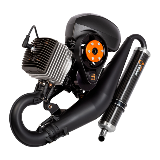
Paramotor engine
Hide thumbs
Also See for Moster 185 Plus:
- User manual (26 pages) ,
- Installation manual (40 pages) ,
- User manual (46 pages)
Table of Contents
Advertisement
Advertisement
Table of Contents

Subscribe to Our Youtube Channel
Related Manuals for Vittorazi Motors Moster 185 Plus


Summary of Contents for Vittorazi Motors Moster 185 Plus
- Page 1 MOSTER 185 Plus Maintenance manual release V1/2022 valid for MY20-MY22 versions...
- Page 2 Moster 185 Plus - Maintenance manual - V1...
-
Page 3: Table Of Contents
3.6 Gaskets 3.7 Exhaust system 3.7.1 Manifold, exhaust bushing disassembly 3.7.2 Manifold, exhaust bushing maintenance 39 3.7.3 Manifold, exhaust bushing assembly 3.7.4 Silencer disassembly 3.7.5 Silencer maintenance 3.7.6 Silencer assembly 3.8 Rubber mountings Moster 185 Plus - Maintenance manual - V1... - Page 4 3.12.3 Bell, clutch disassembly 3.12.4 Transmission maintenance 3.12.5 Bell, clutch assembly 3.12.6 Pulley assembly 3.12.7 Belt insertion 3.12.8 Belt tensioning 3.13 Piston, cylinder, head 3.13.1 Piston, cylinder, head disassembly 3.13.2 Piston, cylinder, head maintenance Moster 185 Plus - Maintenance manual - V1...
- Page 5 3.13.3 Piston, cylinder, head assembly 3.14 Crankcase 3.14.1 Crankcase disassembly 3.14.2 Crankcase maintenance 3.14.3 Crankcase assembly 3.15 Tightening values Moster 185 Plus - Maintenance manual - V1...
-
Page 6: Introduction
The professional manual includes: technical descriptions of the maintenance phase and reference values. All the components of Vittorazi Motors are checked and tested in a process of industrial quality control before the assembling. Then by sampling the complete motors are checked to assure the functionality of all the parts through a complete test of twenty minutes on the bench. - Page 7 Reading tips: Attention, danger, risk Any situation or condition which may result in a serious danger Recommendation, warning, important advice Moster 185 Plus - Maintenance manual - V1...
-
Page 8: Be Careful! Read It Completely
• Vittorazi Motors and its distributors decline any direct or indirect responsibility related to this kind of activity. By using a new engine, the owner agrees that these terms and conditions have been accepted at the time of purchase of the product. - Page 9 The temperature limit of CHT is 250° Celsius. Do not persist above this temperature threshold, engine overheating and irreversible damage could occur. The temperature limit of EGT is 650° Celsius. Do not persist above this temperature threshold, engine overheating and irreversible damage could occur. Moster 185 Plus - Maintenance manual - V1...
-
Page 10: Maintenance
Any procedure of installation, maintenance and/or repair of the products must be carried out exclusively with the original Vittorazi Motors parts and tools specified by Vittorazi, in compliance with the specifications contained in the user, installation and/or maintenance manual of the products;... -
Page 11: Maintenance Schedule
1) or after a year 2) rope, spring, hooks or a new pull starter system 3) springs 4) each time the component is disassembled 5) head, exhaust port, decompressor hole 6) tensioning Moster 185 Plus - Maintenance manual - V1... - Page 12 Carburation from spark plug colour Spark plug Spark plug connector Carburettor Carburettor membranes Airbox Snaplock Airbox Airbox sponge and sleeve Reed valve petals Pull starter system The table follows in the next page Moster 185 Plus - Maintenance manual - V1...
- Page 13 ���� Exhaust manifold with springs Soundproofing material silencer Silencer rubber Gaskets (cylinder, carburettor, reed valve, exhaust, silencer) Piston Piston roller bearing Head and cylinder The table follows in the next page Moster 185 Plus - Maintenance manual - V1...
- Page 14 O-ring head Rubber mountings (engine, exhaust) Oil seal carter case Crankshaft bearings Crankshaft Belt Reduction bearings Centrifugal clutch Clutch bell Moster 185 Plus - Maintenance manual - V1...
-
Page 15: Spark Plug
Use a feeler gauge to measure the distance between the spark plug electrodes. Worn spark plug limit (mm) If the distance between the electrodes is equal to or greater than the indicated limit or if scheduled maintenance is required, replace the spark plug. Moster 185 Plus - Maintenance manual - V1... -
Page 16: Spark Plug Assembly
The distance between the electrodes of the new spark plug must be 0,7 mm, otherwise adjust. Screw the spark plug into the head and tighten with the torque shown in the figure. 25 Nm Moster 185 Plus - Maintenance manual - V1... -
Page 17: Airbox
Time limit Sleeve with filter (AT093a). 100h or 1 year Snaplock (MP093d). 25 h Components to replace Not required. Special tools Clamp screw: 2,5 Nm. Values 3.3.1 Airbox disassembly Unhooking the safety strap. Moster 185 Plus - Maintenance manual - V1... - Page 18 Loosen the screw of the clamp securing the sleeve to the carburettor and remove the airbox. Fold the sleeve inwards and remove it from the airbox. Remove the Snaplock. Moster 185 Plus - Maintenance manual - V1...
-
Page 19: Airbox Maintenance
(2) with a product suitable for cleaning rubber (the sleeve is made up of a mixture of NBR and PVC). Check the integrity of the airbox. Check the sleeve groove. Moster 185 Plus - Maintenance manual - V1... - Page 20 If the above components are damaged, replace them immediately. For routine maintenance, follow the table. Use extreme caution when checking, as failure to replace damaged components can lead to detachment of the airbox and impact with the propeller. Moster 185 Plus - Maintenance manual - V1...
-
Page 21: Airbox Assembly
The airbox sleeve (1) must be completely inserted into the airbox connector (2), the fixing clamp (3) correctly inserted on the seat and aligned as in the figure. Tighten the fixing clamp by applying the torque shown in the figure. 2,5 Nm Moster 185 Plus - Maintenance manual - V1... - Page 22 Attach the safety strap to the bracket between the vibration damper and the ignition coil, ensuring that the strap is tightened firmly. After installation, check that there is no relative movement between the rubber sleeve and the Airbox connector. Moster 185 Plus - Maintenance manual - V1...
- Page 23 After installation, check that there is no relative movement between the rubber sleeve and the airbox connector. Moster 185 Plus - Maintenance manual - V1...
-
Page 24: Carburettor
Walbro instrument for measuring metering lever. Special tools Metering lever opening pressure: 1,05-1,15 bar. Screws M6x60: 6 Nm. Values *Always replace it when disassembled. 3.4.1 Carburettor disassembly Before disassembling the carburettor, remove the airbox (3.3 Airbox). Moster 185 Plus - Maintenance manual - V1... - Page 25 Remove the connector of the Airbox (2). Remove the O-ring (3). Remove the carburettor (4). Remove the following components from the carburettor flange (7): the gasket (5), the spacer (6), the gasket (5). Moster 185 Plus - Maintenance manual - V1...
- Page 26 Disassemble the carburettor by removing the components shown in the figure. Remove the metering diaphragm (21) by sliding it sideways in the direction of the adjusting screws, without lifting it up, so as not to bend the metering lever (18). Moster 185 Plus - Maintenance manual - V1...
-
Page 27: Carburettor Maintenance
Check the condition of the diaphragms: they must be soft and free of cuts, otherwise they must be replaced. For routine maintenance, follow the table. Check the needle: the tip must have a conical shape as shown in the figure, otherwise replace it. Moster 185 Plus - Maintenance manual - V1... -
Page 28: Carburettor Assembly
Assemble the carburettor components without temporarily inserting components 20, 21, 22, 23. Place the Walbro tool on the metering lever to check the correct height. Moster 185 Plus - Maintenance manual - V1... - Page 29 In the event of a fault, measure the height of the metering lever again and replace the spring (17) if necessary. Once the above checks have been carried out, fit components 20, 21, 22 and 23 to the carburettor. Moster 185 Plus - Maintenance manual - V1...
- Page 30 Insert the 2 Allen screws M6x60 (1) with threadlocker (recommended Loxeal 55-03/Loctite 243) in the connector of the airbox (2), screw progressively, then tighten with the torque shown in the figure. 6 Nm Moster 185 Plus - Maintenance manual - V1...
-
Page 31: Reed Valve
Not required. Special tools Screws M5x25: 8 Nm. Values *Always replace it when disassembled. 3.5.1 Reed valve disassembly Before disassembling the reed valve, remove the airbox (3.3 Airbox) and the carburettor (3.4 Carburettor). Moster 185 Plus - Maintenance manual - V1... - Page 32 Remove the 2 screws (7) from one side of the reed valve. Remove the stoppers (8) and petals (9). Carry out the same operations on the other side of the reed valve. Moster 185 Plus - Maintenance manual - V1...
-
Page 33: Reed Valve Maintenance
(photo on the left). In the photo on the right, you can see deformed petals that remain slightly raised. If the previous checks are not passed or if routine maintenance is required, replace the petals. Moster 185 Plus - Maintenance manual - V1... -
Page 34: Reed Valve Assembly
Position the stoppers (8) and insert the 2 screws (7). Check that the petals rest perfectly on the surface of the reed valve (see previous photos). Carry out the same operations on the other side of the reed valve. Moster 185 Plus - Maintenance manual - V1... - Page 35 Position the accelerator cable holder (2) on the carburettor flange (3). Insert the 4 Allen screws M5x25 (1) into the carburettor flange (3), tighten progressively, then with the torque shown in the figure. 8 Nm Moster 185 Plus - Maintenance manual - V1...
-
Page 36: Gaskets
Also, if the motor is not used for a long period of time, check the condition of the gaskets. For gasket replacement see the following chapters: 3.4 Carburettor, 3.5 Reed valve, 3.7 Exhaust system, 3.13 Piston, cylinder, head. Moster 185 Plus - Maintenance manual - V1... -
Page 37: Exhaust System
Screw M8x25: 14 Nm. Values *Always replace it when disassembled. 3.7.1 Manifold, exhaust bushing disassembly Remove the safety cables around the springs. Remove the 4 bushing springs and the 3 exhaust manifold springs. Moster 185 Plus - Maintenance manual - V1... - Page 38 Remove the exhaust manifold (1), the 2 self-locking nuts M8 (2) with washers (3), the exhaust flange with bushing (4) and the gasket (5). Remove the bronze ring (6) from the bushing (4). Moster 185 Plus - Maintenance manual - V1...
-
Page 39: Manifold, Exhaust Bushing Maintenance
For routine maintenance, follow the table. Check that the exhaust joints are regular. Small defects on the surface (sticking marks, cracks, steps) must not prevent a regular motion of the joint. Moster 185 Plus - Maintenance manual - V1... -
Page 40: Manifold, Exhaust Bushing Assembly
Clean the end of the exhaust manifold (7), sand it with sandpaper and apply Molykote grease. Clean the second joint (8) with an abrasive sponge (e.g. Scotch-Brite), degrease it with solvent and apply Molykote grease. Moster 185 Plus - Maintenance manual - V1... - Page 41 Insert the gasket (5) and the bushing (4). Add copper paste to the nuts. Insert the 2 self-locking nuts M8 (2) with the washers (3) and tighten to 32 Nm. Position the exhaust manifold (1). 32 Nm Moster 185 Plus - Maintenance manual - V1...
- Page 42 Hook in the 4 springs of the bushing. Run one cable around the 4 bush springs, insert a clamp at each end and tighten with pliers. Apply heat shrinkable hoses. Moster 185 Plus - Maintenance manual - V1...
-
Page 43: Silencer Disassembly
MY22: Remove the Allen screw M8 (1), the bushing (2) and the rubber (4) and the washer (5) from the silencer support. MY22 MY20 Remove the 6 nuts from the upper end of the silencer. Moster 185 Plus - Maintenance manual - V1... - Page 44 Before disassembling de silencer mark the position of the end caps with an erasable marker Drill the 8 rivets centrally using a drill with a 5 mm diameter bit. POSITION REFERENCE MARK Moster 185 Plus - Maintenance manual - V1...
- Page 45 Use a heat gun to heat the end caps (6, 9) in order to facilitate the release of the silicone. Remove the following components from the silencer housing (8): the end caps (6, 9) and the sound-absorbing material (7). Moster 185 Plus - Maintenance manual - V1...
-
Page 46: Silencer Maintenance
Check the integrity of the silencer body both internally and externally: there must be no cracks or damaged areas, otherwise replace it. For routine maintenance, follow the table. Check the integrity of the silencer band, otherwise replace it. Moster 185 Plus - Maintenance manual - V1... -
Page 47: Silencer Assembly
Fix the end caps on the body with 8 rivets respecting the references taken during disassembly. Make sure that the end caps are fully inserted before fixing. Wet the rivets with high-temperature silicone (Loctite 5900) before fastening and fix the end caps (6, 9) on the body. Moster 185 Plus - Maintenance manual - V1... - Page 48 Insert the 3 nuts on the silencer then the 3 self-locking nuts. Tighten up to 10 Nm. Tighten the first 3 nuts progressively to guarantee a correct alignment of the silencer 10 Nm Moster 185 Plus - Maintenance manual - V1...
- Page 49 MY22 version. Insert the following components into the silencer support band (3): the spacer (2), the rubber spacer (4), the rubber spacer with washer (5), the Allen screw M8x25 (1) with threadlocker (recommended Loxeal 83-55) and tighten to 13 Nm. 13 Nm Moster 185 Plus - Maintenance manual - V1...
-
Page 50: Rubber Mountings
Self-locking nuts M8 (rubber mountings M021b, M151c): 18 Nm. Self-locking nuts M8 (rubber mountings M151a): 15 Nm. Values 3.8.1 Rubber mountings disassembly When locking the rubber mountings during maintenance take care not to damage them. Moster 185 Plus - Maintenance manual - V1... - Page 51 Remove the safety cable around the springs. Remove the 4 bushing springs. Remove the 3 self-locking nuts M8 with washers. Moster 185 Plus - Maintenance manual - V1...
- Page 52 Remove the exhaust system. Remove the 2 self-locking nuts M8 with washers and the 2 rubber mountings from the motor mount. Moster 185 Plus - Maintenance manual - V1...
- Page 53 Remove the exhaust support. Remove the 2 remaining engine rubber mountings. Moster 185 Plus - Maintenance manual - V1...
- Page 54 Remove 3 self-locking nuts M8 and 3 rubber mountings of the exhaust system. Moster 185 Plus - Maintenance manual - V1...
-
Page 55: Rubber Mountings Maintenance
For routine maintenance, follow the table. 3.8.3 Rubber mountings assembly Replace the safety belts, the 4 rubber mountings of the engine mount and the 3 rubber mountings of the exhaust system. Position the exhaust support. Moster 185 Plus - Maintenance manual - V1... - Page 56 Replace the 2 self-locking nuts M8. Insert the 2 engine rubber mountings and the 2 self-locking nuts M8 with washers and tighten to 18 Nm. Insert the 2 remaining engine rubber mountings and tighten by hand. Moster 185 Plus - Maintenance manual - V1...
- Page 57 M8 and tighten to 18 Nm. RUBBER 14/14 HARD (M151c) Insert the exhaust system rubber mounting shown in the figure, the self-locking nut M8 and tighten to 15 Nm. RUBBER 14/20 SOFT (M151a) Moster 185 Plus - Maintenance manual - V1...
- Page 58 Insert the exhaust system. Replace the 3 self-locking nuts M8. Insert the 2 self-locking nuts M8 with washers on the rubber mountings shown in the figure and tighten to 18 Nm. Moster 185 Plus - Maintenance manual - V1...
- Page 59 15 Nm. Hook in the 4 bushing springs. Run a cable around the 4 bushing springs, insert a clamp on the ends and tighten with pliers. (Check chapter 3.7 for spring assembling operations) Moster 185 Plus - Maintenance manual - V1...
-
Page 60: Pull Starter System
HHS grease * 100h Nanotech lubricant * 100h Not required. Special tools Screw M6x63: 10 Nm. Values *Always replace it when disassembled. 3.9.1 Pull starter system disassembly Remove the starter handle from the rope. Moster 185 Plus - Maintenance manual - V1... - Page 61 Gradually unscrew the 4 flange head screws M6x63 (1) on the manual starter bracket (2). Follow the sequence highlighted by the blue arrows. Maximum two complete turns per screw. After removing the manual starter, the cup (3) mounted on the flywheel will be visible. Moster 185 Plus - Maintenance manual - V1...
- Page 62 Remove the spring of the hooks (4), the 2 hooks (5), the washers (6) and the pulley (7) taking care to leave the recovery spring (8) in its place. Remove the rope by untying the knot and pulling it off the pulley. Moster 185 Plus - Maintenance manual - V1...
-
Page 63: Pull Starter System Maintenance
Check that the return spring is intact and not deformed, otherwise replace it. Insert the spring of the hooks on the central pin and turn it, if any blockage or jamming occurs the pin must be replaced. Moster 185 Plus - Maintenance manual - V1... - Page 64 Insert the spring of the hooks on the central pin and turn it, if any blockage or jamming occurs the pin and structure must be replaced. Failure to replace a worn pin can block the movement of the pulley and thus prevent the manual starter rope from being rewound correctly. Moster 185 Plus - Maintenance manual - V1...
-
Page 65: Pull Starter System Assembly
Position the pulley and the hooks according to the image below check that the gap between spring and washers are is between 0.35 and 0.45 mm if not remove the washers and use washers with different thickness. Moster 185 Plus - Maintenance manual - V1... - Page 66 Secure the rope with a cable tie and make a white mark on the rope. When the engine will be installed on the paramotor: check the position of the white mark remove the cable tie (see installation manual more information) Moster 185 Plus - Maintenance manual - V1...
- Page 67 Screw the captive screw to the turrets Before final assembly of the manual starter on the engine, check that the hooks are in the closed position, otherwise they may be damaged. Moster 185 Plus - Maintenance manual - V1...
- Page 68 Tighten the 4 screws progressively and tighten to 10 Nm according to the pattern identified by the blue arrows. Maximum 2 turns per screw. 10 Nm Check the installation manual for more installation operations. Moster 185 Plus - Maintenance manual - V1...
-
Page 69: Electric Starter
Special tools Screws M6x25: 10 Nm. Values 3.10.1 Electric starter disassembly Disconnect the battery. Before disassembling the electric starter, remove the pull starter system (3.9 Pull starter system) and the belt (3.12 Transmission). Moster 185 Plus - Maintenance manual - V1... - Page 70 Remove the 2 flange head screws M6x25 (1) from the electric starter plate (2). [Only for MY22 version: Remove the o-ring (2b) from the starter plate.] Remove the 2 Allen screws M6x25 (3) with washers (4) from the electric starter. Remove the electric starter (5). Moster 185 Plus - Maintenance manual - V1...
-
Page 71: Electric Starter Maintenance
[Only for MY22 version: Position the o-ring (2b) inside the reinforcement plate (2)] Position the reinforcement plate (2). Insert the 2 flange-head screws M6x25 (1) in the plate (2) and tighten with the torque shown in the figure. 10 Nm 10 Nm Moster 185 Plus - Maintenance manual - V1... -
Page 72: Flywheel, Coils
3.11.1 Flywheel, coils disassembly (Dual) Before dismantling the flywheel, remove the spark plug (3.2 Spark plug) and pull starter system (3.9 Pull starter system). Screw the piston lock into the spark plug hole. Moster 185 Plus - Maintenance manual - V1... - Page 73 Unscrew the nut M10x1,25. Do not use a pneumatic impact screwdriver, otherwise the piston may be damaged. Remove the nut M10x1,25 with the washer 10,5x18. Screw the flywheel extractor into the starter cup. Moster 185 Plus - Maintenance manual - V1...
- Page 74 Turn the central pin of the extractor until the flywheel is removed from the crankshaft. Remove the 4 Allen screws M5x20 (1) with washers (2) from the coils (3, 4). Remove the ignition coil (3) and the charging coil (4). Moster 185 Plus - Maintenance manual - V1...
-
Page 75: Flywheel, Coils Maintenance (Dual)
COIL POSITION RESISTANCE IGNITION COIL HV.CABLE-EARTH 4,8 kOhm +/- 10%, (@25°C) IGNITION COIL FASTON-EARTH CONTNUITY OR CLOSE TO 1 OHM CHARGING COIL FASTON-EARTH 1 OHM +/- 10% 3.11.3 Flywheel, coils assembly (Dual) Moster 185 Plus - Maintenance manual - V1... - Page 76 Insert the ring gear (9) on the toothed pulley (6), the 4 screws M4x16 (8) and tighten with the torque shown in the figure. Insert the 4 nuts M4 (10). Replace the 4 screws M4x16 each time the ring gear is disassembled 4,1 Nm Moster 185 Plus - Maintenance manual - V1...
- Page 77 Replace nut M10x1,25 and washer 10,5x18. Insert the nut M10x1,25 with the washer 10,5x18 and tighten with the torque shown in the figure. 52 Nm Moster 185 Plus - Maintenance manual - V1...
- Page 78 Insert the ignition coil (3) and the 2 Allen screws M5x20 (1) with washers (2) without tightening. Place 0,3 mm shims between the ignition coil and the flywheel. Tighten the ignition coil screws by hand. Remove the shims. Moster 185 Plus - Maintenance manual - V1...
- Page 79 Insert the charging coil (4) and the 2 Allen screws M5x20 (1) with washers (2) without tightening. Place 0,5 mm shims between the charging coil and the flywheel in the areas highlighted in the figure. Tighten the charging coil screws by hand. Remove the shims. Moster 185 Plus - Maintenance manual - V1...
- Page 80 Insert the toothed pulley (6) on the flywheel (7), the 3 Allen screws M5x20 (5) with threadlocker (recommended Loxeal 55-03/Loctite 243) and tighten with the torque shown in the figure. 8 Nm Moster 185 Plus - Maintenance manual - V1...
-
Page 81: Flywheel, Coil Disassembly (Manual)
3.11.4 Flywheel, coil disassembly (Manual) Before dismantling the flywheel, remove the spark plug (3.2 Spark plug) and pull starter system (3.9 Pull starter system). Screw the piston lock into the spark plug hole. Moster 185 Plus - Maintenance manual - V1... - Page 82 Unscrew the nut M10x1,25. Do not use a pneumatic impact screwdriver, otherwise the piston may be damaged. Remove the nut M10x1,25 with the washer 10,5x18. Screw the flywheel extractor into the starter cup. Moster 185 Plus - Maintenance manual - V1...
- Page 83 Turn the central pin of the extractor until the flywheel is removed from the crankshaft. Remove the 2 Allen screws M5x20 (1) with washers (2) from the coil (3). Remove the coil (3). Moster 185 Plus - Maintenance manual - V1...
-
Page 84: Flywheel, Coil Maintenance (Manual)
Screw the piston block into the spark plug hole. Position the flywheel on the crankshaft by aligning the key with the flywheel groove. The position of the key and therefore of the flywheel determines the timing of the engine. Moster 185 Plus - Maintenance manual - V1... - Page 85 Insert the coil (3) and the 2 Allen screws M5x20 (1) with washers (2) without tightening. Place 0,3 mm shims between the coil and the flywheel. Tighten the coil screws by hand. Remove the shims. Moster 185 Plus - Maintenance manual - V1...
-
Page 86: Transmission
Piston lock (ACC104). Special tools Screw M8x16: 25 Nm. Screw M6x35: 12 Nm. Values *Always replace it when disassembled. Before proceeding with the next operations on the transmission, remove the airbox (3.3 Airbox). Moster 185 Plus - Maintenance manual - V1... -
Page 87: Belt Removal
3.12.1 Belt removal Remove the hexagonal screw M8x16 with washer from the pulley eccentric. Remove the Allen screw M6x35 on the eccentric side. Moster 185 Plus - Maintenance manual - V1... -
Page 88: Belt Disassembly
Turn the eccentric clockwise to release the belt tension. Remove the belt from the pulley. 2.12.2 Belt disassembly Remove the pulley and washer. Moster 185 Plus - Maintenance manual - V1... - Page 89 Remove Seeger ring (1) from the seat on the pulley (2). Heat the central part of the pulley to 120 °C. Remove the eccentric (3) with the 2 bearings from the pulley (2). Moster 185 Plus - Maintenance manual - V1...
-
Page 90: Bell, Clutch Disassembly
3.12.3 Bell, clutch disassembly Remove the cover (7) from the clutch bell (9): for removal, insert a self-tapping screw M4x35 in the centre of the cover (7). Remove the Seeger ring (8). Moster 185 Plus - Maintenance manual - V1... - Page 91 Use an extractor with a maximum hook length of 4 mm. Position the extractor (10) on the clutch bell (9). Moster 185 Plus - Maintenance manual - V1...
- Page 92 Turn the central pin (11) until the clutch bell (9) is removed. Screw the piston lock (12) into the spark plug hole. Moster 185 Plus - Maintenance manual - V1...
- Page 93 Unscrew the clutch (13) until it is removed from the crankshaft (14). Do not use a pneumatic impact screwdriver, otherwise the piston may be damaged. Heat the clutch bell to 120 °C. Remove the Seeger ring (15) and the 2 bearings (16, 17) from the clutch bell (9). Moster 185 Plus - Maintenance manual - V1...
-
Page 94: Transmission Maintenance
Check that the belt does not show signs of wear or damage, otherwise (as in photo) it must be replaced. If the belt has not been used for a long time, check that it is soft, otherwise it must be replaced. For routine maintenance, follow the table. Moster 185 Plus - Maintenance manual - V1... - Page 95 Check the axial play of the clutch pads, it must not exceed 1 mm, otherwise the clutch will damage the clutch bell. 1 mm 1 mm The photo shows a damaged clutch bell due to excessive axial play in the clutch pads. Moster 185 Plus - Maintenance manual - V1...
- Page 96 Check the 3 bearing seats: there must be no polished areas. Also measure the diameter of the 3 seats and the internal diameter of the clutch bell, the table shows the factory settings. Dimension Factory settings at 20° C (mm) 41,970-41,980 34,980-34,990 34,980-34,990 89,45-89,55 Moster 185 Plus - Maintenance manual - V1...
- Page 97 Measure the diameter of the bearing seat on the eccentric, the table shows the factory settings. Dimension Factory settings at 20° C (mm) 20,005-20,015 Moster 185 Plus - Maintenance manual - V1...
-
Page 98: Bell, Clutch Assembly
Insert bearing 6202-C-2HRS (16) into the clutch bell in the position shown in the figure. Insert the Seeger ring (15). Insert bearing 6202-C-2Z (17) into the clutch bell in the positions shown in the figure. Wait for the clutch bell to cool down. Moster 185 Plus - Maintenance manual - V1... - Page 99 Screw the piston lock (12) into the spark plug hole. Screw the clutch (13) onto the shaft (14) and tighten with the torque shown in the figure. 20 Nm Moster 185 Plus - Maintenance manual - V1...
- Page 100 Place the clutch bell (9) and the Seeger ring (8) on the shaft. Degrease the seat of the cover on the clutch bell. Insert the cover (7) into the clutch bell (9). Moster 185 Plus - Maintenance manual - V1...
- Page 101 Check that the cover (7) is positioned on the clutch bell (9) as shown in the figure: the cover (7) must not be in contact with the shaft (14). Moster 185 Plus - Maintenance manual - V1...
-
Page 102: Pulley Assembly
Pay the utmost attention when heating the bearings (5) because they have a rubber shield. Place the bearing (5), spacer (6), bearing (5) and Seeger ring (4) on the eccentric (3). Position the Seeger ring (1) on the eccentric (3). Moster 185 Plus - Maintenance manual - V1... - Page 103 Heat the central part of the pulley to 120 °C. Insert the eccentric (3) with the 2 bearings in the pulley (2). Position the Seeger ring (1) in the seat inside the pulley (2). Moster 185 Plus - Maintenance manual - V1...
- Page 104 Replace the washer (18) with the same thickness as the ones replaced. Possible sizes range from 0 mm (no washer) to 0,6 mm. Insert eccentric with pulley and washer (18). Moster 185 Plus - Maintenance manual - V1...
-
Page 105: Belt Insertion
3.12.7 Belt insertion Turn the eccentric to position it as in the figure. This position facilitates the insertion of the belt. Place the belt on the pulley and clutch bell. Moster 185 Plus - Maintenance manual - V1... - Page 106 Insert the hexagonal screw M8x16 with washer into the eccentric of the pulley. Insert the Allen screw M6x35 on the side of the eccentric. Moster 185 Plus - Maintenance manual - V1...
-
Page 107: Belt Tensioning
Replace the screw M6x35 every 3 belt retightenings. Only replace with original Vittorazi components. Tighten the screw M6x35 to 12 Nm. Manually turn the pulley a few turns. Check the belt tension again, retighten if necessary Moster 185 Plus - Maintenance manual - V1... -
Page 108: Piston, Cylinder, Head
*Always replace it when disassembled. 3.13.1 Piston, cylinder, head disassembly Before disassembling the cylinder unit, remove the spark plug (3.2 Spark plug), the airbox (3.3 Airbox) and the exhaust system (3.7 Exhaust system). Moster 185 Plus - Maintenance manual - V1... - Page 109 Remove the head (3), the O-ring (4), the cylinder (5) and the gasket (6). Close the inside of the crankcase with paper to prevent foreign bodies from accidentally falling into the engine. Moster 185 Plus - Maintenance manual - V1...
- Page 110 Remove the circle clip (7), the pin (8), the piston (9) and the roller bearing (10). Remove the 2 piston rings (11) and the circle clip (12) from the piston (9). Moster 185 Plus - Maintenance manual - V1...
-
Page 111: Piston, Cylinder, Head Maintenance
Check the selection class engraved on the piston. Measure the diameter of the piston at 10,30 mm from the base of the shell. Measure the diameter of the cylinder 10 mm from the top. Moster 185 Plus - Maintenance manual - V1... - Page 112 Determine the maximum clearance, if equal to or greater than the indicated value replace the piston and/or cylinder. Check the piston and cylinder for signs of seizure, otherwise replace them. For routine maintenance, follow the table. Moster 185 Plus - Maintenance manual - V1...
-
Page 113: Piston, Cylinder, Head Assembly
Replace the same thickness with one or more gaskets (possible sizes: 0,2-0,3-0,5 mm). Insert the gasket (6). Oil the following components with the oil used for the mixture: the roller bearing (10), the pin (8), the piston rings (11) and the piston (9). Moster 185 Plus - Maintenance manual - V1... - Page 114 Insert the 2 piston rings (11) into the piston grooves (9), paying attention to the position of the 2 piston ring retainers. Moster 185 Plus - Maintenance manual - V1...
- Page 115 Insert the circle clip (14) on the piston (10) respecting the position shown in the photo. Moster 185 Plus - Maintenance manual - V1...
- Page 116 Insert the roller bearing (10), the piston (9), the pin (8) and the circle clip (7). Replace the O-ring (4) and the 4 self-locking nuts M8 (1) each time they are disassembled. Fit the O-ring (4) on the head (3). Moster 185 Plus - Maintenance manual - V1...
- Page 117 Check the squish measurement on the pin axis: acceptable values range from 1,35 mm to 1,55 mm. If the squish is out of tolerance, increase or decrease the thickness of the cylinder base gasket until the required result is obtained. Moster 185 Plus - Maintenance manual - V1...
-
Page 118: Crankcase
(3.8 Rubber mountings), the pull starter system (3.9 Pull starter system), the electric starter (3.10 Electric starter), the flywheel, the coils (3.11 Flywheel, coils), the transmission (3.12 Transmission) and the cylinder unit (3.13 Piston, cylinder, head). Moster 185 Plus - Maintenance manual - V1... - Page 119 Remove the 4 countersunk head screws M8x16 (1) and the crankcase support (2). Remove the 5 Allen screws M6x35 (3) and 2 Allen screws M6x40 (4). Moster 185 Plus - Maintenance manual - V1...
- Page 120 Position the extractor (5) on the crankshaft (6), tighten the 4 screws M8 (7) and turn the central pin (8) until the 2 case-half are separated. Moster 185 Plus - Maintenance manual - V1...
- Page 121 Remove the oil seal (9) from the crankcase support (2) on the side shown in the figure. Heat the manual starter side crankcase to 120 °C. Remove the bearing (10). Moster 185 Plus - Maintenance manual - V1...
- Page 122 Remove the crankshaft (6) using a press in the direction shown in the figure. Heat the transmission side crankcase to 120 °C. Remove the bearing (11) and the oil seal (12). Moster 185 Plus - Maintenance manual - V1...
-
Page 123: Crankcase Maintenance
Check the 2 bearing seats: there must be no polished areas. Also measure the diameter of the 2 seats, the table shows the factory settings. Dimension Factory settings at 20° C (mm) 46,960-46,980 46,960-46,980 Moster 185 Plus - Maintenance manual - V1... - Page 124 Measure the clearance at the small end and big end of the connecting rod. Factory nominal clearance* (mm) Small end 0,008-0,017 Big end 0,022-0,031 * at 20 °C Check on the connecting rod that there are no areas of different color due to overheating. Moster 185 Plus - Maintenance manual - V1...
- Page 125 Measure the eccentricity of the crankshaft, the factory settings are shown in the figure. Check that the seat of the key is undamaged. If the above checks are not passed, replace the crankshaft. Moster 185 Plus - Maintenance manual - V1...
-
Page 126: Crankcase Assembly
Heat the inner rings of the 2 bearings (10, 11) and fit it on the crankshaft (6). Heat the transmission side crankcase to 120 °C. Insert the crankshaft (6) with the bearings. Moster 185 Plus - Maintenance manual - V1... - Page 127 Carry out subsequent operations within a maximum of 5 minutes (application of silicone and closing of the crankcase). Carefully add silicone paste (Three Bond 1215) to the crankcase profile as shown in the figure. Height, width silicone profile: 2 mm x 2,5 mm. Moster 185 Plus - Maintenance manual - V1...
- Page 128 Close with the manual starter side crankcase still warm at 120 °C. Insert the 5 Allen screws M6x35 (3), the 2 Allen screws M6x40 (4) and tighten with the torque shown in the figure. 10 Nm Moster 185 Plus - Maintenance manual - V1...
- Page 129 (between the plane of the reed valve and the cylinder base plane). Wait for the crankcase to cool down. Check the tightening of screws. Insert oil into the 2 lubrication holes (highlighted in the figure). Check the sliding of crankshaft on the bearings. Moster 185 Plus - Maintenance manual - V1...
- Page 130 Replace the oil seal (9) each time it is disassembled. Grease the oil seal (9) with FP Silicompound 225 and place it on the crankcase support (2) using the specific tool (13) to insert it. Moster 185 Plus - Maintenance manual - V1...
- Page 131 Carefully add silicone paste (Three Bond 1215) to the crankcase profile as shown in the figure. Height, width silicone profile: 2 mm x 2,5 mm. Moster 185 Plus - Maintenance manual - V1...
- Page 132 Insert the 4 countersunk screws M8x16 (1) on the crankcase support (2) and then cross-tighten with the torque shown in the figure. 20 Nm Check that the hole shown in the figure is not blocked by silicone. Moster 185 Plus - Maintenance manual - V1...
- Page 133 Insert the part A of the specific tool [] on the crankshaft. Grease the oil seal (12) with FP Silicompound 225 and place it on the on the crankshaft using the part B to insert it. Remove the part B and A. Moster 185 Plus - Maintenance manual - V1...
-
Page 134: Tightening Values
Loxeal 55-03/ Snaplock 10 Nm airbox pivots Loctite 243 Loctite 243 50-70 mm Airbox fixing 2,5 Nm (clamp clamp size) Flywheel nut 52 Nm M10x1,25 The table follows in the next page Moster 185 Plus - Maintenance manual - V1... - Page 135 Paste Wurth 12 Nm M6x35 screw 0893 921 502 Electric 10 Nm M6x25 starter screw Electric starter fixing 10 Nm M6x25 plate’s screw Wooden propeller 6-7 Nm screws Carbon propeller 10-12 Nm screws Moster 185 Plus - Maintenance manual - V1...
- Page 136 Moster 185 Plus - Maintenance manual - V1...
- Page 137 Moster 185 Plus - Maintenance manual - V1...
- Page 138 Moster 185 Plus - Maintenance manual - V1...
Need help?
Do you have a question about the Moster 185 Plus and is the answer not in the manual?
Questions and answers