Table of Contents
Advertisement
Quick Links
Advertisement
Table of Contents

Subscribe to Our Youtube Channel
Related Manuals for Vittorazi Motors COSMOS 300


Summary of Contents for Vittorazi Motors COSMOS 300
- Page 1 COSMOS 300 Installation manual release V3/2023 Valid for MY23 versions...
- Page 2 Cosmos 300 - Installation manual - V3...
-
Page 3: Table Of Contents
3.2 Supports to the frame 3.3 Electrical system 3.4 Fuel system 3.5 Cooling system 3.6 Bowden carburettor cables 3.7 Manual starter 3.8 Transmission oil filling 3.9 Airbox 3.10 Propeller 3.11 Instruments and accessories 3.12 Final checks Cosmos 300 - Installation manual - V3... -
Page 4: Introduction
The professional manual includes: technical descriptions of the installation phase and reference values. All the components of Vittorazi Motors are checked and tested in a process of industrial quality control before the assembling. Then by sampling the complete motors are checked to assure the functionality of all the parts through a complete test of twenty minutes on the bench. - Page 5 Reading tips: Attention, danger, risk Any situation or condition which may result in a serious danger Recommendation, warning, important advice Cosmos 300 - Installation manual - V3...
-
Page 6: Be Careful! Read It Completely
• Vittorazi Motors and its distributors decline any direct or indirect responsibility related to this kind of activity. By using a new engine, the owner agrees that these terms and conditions have been accepted at the time of purchase of the product. - Page 7 (Min; Max), contact the aircraft manufacturer. • 90 °C. • 65 °C. The temperature limit of EGT is 650° Celsius. Do not persist above this temperature threshold, engine overheating and irreversible damage could occur. Cosmos 300 - Installation manual - V3...
-
Page 8: Installation
Frame design must give strong consideration to the following sections: 3.2 Supports to the frame, 3.3 Electrical system, 3.4 Fuel system, 3.5 Cooling system. It is also recommended to carry out the checks described in the relevant paragraph (3.12 Final checks) before starting the engine. Cosmos 300 - Installation manual - V3... -
Page 9: Preparing For Installation
Check that there is no damage of any kind related to the transport of the engine. Engine openings are closed by special plugs to prevent the entry of foreign substances and moisture. These should only be removed when necessary, for installation. Cosmos 300 - Installation manual - V3... - Page 10 Cosmos 300 - Installation manual - V3...
- Page 11 Cosmos 300 - Installation manual - V3...
- Page 12 Cosmos 300 - Installation manual - V3...
- Page 13 Cosmos 300 - Installation manual - V3...
- Page 14 Cosmos 300 - Installation manual - V3...
- Page 15 Cosmos 300 - Installation manual - V3...
-
Page 16: Supports To The Frame
For safety reasons, straps are fitted around the vibration dampers. The components to be installed, in particular the fuel tank and fuel hoses, must have a certain distance from the exhaust system as high temperatures are reached during engine operation. Cosmos 300 - Installation manual - V3... - Page 17 According to the geometry of the frame, spacers can be used between the motor attachment points and the frame. Vittorazi has a series of aluminum spacers already tested for this engine. Cosmos 300 - Installation manual - V3...
-
Page 18: Electrical System
3.3 Electrical system There are the 3 different versions of Cosmos 300: • Single Spark, Manual starter; • Single Spark, Dual starter; • Twin Spark, Dual starter. The table below shows which components are installed on each engine version. Components... - Page 19 The illustration below shows the position of the electrical components installed on the engine in the Twin Spark, Dual starter version. Cosmos 300 - Installation manual - V3...
- Page 20 Circuit diagram Single Spark, Manual starter Cosmos 300 - Installation manual - V3...
- Page 21 Circuit diagram Single Spark, Dual starter Cosmos 300 - Installation manual - V3...
- Page 22 Circuit diagram Twin Spark, Dual starter Cosmos 300 - Installation manual - V3...
- Page 23 Stator. Cosmos 300 - Installation manual - V3...
- Page 24 Primary coil. Cosmos 300 - Installation manual - V3...
- Page 25 Electric starter. Cosmos 300 - Installation manual - V3...
- Page 26 Relay. Cosmos 300 - Installation manual - V3...
- Page 27 Voltage regulator. Cosmos 300 - Installation manual - V3...
- Page 28 Additional components for Twin Spark: • CDI. Cosmos 300 - Installation manual - V3...
- Page 29 • secondary coil. Cosmos 300 - Installation manual - V3...
- Page 30 Coils and spark plugs: Screw 2 spark plugs into the head and tighten to 25 Nm. Fully insert the spark plug cap into the spark plug and check that the connection is secure. Cosmos 300 - Installation manual - V3...
- Page 31 Check that the connectors are securely locked and offer good cable tensile strength. Iron core of secondary coil must be at earth potential. Primary coil Secondary coil Voltage regulator Fixing plate Cosmos 300 - Installation manual - V3...
- Page 32 Check that voltage regulator works within regulations limits after installation. An example of the installation position of the plate with the 2 coils and the CDI is given in the figure. Cosmos 300 - Installation manual - V3...
- Page 33 Use a 12 V, 4,5 Ah (min.) lead acid battery only with an inrush current of 120 CCA. Disconnect battery from the electrical system before recharging: always use a battery charger suitable for the chosen battery to avoid any risk of explosion due to improper charging. Cosmos 300 - Installation manual - V3...
-
Page 34: Fuel System
By placing the tank in the gap between the indicated maximum distance (100 cms) and zero, it leads to negligible changes in flow rate. In the event that this value is not respected for special aircraft geometries, contact Vittorazi directly. Cosmos 300 - Installation manual - V3... - Page 35 With the engine running, to notice possible bubbles due to the aspiration of air from the connections of the piping or from the carburettor. In this case, carefully check the pipe connections and the carburettor. Cosmos 300 - Installation manual - V3...
- Page 36 After mounting the petrol tank with internal filter (compulsory), connect the hose from the tank to the carburettor inlet, secure it with the double wire hose clamp and fix it to the hose clamp. Cosmos 300 - Installation manual - V3...
-
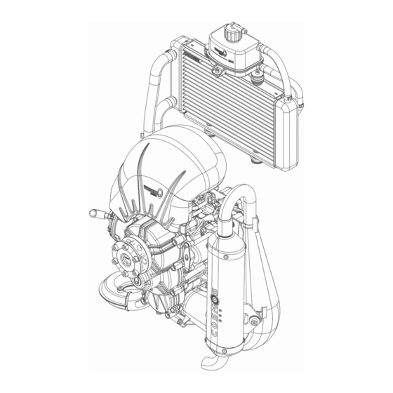
Page 37: Cooling System
The radiator must be positioned within the parameters indicated in the next drawings. In the case of different installations or outside the required parameters due to the geometry of the aircraft, contact Vittorazi directly. Straight radiator configuration Cosmos 300 - Installation manual - V3... - Page 38 Cosmos 300 - Installation manual - V3...
- Page 39 Inclined radiator configuration Cosmos 300 - Installation manual - V3...
- Page 40 Cosmos 300 - Installation manual - V3...
- Page 41 Two brackets are required to fix the radiator to the frame: • Upper bracket (between the radiator and the coolant reservoir). • Lower bracket. These brackets can be manufactured and integrated into the frame in accordance with the drawings provided. Cosmos 300 - Installation manual - V3...
- Page 42 Place 2 washers 10x28x2,5 (2) between the vibration dampers (5) and the radiator. • Place 2 washers 5x28x2,5 (1) under the vibration dampers (5). • Insert 2 Allen screws M5x16 (3) and tighten. Cosmos 300 - Installation manual - V3...
- Page 43 Place the coolant reservoir with the cap and the 2 hoses on top of the bracket. • Fix the coolant reservoir with 3 Allen screws M5x16 and 3 nuts, connect the pipes to the radiator. Cosmos 300 - Installation manual - V3...
- Page 44 Tighten the supplied pipe clamps with suitable pliers and ensure that the connection is secure. • Fix both brackets to the frame using the 3 holes provided. Cosmos 300 - Installation manual - V3...
- Page 45 3 cms to the required length at the end of the hose (highlighted in yellow in the figure). This is necessary to prevent the hose from being damaged by vibrations and movements of the engine when it is running and accelerating. Cosmos 300 - Installation manual - V3...
- Page 46 • Temporarily connect the lower (2) hose from the radiator to the water pump. • Cut the hose and tighten the clamp with suitable pliers and ensure that the connection is secure. Cosmos 300 - Installation manual - V3...
- Page 47 • The clip (3) is to be positioned between the 2 hoses. Once the cooling system has been installed, the coolant supplied must be added: • Remove upper cap from the coolant reservoir. Cosmos 300 - Installation manual - V3...
- Page 48 -20 °C and 110 °C) into the coolant reservoir up to the maximum level. • Remove vent screw with copper seal from the cylinder to allow any air to escape. • Replace copper seal. Cosmos 300 - Installation manual - V3...
- Page 49 • When a few drops of coolant escape, close with vent screw and copper seal. • Fill the coolant reservoir again with coolant up to the maximum level. Cosmos 300 - Installation manual - V3...
- Page 50 If the coolant level has dropped add more coolant up to the maximum level. • Screw upper cap on the coolant reservoir. • Apply a tube from the tank cap to the bottom of the frame to allow any excess liquid or vapor to vent safely. Cosmos 300 - Installation manual - V3...
- Page 51 65 °C If the outside temperature is below 15 °C, cover the central part of the radiator (1) with the radiator band (2). The radiator band is an available option designed by Vittorazi. Cosmos 300 - Installation manual - V3...
-
Page 52: Bowden Carburettor Cables
Choke system. Screw the accelerator Bowden cable inside the elbow (2) and fix the sheath to the clamp (1) shown in the figure. Screw the Choke Bowden cable into the elbow (3). Cosmos 300 - Installation manual - V3... - Page 53 All of these controls should be performed without the airbox to visually check operations. The checks will be repeated again even with the airbox installed. Cosmos 300 - Installation manual - V3...
-
Page 54: Manual Starter
Depending on the installation's choice, the manual starter can be rotated in 3 different positions (every 120 degrees) to allow for a different position of the handle, through a nautical-type pulley, fixed to the frame in which the rope runs. Cosmos 300 - Installation manual - V3... - Page 55 The position of the pulley fixed to the frame allows the rope to come out centred from the bush, to avoid strong friction and premature wear. Cosmos 300 - Installation manual - V3...
- Page 56 According to the final position, secure the handle with a knot and trim the excess rope at the end. Cosmos 300 - Installation manual - V3...
-
Page 57: Transmission Oil Filling
This operation is only possible with the airbox not installed on the engine. Place the engine in a vertical position before filling the transmission with oil. To properly fill the transmission: • Remove upper cap with copper seal. Cosmos 300 - Installation manual - V3... - Page 58 Insert all the oil of the bottle (250 mls). The oil contained is Motul Transoil 10W-40. • Wait a few minutes for the oil to settle. • Check the oil level: if oil is leaking from the front hole, wait until no more oil comes out. Cosmos 300 - Installation manual - V3...
- Page 59 • Replace copper seal. • Insert front screw with copper seal. • Insert upper cap with copper seal. Cosmos 300 - Installation manual - V3...
-
Page 60: Airbox
3.9 Airbox To install the airbox on the engine: • Connect the airbox sleeve to the carburettor inlet flange and 2 Snaplocks to the pins fixed on the engine. Cosmos 300 - Installation manual - V3... - Page 61 The airbox sleeve (1) must be completely inserted into the airbox connector (2), the fixing clamp (3) correctly inserted on the seat and aligned as in the figure. • Tighten the fixing clamp by applying 2,5 Nm torque to the screw. Cosmos 300 - Installation manual - V3...
- Page 62 Attach the safety strap to the support bracket behind the airbox, ensuring that the strap is tightened firmly. After installation, check that there is no relative movement between the rubber sleeve and the airbox connector. Cosmos 300 - Installation manual - V3...
-
Page 63: Propeller
3.10 Propeller Refer chapter 4.1 “Propeller assembling” in the User manual. Cosmos 300 - Installation manual - V3... -
Page 64: Instruments And Accessories
The engine is water-cooled and the temperature sensor is supplied but not installed. Remove cap and copper seal from the engine head. Cosmos 300 - Installation manual - V3... - Page 65 • Replace copper seal. Screw the temperature sensor (M10x1) with copper seal in the engine head and proceed with electrical connection. Cosmos 300 - Installation manual - V3...
- Page 66 Temperature sensor. Cosmos 300 - Installation manual - V3...
- Page 67 Screw the EGT sensor (M8x1) with copper seal in the exhaust pipe hole and proceed with the electrical connection. Refer to chapter 2 for engine limits to be respected (RPM, water temperature, EGT). Cosmos 300 - Installation manual - V3...
-
Page 68: Final Checks
For each new model aircraft, a series of test must be performed and documented in appropriate reports after the initial engine installation. The company Vittorazi strongly recommends sending those reports that contain operating data (RPM, temperatures, consumption, etc) for validation. Cosmos 300 - Installation manual - V3... - Page 69 Cosmos 300 - Installation manual - V3...
- Page 70 Cosmos 300 - Installation manual - V3...
Need help?
Do you have a question about the COSMOS 300 and is the answer not in the manual?
Questions and answers