Table of Contents
Advertisement
Available languages
Available languages
Quick Links
Manuel de l'Utilisateur
212VLL
Operator's Manual
Perceuse à colonne
Drill Press
ATTENTION:
Lisez et respectez toutes les règles de sécurité et les
instructions d'utilisation avant d'utiliser ce produit pour la première fois.
Ce manuel est à conserver avec l'équipement.
CAUTION:
Read and follow all Safety Rules and Operating Instructions
before First Use of this Product. Keep this manual with tools.
Advertisement
Table of Contents

Related Manuals for Promac 212VLL


Summary of Contents for Promac 212VLL
- Page 1 Manuel de l’Utilisateur 212VLL Operator’s Manual Perceuse à colonne Drill Press ATTENTION: Lisez et respectez toutes les règles de sécurité et les instructions d'utilisation avant d’utiliser ce produit pour la première fois. Ce manuel est à conserver avec l’équipement. CAUTION: Read and follow all Safety Rules and Operating Instructions before First Use of this Product.
- Page 2 Décla on de Conformité CE Product / Produkt / Produit: Drill Press Säulenbohrmaschine Perceuse d'établi 212VLL Brand / Marke / Marque: PROMAC Manufacturer / Hersteller / Fabricant: TOOL FRANCE SAS 9 Rue des Pyrénées, 91090 LISSES, France We hereby declare that this product complies with the regula Wir erklären hiermit, dass dieses Produkt der folgenden Richtlinie entspricht...
-
Page 3: Signification Des Symboles
FR- Français SYMBOLES DE SECURITE Certains des symboles ci-dessous peuvent concerner votre outil. Veuillez les étudier et apprendre leur signification. Une interprétation correcte de ces symboles vous permettra d'utiliser l'outil de manière plus efficace et plus sûre. Symbole Désignation / Explication Volt Tension Ampère... - Page 4 même ou d'autres personnes. Respectez toujours les consignes de sécurité afin de réduire les risques d'incendie, d'électrocution et de blessures corporelles. Le non-respect de cet avertissement de sécurité PEUT entraîner la mort ou de graves blessures pour vous-même ou d'autres personnes. Respectez toujours les consignes de sécurité afin de réduire les risques d'incendie, d'électrocution et de blessures corporelles.
- Page 5 LA POUSSIERE GENEREE PAR VOTRE PERCEUSE TANT QU’ELLE N’EST PAS CERTAINES MATIERES PEUT ÊTRE DANGEREUSE COMPLETEMENT MONTEE INSTALLEE POUR SANTE. UTILISEZ TOUJOURS CONFORMEMENT AUX INSTRUCTIONS. PERCEUSE A COLONNE DANS UN ENDROIT BIEN VENTILÉ. UTILISEZ AUTANT QUE POSSIBLE DES NE METTEZ JAMAIS EN MARCHE LA PERCEUSE SYSTEMES DE DEPOUSSIERAGE/RECUPERATION tant que l’établi/la table n'est pas débarrassé(e) de tout DES POUSSIERES.
- Page 6 INSTRUCTIONS DE MISE A LA TERRE l'opérateur contre les chocs électriques. Cette machine est uniquement destinée à être utilisée en intérieur. Ne pas l'exposer à la Cet outil doit être raccordé à la terre pluie et ne pas l'utiliser en milieu humide. lorsqu'il est utilisé...
-
Page 7: Vue D'ensemble
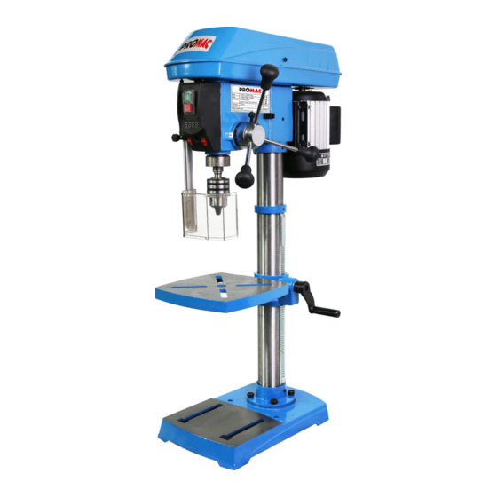
VUE D’ENSEMBLE FIG.1 Interrupteur ON Manivelle Interrupteur OFF M Support de colonne C Afficheur numérique de vitesse N Socle D Mandrin O Boulon de verrouillage table Ecran de protection Graduation d’inclinaison table Table Q Interrupteur laser à lignes ON/OFF G Poignées d’avance, robustes R Interr. -
Page 8: Specifications
SPECIFICATIONS PERCEUSE D’ETABL AVEC LASER A LIGNES REF. MODELE : 212VLL MOTEUR : 230V 50Hz PUISSANCE : 550W VITESSE : 450-2500RPM COL DE CYGNE : 155 mm CÔNE DE BROCHE : CAPACITE MANDRIN : 3-16 mm FOURREAU : 65 mm ∅... -
Page 9: Montage
Ensemble tête/moteur Poignées d’avance et de vitesse (4) Ensemble colonne et support de table Ampoule LED Table Clé de réglage de la table Socle Chasse-cône Mandrin Tige support d’écran Clé de mandrin Ecran de protection Poignée de verrouillage de la table Joint pour vis Boulons à... - Page 10 Tête de la perceuse sur colonne (Fig. 5) Poignée de commande de la vitesse (Fig. 7) La tête de la perceuse à colonne 1. Insérez la poignée (1) dans l’orifice fileté du moyeu de lourde. Pour éviter toute blessure, deux vitesses (2).
- Page 11 DEBRANCHEZ LA PERCEUSE Démontage du mandrin (Fig. 11) SOURCE D'ALIMENTATION AVANT 1. Tournez les poignées d’avance pour descendre le INSTALLATION, REGLAGE OU AVANT DE RETIRER mandrin (1) en position basse. LE MANDRIN. 2. Placer une clé (3; non fournie) au-dessus du mandrin et taper légèrement sur la clé...
- Page 12 1. Desserrez la poignée de verrouillage du support (1) et Montage des forets (Fig. 15) tournez la table autour de la colonne jusqu'à la position 1. Placez la clé du mandrin (1) dans le trou latéral du souhaitée. mandrin (2), en faisant s'engrener la clé avec les dents de Remarque : La crémaillère doit pouvoir tourner autour de l'engrenage.
- Page 13 certains réajustements. où le foret est en contact avec la pièce. 4. Si le laser doit être réglé : a. A l'aide d'une clé hexagonale de 3 mm, tournez les vis FIG.17 de réglage du laser (3) dans le sens antihoraire. b.
- Page 14 FIG.20 1. Retirez la vis qui maintient le couvercle du boîtier (1). Ouvrez le couvercle du boîtier. 2. Retirez la courroie (2) du couvercle du boîtier si elle est rompue. Si elle n’est pas rompue mais trop détendue pour fonctionner correctement, retirez la courroie de la broche d'entraînement (moteur) (3).
- Page 15 FONCTIONNEMENT FIG.22 incontrôlée, il doit être en contact avec le côté gauche (3) de la colonne, comme illustré, ou être fixé (4 ; fourniture non inclue) sur la table. Remarque : Pour des pièces de petites dimensions ne pouvant pas être serrées sur la table, utilisez un étau pour perceuse à...
-
Page 16: Maintenance
technique à droite concernant les vitesses recommandées (1). Utilisez le tableau qui suit pour déterminer la vitesse selon la matière de la pièce. recommandée selon la taille de foret utilisée et le type de matière à percer. Pendant le perçage, vérifiez la vitesse FIG.24 sur l’afficheur numérique (2) situé... -
Page 17: Resolution Des Problemes
RESOLUTION DES PROBLEMES PROBLEME CAUSE PROBABLE ACTION CORRECTIVE • Régler la tension de la courroie. Voir « Remplacement de 1. Tension incorrecte de la la courroie » dans le § REGLAGES. courroie. • Lubrifier la broche. Voir le § MAINTENANCE. Fonctionnement 2. - Page 18 RESOLUTION DES PROBLEMES PROBLEME CAUSE PROBABLE ACTION CORRECTIVE La pièce se • Toujours utiliser un matériau support. Voir « 1. Absence de matériau support fendille sur la Positionnement de la table et de la pièce » dans le § sous la pièce. face inférieure.
- Page 19 VUEE ECLATEE...
- Page 20 NOMENCLATURE 212VLL REP. DESCRIPTION QTE. REP. DESCRIPTION QTE. Vis ber, M4x8 Boulon hexagonal, M8x25 Socle Rondelle Blocage du support Moteur Vis à six pans creux, M8x8 Clavette, C4x76 Boulon hexagonal, M16x35 Boulon hexagonal, M8x12 Support de colonne Support moteur Boulon hexagonal, M10x30 Fixation du câble...
- Page 21 Ressort Microrupteur Protection du ressort Vis M5*10 Courroie Rondelle Disque d’entraînement moteur Vis M5*16 Disque d’entraînement arbre principal Microrupteur Circlip Marquage angulaire Roulement 6907Z Rondelle Cadran de contrôle de vitesse Vis cruciforme M6*12 Butée d’arbre 1 Boulon de fixation Butée d’arbre 2 Tige d’écran de protection Disque fixe moteur Ecran de protection...
-
Page 22: Safety Symbols
UK-English SAFETY SYMBOLS Some of the following symbols may be used on your tool. Please study them and learn their meaning. proper interpretation of these symbols will allow you to operate the tool better and safer. Symbol Name Designation / Explanation Volts Voltage Amperes... - Page 23 injury. Failure to obey this safety warning CAN result in death or serious injury to yourself or to others. Always follow the safety precautions to reduce the risk of fire, electric shock and personal injury. Failure to obey this safety warning MAY result in personal injury to yourself or others or property damage.
-
Page 24: Laser Safety
YOUR HEALTH. ALWAYS OPERATE THE DRILL INSTRUCTIONS. PRESS IN A WELL-VENTILATED AREA. USE DUST COLLECTION SYSTEMS WHENEVER POSSIBLE. NEVER TURN THE BENCH DRILL PRESS ON until the table is clear of all foreign objects (tools, scraps, etc.). ALWAYS WEAR EYE PROTECTION ALWAYS KEEP hands and fingers away from the drill bit. - Page 25 This tool must be grounded while in protect operator from electrical shock. use to protect the operator from electrical shock. This machine is for indoor use only. EVENT MALFUNCTION Do not expose to rain or use in damp locations. BREAKDOWN, grounding provides a path of least GUIDELINES FOR EXTENSION CORDS resistance for electric current and reduces the risk of electric shock.
- Page 26 OVERVIEW FIG.1 A power ON switch L Crank handle B power OFF switch M Column support C Digital speed readout N Base D Chuck O Table lock bolt E Safety goggles P Bevel scale F Table Q Laser line ON/OFF switch G Large, heavy-duty feed handles R LED work light switch H Housing cover screw...
-
Page 27: Assembly And Adjustments
SPECIFICATIONS BENCH DRILL PRESS WITH LASER LINE MODEL NO.: 212VLL MOTOR: 230V 50Hz POWER: 550W SPEED: 450-2500RPM SWING: 12” (305 mm) SPINDLE TAPER: CHUCK CAPACITY: 1/8-5/8” (3-16 mm) QUILL DIAMETER: 2 3/5” (65 mm) STROKE: 3 1/8” (80 mm) CAPACITY: 6”... - Page 28 Head/motor assembly Feed and speed handles (4) Column assembly and table bracket LED bulb Table Table adjustment wrench Base Wedge Chuck Goggle rod Chuck key Safety goggle Table lock handle Screw gasket Hex head bolts (4) Goggle rod shaft screw Table crank handle Fixing bolt of goggle rod Hex keys (2)
- Page 29 Drill press head to column (Fig. 5) Speed handle (Fig. 7) The drill press head is heavy. To Insert the feed handle (1) into the threaded opening avoid injury, two people should lift it into position. on the speed hub (2). Manually tighten handle into opening.
- Page 30 To remove the chuck (Fig. 11) DISCONNECT BENCH DRILL PRESS FROM THE POWER SOURCE BEFORE Turn the feed handles (1) to lower the chuck INSTALLING, ADJUSTING, OR REMOVING THE (2) to the lowest position. CHUCK. Place a ball joint separator (3; not included) above the chuck and tap the separator lightly with a hammer (4;...
- Page 31 To install drill bits (Fig. 15) Loosen the support lock handle (1) and turn the table Place the chuck key (1) into the side keyhole of the around the column to the desired position. Note: The rack should rotate around the column with the chuck (2), meshing the key with the gear teeth.
- Page 32 the drill press may make some readjustments necessary. laser lines should cross where the drill meets the workpiece. FIG.17 If the laser needs to be adjusted: Using a 3 mm hex key, turn the laser adjustment set screws (3) counter-clockwise. Rotate the laser light housing (4) until the two laser lines intersect where the drill meets the workpiece.
- Page 33 of the spindle and feed handles will become sluggish. Belt tension and bench drill press speed is controlled by automatic adjustments made to the diameter of the front FIG.20 spindle when the drive handle is moved. Note: See (Fig. 24) for information on the variable speed function of this bench drill press.
-
Page 34: Operation
OPERATION FIG.22 To keep the material from spinning out of control, it must contact the left side (3) of the column as illustrated, or be clamped (4; not included) to the table. Note: For small workpieces that cannot be clamped to the table, use a drill press vise (not included). - Page 35 Softer materials require greater speed than harder decrease the speed when operating, raise or lower the speed handle (1). materials. See right speadsheet for recommended speeds for the workpiece material. Use the following table to determine the recommended speed for the drill size you are using and the type of FIG.24 material you are to drill.
-
Page 36: Troubleshooting
TROUBLE SHOOTING PROBLEM PROBABLE CAUSE REMEDY • Adjust the belt tension. See "To replace the belt" in ADJUSTMENTS. • Lubricate the spindle. See MAINTENANCE 1. Incorrect belt tension. section. 2. Dry spindle. Noisy operation. 3. Loose spindle pulley. • Tighten the retaining nut on the pulley 4. - Page 37 TROUBLE SHOOTING PROBLEM PROBABLE CAUSE REMEDY The workpiece 1. No backup material under the • Always use a backup material. See "Position the splinters on the workpiece. table and workpiece" in OPERATION. underside. The workpiece is • Support workpiece using extension wing or 1.
-
Page 38: Assembly Diagram
ASSEMBLY DIAGRAM... - Page 39 212VLL PART LIST DESCRIPTION QNT'Y DESCRIPTION QNT'Y Pan Head Screw, M4x8 Hex bolt, M8x25 Base Washer Support clamp Motor Hex socket screw, M8x8 Key, C4x76 Hex bolt, M16x35 Hex bolt, M8x12 Support column Motor mount Hex bolt, M10x30 Wire fixator...
- Page 40 Spring Microswitch Spring guard Screw M5*10 Belt Washer Motor driving wheel Screw M5*16 Main shaft driving wheel Microswitch Hole stop Angle label Bearing 6907Z Washer Speed control dial Cross head screw M6*12 Shaft stop 1 Fixing bolt Shaft stop 2 Safety goggle rod Motor fixed wheel Safety goggle...
Need help?
Do you have a question about the 212VLL and is the answer not in the manual?
Questions and answers