Table of Contents
Advertisement
Quick Links
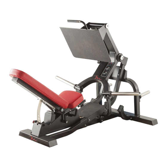
Model No. F304.0
Serial No.
Write the serial number in the
space above for reference.
QUESTIONS?
If you have questions, or if parts
are damaged or missing, please
see HOW TO CONTACT
CUSTOMER CARE on the back
cover of this manual.
CAUTION
Read all precautions and instruc-
tions in this manual before using
this equipment. Keep this manual
for future reference.
Serial
Number
Decal
OWNER’'S MANUAL
www.freemotionfitness.com
Advertisement
Table of Contents

Subscribe to Our Youtube Channel
Related Manuals for Freemotion F304.0


Summary of Contents for Freemotion F304.0
- Page 1 Model No. F304.0 Serial No. OWNER’’S MANUAL Write the serial number in the space above for reference. Serial Number Decal QUESTIONS? If you have questions, or if parts are damaged or missing, please see HOW TO CONTACT CUSTOMER CARE on the back cover of this manual.
-
Page 2: Table Of Contents
This drawing shows the location(s) of the warning decal(s). If a decal is missing or illegible, see the back cover of this manual and request a free replacement decal. Apply the decal in the location shown. Note: The decal(s) may not be shown at actual size. FREEMOTION is a registered trademark of ICON IP, Inc. -
Page 3: Important Precautions
To reduce the risk of serious injury, read all important precautions and instructions in this manual and all warnings on your strength equipment before using your strength equipment. FreeMotion Fitness assumes no responsibility for personal injury or property damage sustained by or through the use of this product. -
Page 4: Before You Begin
BEFORE YOU BEGIN Thank you for selecting the FREEMOTION of this manual. To help us assist you, note the product ® PRESS strength equipment. With unrestricted motion, model number and serial number before contacting us. you can work your body’’s muscle groups the way you The model number and the location of the serial num- do naturally, to train more effectively and efficiently. -
Page 5: Part Identification Chart
PART IDENTIFICATION CHART Use the drawings below to identify the small parts needed for assembly. The number in parentheses below each drawing is the key number of the part, from the PART LIST near the end of this manual. The number following the key number is the quantity needed for assembly. -
Page 6: Assembly
ASSEMBLY •• Assembly requires two persons. •• The following tools (not included) are required for assembly: •• Because of its weight and size, assemble the strength equipment in the location where it will be one adjustable wrench used. Make sure that there is enough clearance around the strength equipment. - Page 7 2. Orient the Base (1) as shown. Attach the Base (1) to the Front Frame (16) with four M12 x 95mm Bolts (59), eight M12 Washers (64), and four M12 Locknuts (66); do not tighten the Bolts yet. 3. Orient the Seat Frame (2) assembly as shown. Insert the Connection Frame (17) through the Base (1) and then set the Seat Frame on the Base.
- Page 8 4. Attach one of the Weight Storage Bars (15) to the Front Frame (16) with two M12 x 30mm Screws (60) and two M12 Washers (64). Attach the other Weight Storage Bar (15) to the Front Frame (16) in the same way. 5.
- Page 9 6. Attach a Weight Bar (21) to the Pivot Frame (11) with two M12 x 30mm Screws (60) and two M12 Washers (64). Attach the other Weight Bar (21) to the Pivot Frame (11) in the same way. 7. Orient the Pivot Frame (11) as shown. While a second person holds the Pivot Frame inside the bracket on the Base (1), insert a Pivot Axle (24) through the Base and the Pivot Frame.
- Page 10 8. Attach the Seat (14) to the Seat Frame (2) with four M8 x 30mm Screws (54) and four M8 Washers (62) (only three of each are shown). 9. Attach the Backrest (13) to the Backrest Frame (20) with two M8 x 70mm Screws (55) and two M8 Washers (62).
- Page 11 10. Orient the Foot Frame (9) as shown. While a second person holds the Foot Frame on the Pivot Frame (11), insert a Pivot Axle (24) through the Foot Frame and the Pivot Frame. Attach a Pivot Cover (28) to each end of the Pivot Axle (24) with an M10 x 25mm Screw (61) and an M10 Washer (63) at the same time.
-
Page 12: Adjustment
ADJUSTMENT This section explains how to adjust the strength equipment. Make sure that all parts are properly tightened each time the strength equipment is used. Replace any worn parts immediately. ADDING WEIGHTS Slide the same amount of weight (not included) onto the Weight Bars (21). - Page 13 ADJUSTING THE SPOTTER FRAME` To allow the Foot Frame (9) to descend, push it upward and rotate the Adjustment Handles (5) so that the Spotter Frame (19) pivots toward the Seat (14). When you are finished exercising, return the Spotter Frame (19) to its position under the Pivot Frame (11).
-
Page 14: Maintenance And Troubleshooting
Personnel must also record and report any accident. To maintain the strength equipment’’s warranty, use only FREEMOTION parts for repair or replacement. If there are any questions or concerns, see HOW TO CONTACT CUSTOMER CARE on the back cover of this manual. - Page 15 NOTES...
- Page 16 NOTES...
-
Page 17: Part List
PART LIST Model No. F304.0 R1112A Key No. Qty. Description Key No. Qty. Description Base Bearing Seat Frame Seat Frame Bushing T-linkage Spotter Bushing Link Arm Link Bushing Adjustment Handle Backrest Cap Pivot Link Spotter Cap Left Handle Adjustment Cap... -
Page 18: Exploded Drawing
EXPLODED DRAWING A Model No. F304.0 R1112A... - Page 19 EXPLODED DRAWING B Model No. F304.0 R1112A...
-
Page 20: How To Contact Customer Care
LIST and the EXPLODED DRAWING near the end of this manual). In the United States and Canada Call: 1-800-201-2109, Mon.––Fri. 8 a.m.––5 p.m. MT Write: FreeMotion Fitness 1500 South 1000 West Logan, UT 84321-9813 United States Outside the United States and Canada Call: 001-800-527-5417 or 001-435-786-3521 Mon.––Fri.
Need help?
Do you have a question about the F304.0 and is the answer not in the manual?
Questions and answers